Note: Descriptions are shown in the official language in which they were submitted.
BUSHINGS, SEALING DEVICES, TUBING, AND
METHODS OF INSTALLING TUBING
CROSS-REFERENCE TO RELATED APPLICATION
N/A
FIELD OF INVENTION
The present invention relates to gas, liquid, and slurry piping systems as
well
as protective conduit systems for cable carrying purposes, and more
particularly to
bushings, sealing devices, tubing, methods of installing tubing incorporating
fittings
capable of transferring and dissipating energy.
BACKGROUND OF THE INVENTION
Gas and liquid piping systems utilizing corrugated stainless steel tubing
("CSST") and fittings are known. Such piping systems can be designed for use
in
combination with elevated pressures of up to about 25 psi or more and provide
advantages over traditional rigid black iron piping systems in terms of ease
and speed
of installation, elimination of onsite measuring, and reduction in the need
for certain
fittings such as elbows, tees, and couplings. Undesirably, the thin metal
walls are
vulnerable to failure when exposed to physical or electrical forces, such as
lightning
or fault currents.
Often, electrical currents will occur inside a structure. These electrical
currents, which can vary in duration and magnitude, can be the result of power
fault
currents or induced currents resulting from lightning interactions with a
house or
structure. The term "fault current" is typically used to describe an overload
in an
electrical system, but is used broadly herein to include any electrical
current that is
not normal in a specific system. These currents can be the result of any
number of
situations or events such as a lightning event. Electrical currents from
lightning can
reach a structure directly or indirectly. Direct currents result from
lightning that
attaches to the actual structure or a system contained within the structure.
When
current from a nearby lightning stroke moves through the ground or other
conductors
into a structure, it is referred to as indirect current. While both direct and
indirect
CA 2850739 2018-05-16
CA 02850739 2014-04-01
WO 2013/052200
PCT/US2012/050103
currents may enter a structure through a particular system, voltage can be
induced in
other systems in the structure, especially those in close proximity to piping
systems.
This can often result in an electrical flashover or arc between the adjacent
systems. A
flashover occurs when a large voltage differential exists between two
electrical
conductors, causing the air to ionize, the material between the conductive
bodies to be
punctured by the high voltage, and formation of a spark.
It usually takes a very large voltage differential to create a flashover
through a
good dielectric material. When a flashover does occur, the flow of electrons
through
the ionized path causes energy dissipation through heating and a shockwave (i.
e. ,
sound). The extent of heat and shock is directly related to the duration and
magnitude
of the electrical energy in the flashover. Frequently, the voltage required to
breakdown a dielectric material is enough to drive a relatively large amount
of energy
across the associated spark often resulting in damage to both conductors and
any
material between them. The primary mode of failure is extreme heating and
melting
of these materials.
Metals are electrically conductive materials, making CSST a very good
pathway for electrical currents. This leads to the potential for a flashover
if the CSST
is installed in close proximity to another conductor within a structure and
either one
becomes energized. A flashover like this is often the result of a lightning
event but it
is foreseeable that other events may also be capable a producing a sufficient
voltage
differential between conductors. It is possible that a flash like this can
cause enough
heat generation to melt a hole in the CSST, allowing fuel gas to escape. This
scenario
is worsened by the dielectric jacket that often surrounds CSST. This jacket
typically
breaks down in a very small area, creating a pinhole as a result of the
flashover. This
phenomenon focuses the flash and concentrates the heating of the stainless
steel
inside. The result is a reduced capability of the CSST to resist puncture from
flashover compared to un-jacketed pipe.
Accordingly, it would be desirable to provide corrugated tubing and sealing
devices having an increased resistance to physical and electrical forces that
approaches that of conventional black iron pipe.
SUMMARY OF THE INVENTION
Bushings, sealing devices, tubing, and methods of installing tubing are
provided.
2
CA 02850739 2014-04-01
WO 2013/052200
PCT/US2012/050103
One aspect of the invention provides a bushing having one or more axially-
extending tongues.
This aspect of the invention can have a variety of embodiments. The bushing
can be a split bushing. The bushing can be a two-piece bushing. The bushing
can
include two halves coupled by a living hinge. The bushing can include at least
two
axially-extending tongues. The one or more axially-extending tongues can have
a
substantially semi-circular profile.
The one or more axially-extending tongues can be tapered toward an end of
the bushing.
The one or more axially-extending tongues can have a taper angle of between
about 1
and about 4 . The one or more axially-extending tongues can have a taper angle
of
between about 2 and about 3 .
The bushing can be fabricated from a conductive material. The conductive
material can be a metal. The metal can be selected from the group consisting
of:
aluminum, copper, gold, iron, silver, zinc, and an alloy thereof. The alloy
can be
selected from the group consisting of brass, bronze, steel, and stainless
steel.
The bushing can further include one or more substantially circumferential ribs
adapted to engage one or more corrugations of a tube. The one or more
substantially
circumferential ribs can be located on a substantially opposite end of the
bushing from
the one or more axially-extending tongues.
The tube can be corrugated. The tube can be corrugated stainless steel tubing.
The one or more axially-extending tongues can be adapted to form electrical
continuity with the tube. The tube can include one or more conductive jacket
layers
and the one or more axially-extending tongues can be adapted to form
electrical
continuity with at least one of the one or more conductive jacket layers.
Another aspect of the invention provides a sealing device for connecting a
length of tubing. The sealing device includes a body member defining a sleeve
portion and a bushing arranged to be received in the sleeve portion. The
bushing
includes one or more tongues adapted and configured to be received over at
least one
layer of the tubing.
This aspect of the invention can have a variety of embodiments. The sealing
device can further include a nut adapted and configured for threaded coupling
with
the body member. The bushing and the nut can be dimensioned such that as the
nut is
tightened, the one or more tongues are compressed against the tubing by the
nut.
3
CA 02850739 2014-04-01
WO 2013/052200
PCT/US2012/050103
The tubing can include a jacket. The bushing and the nut can be dimensioned
such that as the nut is tightened, one or more layers of the jacket are
compressed
between an interior surface of the nut and an exterior surface of the one or
more
tongues.
The bushing and the nut can be dimensioned such that as the nut is tightened,
the one or more tongues are compressed against one or more layers of the
jacket by
the nut.
The nut can have an external thread and the sleeve portion of the body
member can have a complimentary internal thread.
The nut can have a tapered inner surface.
The nut can include a torque-limiting feature. The torque-limiting feature can
be a shear point.
Another aspect of the invention provides a length of tubing including an inner
tubing layer and a fitting coupled to an end of the tubing. The fitting
includes a body
member defining a sleeve portion and a bushing extending partially over at
least the
inner tubing layer and received along with at least the inner tubing layer in
the sleeve
portion. The bushing includes one or more tongues adapted and configured to be
received over the inner tubing layer.
This aspect of the invention can have a variety of embodiments. The length of
tubing can further include a conductive layer surrounding the outside of the
inner
tubing layer. The one or more tongues can be in contact with the conductive
layer.
The one or more tongues can be positioned between the inner tubing layer and
the
conductive layer. The length of tubing can further include an outer tubing
layer
surrounding the outside of the conductive layer. The one or more tongues can
be
positioned between the conductive layer and the outer tubing layer.
The inner tubing layer can be metallic tubing. The inner tubing layer can be
thin-walled tubing. The inner tubing layer can be flexible tubing. The inner
tubing
layer can be corrugated tubing. The outer tubing layer can be a resin layer.
The conductive layer can include a metal. The metal can be selected from the
group consisting of: aluminum, copper, gold, iron, silver, zinc, and an alloy
thereof.
The alloy can be selected from the group consisting of brass, bronze, steel,
and
stainless steel. The metal can be a metal foil. The metal foil can completely
surround
the inner tubing layer. The metal foil can be an expanded metal foil. The
metal can
be one or more metal wires. The conductive layer can comprise a conductive
resin.
4
CA 02850739 2014-04-01
WO 2013/052200
PCT/US2012/050103
The length of tubing can further include an inner resin layer positioned
between the inner tubing layer and the conductive layer.
Another aspect of the invention provides a method of installing energy
dissipative tubing. The method includes: providing
a length of tubing including an
inner tubing layer, providing a sealing device including a body member
defining a
sleeve portion and a bushing including one or more tongues adapted and
configured to
be received over the inner tubing layer; placing the bushing over at least the
inner
tubing layer such that the one or more tongues are positioned over the inner
tubing
layer; and inserting the bushing and at least the inner tubing layer into the
sleeve
portion.
This aspect of the invention can have a variety of embodiments. The method
can include coupling the sealing device to a device selected from the group
consisting
of: a pipe, a manifold, a meter, a gas main, a tank, and an appliance. The
pipe can be
black iron pipe. The appliance can be selected from the group consisting of: a
stove,
an oven, a grill, a furnace, a clothes dryer, a fireplace, and a generator.
The length of tubing can include a conductive layer surrounding the outside of
the inner tubing layer. The one or more tongues can be positioned in contact
with the
conductive layer. The one or more tongues can be positioned between the inner
tubing layer and the conductive layer.
The length of tubing can include an outer tubing layer surrounding the outside
of the conductive layer. The one or more tongues can be positioned between the
conductive layer and the outer tubing layer.
The method can further include tightening a nut to advance the bushing. The
step of tightening a nut can includes tightening the nut until a torque-
limiting portion
of the nut shears.
BRIEF DESCRIPTION OF THE DRAWINGS
For a fuller understanding of the nature and desired objects of the present
invention, reference is made to the following detailed description taken in
conjunction
with the accompanying drawing figures wherein like reference characters denote
corresponding parts throughout the several views and wherein:
FIG. 1 depicts a multi-layer jacketed tube in accordance with the prior art.
FIG. 2 depicts an energy dissipative tube in accordance with the prior art.
5
CA 02850739 2014-04-01
WO 2013/052200
PCT/US2012/050103
FIGS. 3A-3F depict embodiments of a sealing device and tubing assembly in
accordance with preferred embodiments of the invention.
FIGS. 4A-4D depict a nut including a torque-limiting feature in accordance
with a preferred embodiment of the invention.
FIG. 5 depicts a method for installing tubing in accordance with a preferred
embodiment of the invention.
DEFINITIONS
The instant invention is most clearly understood with reference to the
following definitions:
As used herein, the singular form "a," "an," and "the" include plural
references unless the context clearly dictates otherwise.
Unless specifically stated or obvious from context, as used herein, the term
"about" is understood as within a range of normal tolerance in the art, for
example
within 2 standard deviations of the mean. "About" can be understood as
within 10%, 9%, 8%, 7%, 6%, 5%, 4%, 3%, 2%, 1%, 0.5%, 0.1%, 0.05%, or 0.01%
of the stated value. Unless otherwise clear from context, all numerical values
provided herein are modified by the term about.
As used herein, the term "alloy" refers to a homogenous mixture or metallic
solid solution composed of two or more elements. Examples of alloys include
austentitic nickel-chromium-based superalloys, brass, bronze, steel, low
carbon steel,
phosphor bronze, stainless steel, and the like.
As used in the specification and claims, the terms "comprises," "comprising,"
"containing." "having." and the like can have the meaning ascribed to them in
U.S.
patent law and can mean "includes." "including," and the like.
As used herein, the terms "corrugated stainless steel tubing" and "CSST" refer
to any type of tubing or piping, which may accommodate corrosive or aggressive
gases or liquids, and includes but is not limited to tubing or piping made
from:
thermoplastics, metal or metal alloy materials such as olefin-based plastics
(e.g.,
polyethylene (PE)), fluorocarbon polymers (e.g., polytetrafluoroethylene
(PTFE)).
carbon steel, copper, brass, aluminum, titanium, nickel, and alloys thereof.
Unless specifically stated or obvious from context, the term "or," as used
herein, is understood to be inclusive.
6
CA 02850739 2014-04-01
WO 2013/052200
PCT/US2012/050103
As used herein, the term "metal" refers to any chemical element that is a good
conductor of electricity and/or heat. Examples of metals include, but are not
limited
to, aluminum, cadmium, niobium (also known as "columbium"), copper, gold,
iron,
nickel, platinum, silver, tantalum, titanium, zinc, zirconium, and the like.
As used herein, the term "resin" refers to any synthetic or naturally
occurring
polymer.
Ranges provided herein are understood to be shorthand for all of the values
within the range. For example, a range of 1 to 50 is understood to include any
number, combination of numbers, or sub-range from the group consisting 1, 2,
3, 4, 5,
6, 7, 8, 9, 10, 11, 12, 13, 14, 15, 16, 17, 18, 19, 20, 21, 22, 23, 24, 25,
26, 27, 28, 29,
30, 31, 32, 33, 34, 35, 36, 37, 38, 39, 40, 41, 42, 43, 44, 45, 46, 47, 48,
49, or 50 (as
well as fractions thereof unless the context clearly dictates otherwise).
DETAILED DESCRIPTION OF THE INVENTION
Corrugated Tubing
Referring to FIG. 1, a length of corrugated tubing 102 according to the prior
art is provided. The corrugated tubing 102 may be composed of stainless steel
or any
other suitable material. The tubing 102 contains a number of corrugation peaks
104
and corrugation valleys 106. A jacket 108 (e.g., a multi-layer jacket) covers
the
outside of the tubing 102.
The jacket 108 can include a plurality of layers 110, 112. The layers 110, 112
generally form an annulus around the tubing 102, but may have a circular or
non-
circular cross-section.
Energy Dissipative Tubing
Referring now to FIG. 2, in order to better absorb energy from fault currents
and lightning strikes, energy dissipative jackets are provided that dissipate
electrical
and thermal energy throughout the respective jackets, thereby protecting the
tubing 202. The term "dissipate" encompasses distributing electrical energy to
an
appropriate grounding device such as a fitting.
Preferred embodiments of energy dissipative jackets preferably include one or
more conductive layers for distributing electricity and heat. The conductive
layers
can include, for example, conductive resins and/or metals as discussed herein.
One embodiment of energy dissipative tubing 200 is depicted in FIG. 2. The
energy dissipative tubing 200 includes a length of tubing 202. The tubing 202
can be
7
CA 02850739 2014-04-01
WO 2013/052200
PCT/US2012/050103
metal tubing, thin-walled metal tubing, corrugated tubing, corrugated
stainless steel
tubing, or the like.
Tubing 202 is surrounded by a first resin layer 204, a metal layer 206, and a
second resin layer 208. Resin layers 204, 208 can be formed from insulative
and/or
conductive resins.
Insulating resin layers can be formed from a variety of materials. In some
embodiments, an insulating elastic layer includes polytetrafluoroethylene
(PTFE).
Other suitable insulators include polyolefin compounds, thermoplastic
polymers,
thermoset polymers, polymer compounds, polyethylene, crosslinked polyethylene,
UV-resistant polyethylene, ethylene-propylene rubber, silicone rubber,
polyvinyl
chloride (PVC), ethylene tetrafluoroethylene (ETFE), and ethylene propylene
diene
monomer (EPDM) rubber.
Conductive resin layers can be formed by impregnating a resin with
conductive material such as metal particles (e.g., copper, aluminum, gold,
silver,
nickel, and the like), carbon black, carbon fibers, or other conductive
additives. In
some embodiments, the metal layer 206 and/or one or more of the resin
layers 204, 208 has a higher electrical conductivity than the tubing 202. In
some
embodiments, the volume resistivity of the conductive resin can be less than
about 106
ohm-cm (e.g.. 9 x 10⁶ ohm-cm) as tested in accordance with ASTM standard
D4496.
In some embodiments, each resin layer 204, 208 has a thickness of
about 0.015" to about 0.035".
Metal layer 206 can include one or more metals (e.g., ductile metals) and
alloys thereof. The metal(s) can be formed into foils, perforated foils,
tapes,
perforated tapes, cables, wires, strands, meshes, braids, and the like.
In some embodiments, the metal layer 206 is an expanded metal foil as further
described in U.S. Patent Application Publication No. 2011-0041944. A variety
of
expanded metal foils are available from the Dexmet Corporation of Wallingford,
Connecticut. An exemplary embodiment of energy dissipative tubing 200 with
expanded metal foil is depicted in FIGS. 2.
In some embodiments, the metal layer 206 completely surrounds the first resin
layer 24. In such embodiments, the metal may overlap and/or be welded or
soldered
in some regions. In other embodiments, the metal layer 206 substantially
surrounds
the first resin layer 204. In such embodiments, a small portion of the first
resin
layer 204 (e.g., less than about 1 , less than about 2 , less than about 3 ,
less than
8
CA 02850739 2014-04-01
WO 2013/052200
PCT/US2012/050103
about 40, less than about 5 , less than about 100, less than about 15 , less
than
about 20 , and the like) is not surrounded by the metal layer 26. In still
other
embodiments, the metal layer 206 can be wrapped spirally or helically around
the first
resin layer 204. In such an embodiment, the metal layer 26 can overlap or
substantially surround the first resin layer 204
In some embodiments, the metal layer 206 is a conventional, non-expanded
metal foil, such as aluminum or copper foil that can, in some embodiments,
completely envelop the inner resin layer 206.
Various thicknesses of the resin layers 204, 208 and the metal layer 206 can
be
selected to achieve desired resistance to lightning strikes and physical
damage while
maintaining desired levels of flexibility. In embodiments including an
expanded
metal foil, the mass per area can be adjusted to provide an appropriate amount
of
energy dissipation. The resin layers 24, 28 can be the same or different
thickness and
can include the same or different materials. Various colors or markings can be
added
to resin layers, for example, to clearly distinguish the resin layers 24, 28
from each
other and from the metal layer 206 and/or to make the tubing 200 more
conspicuous.
Sealing Devices
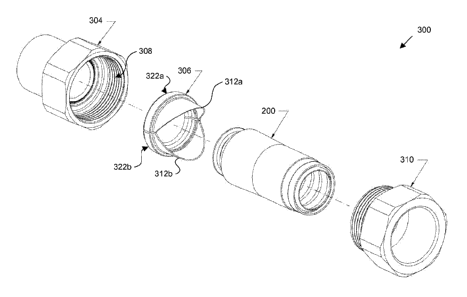
Referring now to FIG. 3A, an exploded view of a sealing device and tubing
assembly 300 is provided. The assembly 300 allows for the sealing and coupling
of
an end of tubing 200 to a pipe, a manifold, an appliance, and the like (not
depicted).
For example, after body member 304 is threaded onto a manifold (not depicted),
tubing 200 and bushing 306 can be placed inside the sleeve portion 308 of the
body
member 304 and sealed by advancing a nut 310 as further discussed below.
Although the assembly 300 can be used with a variety of types of CSST, the
.. bushing 306 is particularly advantageous when used with energy dissipative
tubing 200 having one or more conductive layers.
As further illustrated in FIGS. 3B-3D. bushing 306 includes one or more
axially-extending tongues 312a. 312b that can be placed in contact with the
corrugated tubing 202 and/or one or more of the jacket layers 204, 206. 208.
In the
embodiment depicted in FIGS. 3B-3D, the axially-extending tongues 312 are
placed
between metal layer 206 (e.g., a metal foil layer) and an outer resin layer
208.
However, other configurations are possible including placement of the tongues
312
between the tubing 202 and jacket layer 204, between jacket layer 204 and
jacket
layer 206, between jacket layer 206 and jacket layer 208, external to jacket
layer 208,
9
CA 02850739 2014-04-01
WO 2013/052200
PCT/US2012/050103
and the like. For example, when used in conjunction with single-jacketed
tubing, the
tongues 312 can be placed between the jacket layer 204 and the tubing 202 or
external
to the jacket 204 as depicted in FIG. 3E. Likewise, when used in conjunction
with
unjacketed tubing, the tongues 312 can be placed external to the tubing 202 as
depicted in FIG. 3F.
By placing the tongues 312 in contact with one or more conductive jacket
layers (e.g., metal foil layer 206) and/or the tubing 202, the tongues 312 can
form
electrical continuity with one or more the conductive elements of the tubing
200,
thereby effectively grounding electrical charges applied to the tubing 200
while
.. minimizing the risk of damage-causing flashover at the sealing device
As most clearly seen in FIGS. 3C and 3D, axially-extending tongues 312 can,
in some embodiments, be tapered to facilitate placement of the tongues under
one or
more jacket layers 204, 206, 208. For example, the taper angle between an
inner wall
and the outer wall of the tongues 312 can be between about 0 and about 5 ,
between
about 0 and about 1 , between about 1 and about 2 , between about 2 and
about 3 ,
between about 3 and about 4 , between about 4 and about 5 , between about 1
and
about 4 , between about 2 and about 3 , and the like.
The axially-extending tongues 312 can, in some embodiments, also have a
tapered profile when viewed from perpendicular to the longitudinal axis of the
tubing 200. A tongue 312 that substantially culminates in a point can enable
easier
insertion of the tongue 312 between multiple layers of the tubing 200. For
example,
the tongues 312 can have a substantially semi-circular or triangular profile
when
viewed from perpendicular to the longitudinal axis of the tubing 200 (depicted
in
dashed lines in FIGS. 3A-3C).
Bushing 306 can, in some embodiments, be a split bushing. For example,
bushing 306 can include two halves 322a, 322b (each having a tongue 312a,
312b)
connected by a living hinge. A living hinge allows the bushing to open to
allow
ribs 326a, 326b to slide over one or more corrugation peaks 104 before resting
in a
corrugation groove 106 and allowing the bushing 306 to return to a
substantially
circular profile for engagement with body member 304. In other embodiments,
the
bushing 306 is a two-piece split bushing such that each half of the split
bushing is
individually positioned on the tubing prior to insertion into the sleeve
portion 308 of
the body member 304.
CA 02850739 2014-04-01
WO 2013/052200
PCT/US2012/050103
In one embodiment, ribs 326 engage the first corrugation groove 106 of the
tubing to facilitate the sealing of the tubing 200 against the body member
304. The
ribs 326 can be located on a substantially opposite end of the bushing 306
from the
tongues 312. As the nut 310 is advanced, the ribs 326 of the bushing 306 press
the
tubing 200 against the sealing face of the body member 304, causing the first
corrugation peak 104 to collapse and form a gastight seal.
As most clearly visible in FIG. 3D, body member 304 can include a sealing
face having one or more sealing circular ridges 328a, 328b configured to
facilitate a
metal-to-metal gastight seal. Such a sealing architecture is further described
in U.S.
Patent Nos. 7,607,700 and 7,621,567 and embodied in the XR2 fitting available
from
Gastite of Portland, Tennessee.
Additionally, the axially-extending tongues 312 described herein can be
adopted to a variety of other fitting architectures including, but not limited
to, the
architectures described in U.S. Patent Application Publication Nos. 2010-
0181760
and 2010-0201124, as well as other CSST fittings produced by other
manufacturers.
Referring still to FIGS. 3A-3D, nut 310 can have external threads 330
configured to mate with internal threads 332 in the sleeve portion 308 of body
member 304. As the nut 310 is rotated, the threads 330, 332 cause the nut 310
to
advance towards the body member 304. The nut 310 engages with the tubing 200,
the
bushing 306, and/or the tongues 312 to drive the tubing 200 forward to crush a
corrugation peak 104 to form the seal depicted in FIGS. 3C and 3D.
Nut 310 can have an internal taper complimentary to the external taper of
tongues 312. This complimentary taper can advantageously press the tongues 312
against a conductive layer, press a conductive layer against the tongues,
and/or
compress one or more layers of the jacket between the tongues 312 and nut 310
to
retain the jacket within the sealing device.
In some embodiments, one or more components of the sealing device are
fabricated from a conductive material such metals or metal alloys. For
example, the
bushing 306 and the body member 304 can be conductive to facilitate the
efficient
flow of electricity from the tubing 200 to the bushing 306 to the body member
304
and eventually to ground via whatever device is connected to the body member
304.
As will be appreciated by one of ordinary skill in the art, the various
components of
the sealing device can be fabricated by various techniques including casting,
stamping, machining, molding, and the like.
11
CA 02850739 2014-04-01
WO 2013/052200
PCT/US2012/050103
Torque-Limiting Nut
Referring now to FIG. 4, another embodiment of the invention utilizes a
nut 400 having a torque-limiting feature. The torque-limiting feature reduces
the
likelihood of an installer over-tightening or under-tightening a fitting by
providing
positive feedback to the installer when an appropriate amount of torque is
applied to
the nut 400.
One embodiment of such a nut 400 includes two hexagonal regions 402
and 404 separated by a notched shear point 406 having a reduced diameter (DO.
In
some embodiments, the distal hexagonal region 404 has a longer length (Ld)
than the
length (Lp) of the proximal hexagonal region 402 to promote the application of
torque
solely to the distal hexagonal region 404 during installation.
During installation, a wrench, pliers, or other tool is applied to the distal
hexagonal region 404 to advance the nut 400 to form a seal as described
herein. Once
the seal is formed and predetermined amount of torque (e.g., about 50 foot-
pounds) is
applied to the distal hexagonal region 404, the distal hexagonal portion 404
shears
from the remainder of the nut 400 at the shear point 406. In some embodiments,
the
proximal hexagonal portion 404 remains to allow removal of the nut. In other
embodiments, a shear point is positioned between the threaded portion of the
nut and
the hexagonal portion to preclude removal of the nut 400 for safety purposes.
The amount of permissible torque can be determined by one of ordinary skill
in the art by design and/or testing and may vary to reflect various designs,
materials,
and dimensions of the tubing 200 and sealing device. In general, a deeper
notch at
shear point 406 will result in the application of less torque before shearing.
Although the nuts 310, 400 are depicted and described herein as hexagonal,
one of ordinary skill in the art will readily appreciate that other geometries
can be
utilized including square, octagonal, and the like.
Methods of Installing Tubing
Tubing can be installed in accordance with existing techniques for the
manufacture of CSST. An exemplary method 500 for installing energy dissipative
tubing is depicted in FIG. 5.
In step S502, a length of tubing is provided. Tubing can, in some
embodiments, be CSST such as unjacketed CSST, jacketed CSST, and energy-
dissipative tubing. Tubing may be provided in lengths (e.g., 8' sticks) or on
reels.
12
In step S504, one or more jacket layers are optionally removed in accordance
with the instructions for a fitting. The one or more layers can be removed
with
existing tools such as a utility knife, a razor blade, a tubing cutter, and
the like.
In step S506, a sealing device is provided including a body member defining a
sleeve portion and a bushing including one or more tongues adapted and
configured to
be received over at least an inner tubing layer of the length of tubing.
In step S508, the sealing device is optionally coupled to another device. For
example, the sealing device can be coupled to a source of a fuel gas such as a
pipe, a
manifold, a meter, a gas main, a tank, and the like. In another example, the
sealing
device can be coupled to an appliance that consumes a fuel gas such as a
stove, an
oven, a grill, a furnace, a clothes dryer, a fire place, a generator, and the
like. The
sealing device can be coupled to the other device by threaded or other
attachments. In
some circumstances, pipe seal tape (e.g., polytetrafluoroethylene tape) or
pipe seal
compound (commonly referred to as "pipe dope") is utilized to facilitate a
gastight
.. seal between the sealing device and the other device.
In step S510, the bushing is placed over the inner tubing layer. The bushing
can be positioned such that one or more tongues are located between one or
more
layers of the tubing. For example, the bushing can be positioned such that the
one or
more tongues are located in contact with a conductive layer of the tubing.
In step S512, a nut is advanced to form a seal. The nut can be advanced by
rotating the nut to engage threads in the sleeve portion of the body member.
In step S514, the nut is optionally tightened until a torque-limiting portion
of
the nut is activated. For example, a portion of the nut may shear off when a
predetermined amount of torque is applied to the nut.
30
13
CA 2850739 2018-05-16