Note: Descriptions are shown in the official language in which they were submitted.
CA 02850835 2014-05-01
Title
SOLAR POWERED DISPENSER SYSTEM
Scope of the Invention
100011 This invention relates to solar powered apparatus and, more
particularly, to a system
for controlling a solar powered dispenser by control of an electrically
powered light source.
Background of the Invention
100021 Dispensers of hand cleaning fluid are known to be placed at
locations for easy
access by persons as, for example, at locations within a building where
persons will pass. For
example, in many hospitals, it is desired to provide dispensers of hand
cleaners in lobbies and
proximate entrances and exits. Hand cleaning dispensers are known which are
touchless to
minimize cross contamination between persons using the dispensers. Such
touchless dispensers
typically require electrical energy to sense the presence of a person and to
dispense fluid.
100031 Many dispensers which are placed in hospital lobbies and near
exitways and
passages suffer the disadvantage that they need to be powered by batteries
since hardwired
electrical supply is not convenient particularly in locations as in the middle
of a lobby.
100041 The present inventor has appreciated a disadvantage that battery
operated dispensers
frequently become inoperative due to the batteries not being changed timely.
Moreover,
disadvantages of battery operated dispensers include the substantial costs of
batteries due to the
labor required to replace batteries but also due to the disadvantage that some
fluid dispensers
may be used more frequently than others resulting in the need for some
dispensers to have their
batteries replaced frequently and others not so frequently.
Summary of the Invention
100051 To at least partially overcome these disadvantages of previously
known devices, the
present invention provides a system and method for dispensing hand cleaning
fluid material
including a dispenser with a rechargeable battery powered by a solar
generator, a remote
electrically powered light source spaced from the dispenser directing light
onto the solar panel
of the dispenser and a control mechanism controlling the operation of the
light source in
CA 02850835 2014-05-01
relation to the status and operation of the dispenser. Preferably, the light
source is controlled
by communication wirelessly between the dispenser and the light source.
Preferably, the
dispenser is mounted on a floor or a wall and the light source is mounted to a
ceiling or a wall
above the dispenser.
100061 In one aspect, the present invention provides a preferred system and
method for
controlled driving of a solar element of a battery operated dispenser with a
hardwired light
source spaced from the solar element.
100071 In another aspect, the present invention provides a tower structure
for advantageous
solar powering of at least one or more dispensers removably mounted to the
tower.
[0008] In another aspect, the present invention provides a novel
configuration for a solar
powered dispenser in which a solar panel is disposed beneath a drip tray.
100091 In another aspect, the present invention provides a system for
controlling electrical
power from a solar element to an electrically powered fluid dispenser by the
control of a light
source spaced remote from the solar element, wherein:
100101 the light source includes:
100111 a light emitter of light;
100121 a light controller; and
100131 a wireless light communicator;
100141 the light source electrically coupled to an electrical power source;
100151 the light controller controlling the operation of the light emitter
by control of the
delivery of electrical power to the light emitter;
100161 the solar element and the dispenser are coupled together proximate
each other and
spaced from the light emitter;
100171 the dispenser comprising:
100181 a reservoir for a fluid to be dispensed,
100191 a pump to dispense the fluid from the dispenser;
100201 a dispenser controller controlling operation of the pump, and
100211 a wireless dispenser communicator;
2
CA 02850835 2014-05-01
100221 the solar element and the light emitter relatively juxtapositioned
spaced from each
other with the light emitted by the emitter directed toward and received by
the solar element,
[00231 the solar element generates electrical power from the light emitted
by the light
emitter received by the solar clement and provides the electrical power to the
dispenser,
[00241 the dispenser controller and the light controller together
controlling operation of the
light emitter in relation to the status or the operation of the dispenser by
wireless
communication between the dispenser controller and the light controller via
the wireless
dispenser communicator and the wireless light communicator.
100251 In a further aspect, the present invention provides a method for
controlling electrical
power from a solar element to an electrically powered fluid dispenser by the
control of a light
source spaced remote from the solar element,
100261 the method comprising:
100271 providing the light source including a light emitter of light, a
light controller, and a
wireless light communicator;
100281 providing an electrical power source electrically coupled to the
light source;
100291 controlling the operation of the light emitter by control of the
delivery of electrical
power to the light emitter with the light controller;
100301 providing the solar element and the dispenser coupled together
proximate each other
and spaced from the light emitter;
100311 the dispenser comprising:
100321 a reservoir for a fluid to be dispensed,
100331 a pump to dispense the fluid from the dispenser;
10034j a dispenser controller controlling operation of the pump, and
100351 a wireless dispenser communicator;
100361 providing the solar element and the light emitter relatively
juxtapositioned spaced
from each other with the light emitted by the emitter directed toward and
received by the solar
element,
100371 generating electrical power with the solar element from the light
emitted by the light
emitter received by the solar element and providing the electrical power to
the dispenser,
3
CA 02850835 2014-05-01
100381 controlling with the dispenser controller and the light controller
the operation of the
light emitter in relation to the status or the operation of the dispenser by
wireless
communication between the dispenser controller and the light controller via
the wireless
dispenser communicator and the wireless light communicator.
100391 In another aspect, the present invention provides a solar powered
fluid dispenser
comprising:
100401 a reservoir for a fluid to be dispensed,
100411 a pump to dispense the fluid from the dispenser downwardly out of a
discharge
outlet;
100421 a drip tray located below the outlet,
100431 a vertically extending hand space provided between the outlet and
the drip tray
above the drip tray within which a person's hands may be placed to receive
fluid dispensed
downwardly from the outlet,
100441 the drip tray having an upwardly directed tray catch surface to
catch fluid falling
downwardly from the outlet or from the person's hand located in the hand
space,
100451 the tray catch surface permitting light incident thereon to pass
through the tray catch
surface,
100461 a solar element located below the tray catch surface to receive the
light passing
through the tray catch surface and generate electrical power.
Brief Description of the Drawings
100471 Further aspects and advantages of the present invention will become
apparent from
the following description taken together with the accompanying drawings in
which:
100481 Figure 1 is a schematic pictorial view of a dispensing system in
accordance with a
first aspect of the present invention;
100491 Figure 2 is an enlarged pictorial view of a solar powered dispenser
on a tower stand
as shown in Figure 1;
100501 Figure 3 is a schematic representation of the dispensing system of
Figure 1 with the
solar powered dispenser shown schematically in side view;
4
=
[0051] Figure 4 is a pictorial view of a dispenser tower stand in
accordance with a second
embodiment of the present invention;
[0052] Figure 5 is a schematic partial cross-sectional view through the
stand of Figure 4;
[0053] Figure 6 is a schematic pictorial view of a solar dispenser stand
in accordance with a
third embodiment of the present invention; and
[0054] Figure 7 is a schematic partial cross-sectional view through the
stand of Figure 6.
Detailed Description of the Drawings
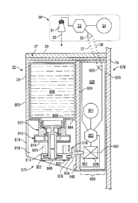
[0055] Reference is made to Figure 1 which illustrates a dispensing system
10 in
accordance with the first embodiment of the present invention. Figure 1
schematically
illustrates a portion of a building 12 partially cut away to show a pair of
walls 13 spanning
between a floor 14 and a ceiling 15. An access door 16 is shown through one of
the walls 13.
A dispenser assembly 20 is shown to be a free-standing stand or tower assembly
24 supported
on the floor 14. The dispenser assembly 20 includes a dispenser 22 of hand
cleaning fluid
mounted to the tower assembly 24 including a tower 25 and a floor engaging
base 26. The
tower 25 extends upwardly from the base 26 and is supported by the base 26.
The dispenser
assembly 20 preferably is free-standing and may be moved to different
locations on the floor 14
as may be desired to locate the dispenser 22 at desired locations for use
about the building. The
dispensing system 10 includes two separate lamps or light sources 30 shown,
one of which is
mounted to the ceiling 15 and another of which is mounted to one of the walls
13, however,
only one of the light sources 30 are necessary. The dispenser 22 carries on an
upwardly
directed surface thereof a solar element or solar panel 27. Each light source
30 includes a light
emitter 31 which directs light 32 outwardly therefrom such that at least a
portion of the light 32
falls on and is incident on the solar panel 27 whereby the solar panel 27
generates electricity to
power the dispenser 22.
[0056] Reference is made to Figure 3 which shows a schematic control
diagram for the
dispenser assembly 20 having one light source 30 and the dispenser 22. Figure
3 also shows a
schematic cross-sectional side view of the dispenser 22. The dispenser 22,
shown in Figure 3,
has many similarities to the dispenser shown in Figure 26 of U.S. Patent
Publication US
2013/0119093, published May 16, 2013 to Ophardt et al. Other dispensers can be
used. The
CA 2850835 2020-09-21
dispenser 22 includes a fluid containing reservoir 860 and a pump assembly
810. The pump
assembly 810 is secured in a neck 858 of the reservoir. The pump assembly 810
includes a
piston-forming element or piston 814 which is axially reciprocally slidable
within a piston
chamber-forming body or body 812 so as in a known manner to draw fluid such as
liquid soap
868 from the reservoir 860 and dispense the liquid mixed with air out an
outlet 848 at the lower
outer end of the piston 814. The pump assembly 810 shown has a configuration
similar to that
disclosed in U.S. Patent Publication US 2009/0145296 to Ophardt eta!,
published June 11,
2009. The pump assembly 810 illustrated is adapted for simultaneous discharge
of the liquid
from the reservoir together with air to provide a foam. Other piston pumps may
be utilized as,
for example, merely to dispense liquid. Other pump assemblies can be used
without any
limitation to the pump being a piston pump.
[0057] The dispenser 22 has a housing generally indicated 878 to receive
and support the
pump assembly 810 and the reservoir 860. The housing 878 is shown with a
backplate
assembly 880 with a rear plate 926 for mounting the housing to the tower 24. A
support plate
884 extends forwardly from the backplate assembly 880 to support and receive
the reservoir 860
and the pump assembly 810. An actuator slide plate 914 is slidably mounted to
the housing 878
for limited vertical movement in the direction indicated by the arrow 916.
Housing 878 has two
side plates 918, one on each side, to extend downwardly from the support plate
884. The
actuator slide plate 914 extends laterally between the side plates 918 of the
dispenser and be
engaged within vertical slide grooves 920 and 922 to guide the actuator slide
plate 914 in
vertical sliding. The actuator slide plate 914 has a forward opening cavity
922 formed therein
such that the piston 814 may be slid rearwardly into the cavity 922 so as to
receive an
engagement flange on the piston 814 within the cavity 922 and couple the
piston 814 to the
actuator slide plate 914 such that vertical sliding of the actuator slide
plate 914 slides the piston
814 coaxially within the body 812.
[0058] The backplate assembly 880 includes an interior plate 924 and the
rear plate 926
forming a rear cavity 928 therebetween. A motor 929 is schematically shown as
provided in
the cavity 928 which rotates about an axis 931, an output shaft 932 carrying a
rotating wheel
6
CA 2850835 2020-09-21
CA 02850835 2014-05-01
934 coaxial with the shaft 932. A crank pin 936 is mounted at one
circumferential location on
the wheel. The crank pin 936 is received in a slot in the actuator slide plate
914. With rotation
of the shaft 932 and wheel 934, engagement between the crank pin 936 and the
actuator slide
plate 914 will cause the actuator slide plate to slide vertically upwardly and
downwardly in a
reciprocal manner thus moving the piston 814 relative to the body 812 to
discharge air and
liquid as foam out the outlet 848.
100591 Within the cavity 928, there is schematically shown not only the
motor 929 but also
a dispenser controller 933 and a rechargeable power source or battery 934. A
sensing device
940 is provided on the plate 924 as, for example, to sense the presence of a
user's hand
underneath the discharge outlet 848 of the pump assembly 810 as controlled by
the dispenser
controller 933 to which the sensing device 940 is connected. A dispenser
communicator 935 is
shown in the cavity 928 connected to the dispenser controller 933. The
dispenser
communicator 935 provides for wireless communication as by a preferred Wi-Fi
communication, however, any manner of wireless communication may be used
including, for
example, Bluetooth, infrared, ultrasonic and the like, without limitation.
100601 In Figure 3, the light source 30 is schematically shown to include a
light emitter 31
which emits light 32, a light controller 33, a power source 34 and a light
communicator 35.
The power source 34 preferably provides power from the building utilities
which preferably is
AC or DC electrical power from a substantially constant reliable electrical
source. The light
controller 33 controls operation of the light emitter 31. The dispenser
communicator 935 of the
dispenser 22 and the light communicator 35 of the light source 30 are adapted
to communicate
with each other, which communication may be one-way or two-way. For one-way
communication from the dispenser controller 933 to the light controller 33,
the dispenser
communicator 935 would include a wireless transmitter and the light
communicator 35 would
include a wireless receiver. For two-way communication, each would include a
receiver and
transmitter.
100611 The dispenser 22 includes a removable cover 28 which is removably
secured to the
housing 878. The solar element or solar panel 27 is shown as mounted to the
cover 28 and
electrically coupled to the dispenser controller 933 and battery 934. The
solar panel 27 has an
7
CA 02850835 2014-05-01
upwardly directed surface 29 upon which at least some of the light 32 from the
light emitter 31
impinges. In a known manner, the solar panel 27 on receiving the light 32
generates electrical
energy from the light incident on the solar panel 27 and provides this
electrical energy to the
rechargeable battery 934 as controlled by the dispenser controller 933.
100621 The dispenser controller 933 and the light controller 33 control the
operation of the
light emitter 31 in relation to the status and/or operation of the dispenser
22 by wireless
communication between the dispenser controller 933 and the light controller 33
via the wireless
dispenser communicator 935 and the wireless light communicator 35 of the light
source 30. In
one preferred manner of control, the dispenser controller 933 monitors the
extent to which the
dispenser battery 934 is charged or uncharged. If the battery 934 is
determined by the
dispenser controller 933 to be less than what is considered to be fully
charged, then the
dispenser controller 933 using the wireless communicator 935 sends signals to
the wireless
communicator 35 of the light source 30 such that when the signals are received
by the light
controller 33, the light controller 33 will provide power from the power
source 35 to turn on the
light emitter 31 to generate and direct light 32 onto the solar panel 27 which
generates electrical
energy to recharge the dispenser battery 934. If the battery 934 is determined
by the dispenser
controller 933 to be fully charged, then the dispenser controller 933 provides
for signals to be
sent to the light controller 33 via the dispenser communicator 935 such that
when the signals
are received by the light controller 33, the light controller 33 will stop
power from the power
source to turn off the light emitter.
100631 The wireless communication between the wireless dispenser
communicator 935 and
the wireless light communicator 35 may be one-way from the dispenser
controller 933 as
indicated by the curved lines 36 from the wireless communicator 935 to the
wireless
communicator 35 or may be two-way also including wireless communication as
indicated by
the wave lines 37 from the wireless communicator 3510 the wireless
communicator 935. The
light controller 33 thus controls the operation of the light emitter 31 as to
the intensity of light
32 emitted by the light emitter 31 as driven by electrical power from the
electrical power source
34. The intensity of the light 32 may be varied between off and on conditions
of the light
emitter 31 and when in an on condition may be varied over a range of light
intensities and/or
8
CA 02850835 2014-05-01
light frequencies or wavelengths. For example, under conditions that the
dispenser controller
933 may desire to promptly recharge the battery 934, the light emitter 31 may
be desired to
provide light 32 at its highest intensity towards having the solar panel 27
generate as much
electricity as possible over time to promptly charge the battery 934. On the
other hand, driving
the light emitter 31 at its highest intensity may provide undue ambient light
within an area
within building 12 about the dispenser assembly 20 and it may be desired to
control the
operation of the light emitter 31 so as to provide a lower intensity light
which, while taking a
longer time to recharge the battery 934 with the solar panel 27, will still be
adequate to
maintain the battery 934 at levels for operation of the dispenser 22.
100641 The dispenser controller 933 may having regard to various inputs:
such as time
including time of day and the day, historical data on usage of the dispenser
22 with time and
the like; towards deciding whether the dispenser controller 933 may desire the
light emitter 31
to be powered up to emit light 32 and the intensity or frequency of such light
32.
100651 The light controller 33 may comprise a relatively simple control
mechanism
possibly merely providing an on/off switch which is switched on receipt of a
signal from the
dispenser controller 933 with the dispenser controller 933 thus performing
substantially all the
computing functions determining operation of the dispenser 22 and the light
source 30.
Alternatively, the dispenser controller 933 may transmit relevant data
regarding the dispenser
22 to the light controller 33 and the light controller 33 may carry out more
substantial
computing functions and carry out the more substantial computing tasks of the
two controllers
in determining when the light emitter 31 may be powered to discharge light 32.
In any event,
one or both of the dispenser controller 933 and the light controller 33 will
control operation of
the light emitter 31 in relation to the status or operation of the dispenser
22.
100661 Preferably, one or both of the dispenser controller 933 and the
light controller 33
may communicate with other external remote devices such as, for example,
wirelessly to a
router and hence to the Internet and/or a computer or to one or more external
or central
computers which may monitor and further control of the operation of the light
emitter 31 and/or
soap dispenser 22. As but one example, the dispenser controller 933 may
monitor the usage of
the dispenser and provide signals to a remote central computer indicative of
whether the
9
CA 02850835 2014-05-01
reservoir 860 may be empty or substantially empty of fluid and whether the
reservoir needs to
be replaced. Similarly, the dispenser controller 933 may communicate with a
central computer
to provide information about use of the dispenser 22, its status and various
compliance data
regarding handwashing compliance by persons. The light controller 33 may also
communicate
with a central computer regarding information relevant to the use and lifetime
of the light
emitter 31.
100671 The wireless communication between the dispenser 22 and the light
source 30 may
be by wireless communication with the dispenser communicator 935 with a remote
element
(not shown) different than the light controller 33 with the remote element
then relaying the
signals to the light controller 33. For example, the dispenser communicator
935 may
communicate wirelessly to a router connected to a remote central computer
which will then
communicate with the light communicator 35, preferably wirelessly, but also
possibly by wired
communication. The remote control computer could substantially control both
operating the
dispenser 22 and the light source 30 albeit through the dispenser controller
933 and the light
controller 35.
100681 The light emitter 31 can be selected to emit light of desired
frequencies or
wavelengths and at desired relative intensities of light at different
frequencies or wavelengths.
The light 32 emitted may preferably be controlled as to both a wavelength
spectrum of light
emitted and intensity of wavelength as, for example, to optimize energy
generated by the solar
element 27 from energy input to the light source 30 or to control the visible
light emitted by the
light emitter 31 within the area about the dispenser 22. For example, emitting
light of
frequencies not visible to humans may be advantageous to reduce visible light
about the
dispenser 22 while permitting generating of power by the solar panel 27.
100691 For but one-way communication from the dispenser 22 to the light
source 30, the
wireless dispenser communicator 935 would merely need to include a wireless
dispenser
transmitter and the wireless light communicator could be merely a wireless
receiver. Insofar as
the dispenser wireless communicator 935 is to provide two-way communication,
it includes
both a wireless dispenser transmitter and a wireless dispenser receiver.
Similarly, insofar as the
CA 02850835 2014-05-01
wireless light communicator 35 is to provide for two-way wireless
communication, it includes
both a wireless transmitter and a wireless receiver.
100701 In the dispenser 22, the rechargeable power source is indicated as
being a
rechargeable battery 934. However, other rechargeable power sources may be
utilized
including, for example, a capacitor as a rechargeable power source.
100711 In accordance with a preferred arrangement, the dispenser controller
933 monitors
the status of the rechargeable power source 934 and the operation of the light
emitter 31 is
controlled to maintain the status of the rechargeable power source within
certain ranges of
being fully recharged.
100721 The solar panel 27 is preferably a solar element which generates
electrical energy
from light incident thereon within a range of frequencies or wavelengths and,
preferably, the
light emitter 31 emits the light 32 to be received by the solar element 27
within the range of
frequencies or wavelengths of the solar panel 27.
100731 The solar panel 27 also sometimes referred to as a solar element, is
preferably
adapted to be removably coupled to the dispenser 22 as, for example, being
either coupled to
the removable cover 28 or removably coupled to the cover 28. Preferably, the
solar panel 27 is
electrically coupled to the dispenser 22 for easy removal as by the use of a
connection wiring
plug adapted to be removably received in a socket coupled to the dispenser
controller 933
and/or battery 934. In this manner, the solar panel 27 can easily be removed
from the dispenser
and replaced by another solar panel.
100741 Referring to Figure 1, the dispenser 22 is shown mounted within a
building 12 and
the two light sources 30 are mounted spaced from the dispenser 22 to the
ceiling 15 of the
building 12 or to a wall 13 of the building 12. Each of the light sources 30
are preferably as
shown mounted to the building 12 at a height above the dispenser 22 with the
light emitter 31
to direct light 32 downwardly onto the solar panel 27 of the dispenser. As
seen in Figure 1, the
dispenser 22 is mounted on the tower assembly 24 providing a free-standing
stand which is
supported by the floor 14 of the building 12 at a location remote from the
walls 13 of the
building and can be manually moved to different locations. Preferably, the
light source 30 is
merely or solely the light source 30 that is mounted to the ceiling 15 of the
building 12 above
11
CA 02850835 2014-05-01
the dispenser 22. However, either mounting of the light sources 30 to a wall
13 or to the
ceiling 15 is advantageous. Advantageous mounting of each light source 30 is
at a height
above a height at which a light source 30 is accessible by a person standing
on the floor.
100751 As seen in Figure 1, an element or box 42 is mounted to one wall 13,
as shown but
not necessary, adjacent the access door 16 at a height accessible to a person
standing on the
floor. This box 42 may serve a number of different functions. In one
arrangement, the box 42
comprises an input mechanism for the light source 30 which input mechanism can
be hardwired
to the light controller 33. The input mechanism may provide manual controls by
which input
may be provided as by a person to the light controller 33 and/or through the
light controller 33
to the dispenser controller 22. The input mechanism may provide for a manual
power on or
power off to the light source 30 as in the manner of a light switch, with or
without intensity
control.
100761 The wall mounted box 42 may carry components of the light source 30
as, for
example, it may carry one or more of the light controller 33 and the light
communicator 35.
100771 As can be best seen in Figure 1, the light emitter 31 directs a beam
of light 32
towards the solar element 27. Preferably, the light emitter 31 directs light
away from the light
emitter 31 towards the solar element 27 within a cone about an axis 43
extending away from
the light emitter 31. The cone is preferably defined within a divergence angle
circumferentially
about the axis 43. A radius of the cone increases with distance from the light
emitter 31. In
one preferred embodiment in the divergence angle of the cone is less than 10
degrees, more
preferably, less than 3 degrees. As schematically illustrated in Figure 1, the
light source 30
may include a mount 44 by which the light emitter 31 is mounted to the wall 13
or ceiling 15
with the light emitter 31 movable to relative positions relative to the mount
44 to position the
light emitter 31 to direct the emitted light 32 towards the solar element 27.
The dispenser
controller 933 can be configured to monitor the power generated by the solar
element 27 and
provide feedback to assist in moving the light emitter 3110 one of the
relative positions relative
the mount 44 to position the light emitter 31 to direct a maximum amount of
light energy on the
solar panel 27.
12
CA 02850835 2014-05-01
100781 The light source 30 and its mount 44 may include a mechanical
mechanism with
motors (not shown) to move the light emitter 31 to different relative
positions which motors
can be driven by signals transferred from the dispenser controller 933 to the
light controller 33
regarding the intensity of light received by the solar panel 27 and/or the
amount of electrical
power generated by the solar panel 27.
100791 Reference is made to Figures 4 and 5 which illustrate a second
embodiment of a
dispenser assembly 20 useful in substitution for the dispenser assembly 20
shown in Figure 1.
Throughout all the drawings, similar reference numerals are used to refer to
similar elements.
100801 In Figures 4 and 5, the dispenser assembly 20 also includes a tower
assembly 24.
The tower assembly 24 includes a floor engaging base 26 and a tower 25. The
tower 25
extends upwardly from the base 26 and is supported by the base 26. The tower
25 is shown to
be rectangular in horizontal cross-section and as having four side walls 46.
Four dispensers 22
are shown, each mounted to one of the side walls 46. At the upper end of the
tower 25 at the
upper end of each of the side walls 46, the solar panel 27 is provided with
its upwardly directed
surface 29.
100811 Figure 5 shows a schematic cross-sectional view through a portion of
the dispenser
assembly 20 of Figure 4. Each of the dispensers 22 are shown to be identical
to the dispenser
22 as illustrated in cross-section in Figure 3, however, each dispenser 22 in
Figure 5 does not
carry a solar panel 27 on top of the cover 28 as shown in Figure 3. Rather, a
single solar panel
27 is provided at the top of the tower 25.
100821 Internally within the tower 25, there is provided a tower controller
133, a
rechargeable tower battery 134 and a wireless tower communicator 135. The
tower controller
133 is connected to each of the solar panel 27, the rechargeable tower battery
134, the tower
communicator 135 and, as well, to the dispenser controller 933 of each of the
dispensers 22.
Each of the dispensers 22 is shown as including a rechargeable battery 934.
Preferably, the
tower assembly 24 has its own rechargeable tower battery 134 and each of the
dispensers 22
will have its own dispenser battery 934 which is preferably rechargeable.
However, the
rechargeable tower battery 134 could be eliminated such that there are merely
rechargeable
13
CA 02850835 2014-05-01
batteries 934 in each dispenser 22. Alternatively, the dispenser batteries 934
may be eliminated
and merely the rechargeable tower battery 134 be provided.
100831 The tower assembly 24 is shown as including a wireless tower
communicator 135 as
for communication with the light communicator 35 of the light source 30. In
Figure 5, the
tower assembly 24 includes the tower communicator 135 and each of the
dispensers 22 is
shown as including dispenser communicator 935. Either the tower communicator
135 could be
eliminated or each dispenser communicator 935 could be eliminated, however,
providing for
communication capability in both the tower assembly 24 and each dispenser 22
can provide for
communication, for example, from each dispenser 22 to the light source 30 or
from each
dispenser 22 to other remote devices as, for example, to transfer information
to a remote central
computer which information may include information other than information
relating to
operation of the light source 30.
100841 Preferably, each of the dispensers 22 is removably mounted to its
respective wall of
the tower 25 and the electrical connection of the electrical circuitry within
each dispenser 22 is
adapted for easy connection and disconnection with the electrical circuitry
within the tower
assembly 24 as by a simple snap-fit male and female connection or by a jack to
be removably
received in a socket.
100851 Reference is made to Figures 6 and 7 which illustrate a third
embodiment of a
dispenser assembly 20 suitable for substitution for the dispenser assembly 20
in Figure 1. The
dispenser assembly 20 includes a tower assembly 24 with a tower 25 supported
on the floor via
a base 26. The tower 25 is shown as comprising a cylindrical tube 60.
Supported at the upper
end 6 I of the tube 60 is a frusto-conical drip tray 62 adapted to capture any
over spray of fluid
which may be dispensed from the dispenser 22 or may drip downwardly off a
user's hand 63.
The drip tray 62 directs the over spray via a tube 64 into a bottle 65. The
drip tray 62 is formed
of a thin sheet of material which permits the light to pass therethrough. A
solar panel 27 is
supported within the tower 25 below the drip tray 62 such that light passing
through the drip
tray 62 is incident on the solar panel 27 to create electrical power.
100861 A hand cleaner fluid dispensing spout 70 is mounted to the tower 25
and extends
upwardly then curves downwardly to present a downwardly directed discharge
outlet 848. A
14
,
reservoir bottle 860 of hand cleaning fluid is provided inside the tower 25
and an electrically
powered liquid pump 929 draws fluid from the bottle 860 via an inlet tube 73
and discharges
fluid to the discharge outlet 848 via an outlet tube 74. The tower 25 carries
a dispenser
controller 933, a dispenser rechargeable battery 934, a dispenser communicator
935 and a sensor
940 to sense the presence of a user's hand 63 underneath the discharge outlet
848. The manner
of operation of the dispenser to dispense liquid from the discharge outlet 848
can be similar to
that taught in U.S. Patent 7,364,053 to Ophardt, issued April 29, 2008,
albeit, with the dispenser
controller 933 and liquid pump 929 adapted to be driven by electrical power
from the
rechargeable battery 934. A second pump (not shown) could be provided as an
air pump to
simultaneously discharge air with the liquid from the outlet as foam. The
embodiment of Figure
6 shows but a single spout 70 with a single discharge outlet 848. A plurality
of similar spouts 70
could be provided about a single tower with common or separate drip trays and
solar panels
provided conveniently below the drip trays out of sight.
[0087] The drip tray 62 needs to permit the transfer therethrough of
light of a frequency or
wavelength to be received by the solar panel 27 and be useful to generate
electricity. The drip
tray 62 preferably is transparent but may be translucent and permit merely the
transfer of light
incident thereon of a frequency or wavelength useful by the solar panel 27 to
generate electricity.
[0088] In each of the three embodiments, the electrical circuitry for
the various components
has been schematically shown with, for example, each electrical component
connected to a
respective controller. It is to be appreciated that this is a simplistic view
and, for example, any
solar panel 27 might be connected directly to a respective battery.
[0089] In each of the embodiments, it is preferred if there may be some
mechanism for
determining the extent to which a rechargeable battery may be fully charged
and preferably a
mechanism for determining the quantity of energy that is being transferred to
a battery at any
time. Such mechanisms are known to persons skilled in the art and could be
readily incorporated
into the dispenser controller 933 or tower controller 133. Measuring the
quantity of electricity
being produced by the solar panel 27 over short periods of time can also
provide a measure by
which the light emitter 31 can be orientated towards optimizing the light
received by the solar
element 27.
CA 2850835 2020-09-21
CA 02850835 2014-05-01
100901 In each of the embodiments illustrated, the dispenser assembly 20 is
illustrated as
being carried on a free-standing stand or tower 25 supported on the floor 14.
The dispenser
assembly could alternatively comprise but a dispenser 22 with a solar panel 27
carried thereon
with the dispenser 22 mounted to a wall without the need for a tower 25.
100911 As to the nature of the light source, in many building environments,
an array of light
emitters 31 are provided in a ceiling. It is possible that one of these light
emitters may be
independently controlled via the light controller 33 separate from the other
light emitters in the
array. In one convenient method in accordance with the present invention, the
dispensing
assembly 22 is physically located to be at a position on a floor or on a wall
directly vertically
below a light emitter 31 which is to provide light to the solar panel 27.
Thus, in accordance with
the present invention, a method is provided for dispensing hand cleaning fluid
involving locating
a solar powered dispenser comprising a dispenser 22 carrying a solar panel 27
at a location
within a building 12 below an existing light source 30 and then controlling
the operation of the
light source 30.
100921 In many buildings where light sources are provided in the ceiling as
an array of light
sources, those light sources which are to be used to provide light incident on
the dispenser
assembly 20 may be modified so as to have different light emitters than the
light emitters of the
other light sources in the array. For example, the light emitter of the light
source which is to
provide most directly light to the solar panel of the dispenser assembly may
have a light emitter
selected, for example, to comprise a relatively high intensity lamp with a
relatively narrow angle
of divergence.
100931 The particular nature of the light emitter which may be selected for
any particular
light source is not limited. Energy efficient lamps are preferred. The use of
a laser light to focus
a beam of light on the solar element may also be advantageous ensuring that
the laser does not
direct a beam which would be harmful or hazardous to persons.
100941 The light source 30 preferably directs light onto the solar element.
The light emitter
may have various focusing arrangements such as reflective lens towards
directing a beam of light
substantially parallel as a focus beam onto the solar element.
16
CA 02850835 2014-05-01
100951 In each of the embodiments, the solar panel 27 is shown at an
orientation fixed to the
dispenser apparatus 20, however, this is not necessary and the solar panel 27
may be adapted to
be mounted for movement to assume positions in which it advantageously
receives light from the
light source.
100961 As used in this disclosure, the terms "solar panel" and "solar
element" are defined as
meaning any panel, cell, photovoltaic device that is capable of converting
light energy, also
referred to as a solar energy, into electrical power. The solar element or
solar panel is selected to
be of a type which is efficient in converting to electrical energy the nature
of the light from the
light source.
100971 The rechargeable power source provided in the dispensers may
comprise a non-
memory type battery such as a nickel-metal-hydride battery or a lithium ion
battery, however,
any type of rechargeable battery may be useful. The rechargeable battery
storage component
may comprise at least one storage capacitor.
100981 In the first embodiment, the dispenser 22 includes a rechargeable
power source, the
rechargeable battery 934. The battery 934 may be eliminated and the dispenser
22 powered
merely by electrical energy supplied directly from the solar panel 27 without
the need for any
battery on the dispenser 22. Alternatively, the battery 934 may be provided as
a relatively small
electrical capacity battery which may or may not be rechargeable and power
required to drive the
dispensing pump 810 may be provided by the solar panel 27 and not the battery.
100991 In the third embodiment, the drip tray 62 is shown as frustoconical.
The drip tray
may have many other configurations and shapes. For example, the drip tray may
be shaped like
a sink or basin. The drip tray 62 may be flat and angled to one side, possibly
with slightly
upraised sides. The drip tray 62 is shown as directing fluid to an outlet tube
64 and to a bottle
65. Neither are necessary and the drip tray 62 may itself form a reservoir for
fluid collected.
The drip tray 62 may merely comprise a surface on which dripping fluid is
caught to be held or
possibly for alcohol based fluids, until the fluid evaporates.
101001 While the invention has been described with reference to preferred
embodiments,
many modifications and variations will now occur to a person skilled in the
art. For a definition
of the invention, reference is made to the following claims.
17