Note: Descriptions are shown in the official language in which they were submitted.
CA 02850921 2014-04-02
DESCRIPTION
LIGHT SOURCE DEVICE AND WAVELENGTH CONVERSION METHOD
TECHNICAL FIELD
[0001] The
present invention relates to a light source
device and a wavelength conversion method.
BACKGROUND ART
[0002] The
development of the measuring techniques using
laser beams has been promoted recently.
Examples of such
techniques include a technique for detecting the amount of a
specific substance in a test sample by using the absorption
intensity of a laser beam (laser spectroscopic measurement),
and a technique for using a laser beam to detect minimal
variations in a subject to be measured (interferometer).
These measuring techniques are desired to have reduced laser
emission line widths.
[0003] A laser
beam is also used as pump light for
generating an electromagnetic wave at terahertz frequencies.
Such a laser beam, too, is desired to have a reduced emission
line width.
[0004] Patent
Documents 1 and 2 each describe a laser
system with a ring resonator in which a rare-earth doped fiber
is used as a gain medium.
Especially Patent Document 1
describes that the rare-earth doped fiber configuring the ring
resonator is provided with a fiber Bragg grating in order to
1
. ' CA 02850921 2014-04-02
reduce the line width of output light.
[0005] Patent Document 1: Japanese Translation of PCT
Application No. 2000-501244
Patent Document 2: Japanese Translation of PCT
Application No. 2008-511182
[0006]
A novel method needs to be implemented to reduce the
line width of output light at low cost.
DISCLOSURE OF THE INVENTION
[0007]
The present invention was contrived in view of the
above circumstance, and an object thereof is to provide a
light source device and a wavelength conversion method which
are capable of reducing the line width of output light by
means of a novel method.
[0008]
A light source device according to the present
invention has a light source, a first wavelength converter, a
dividing portion, and a second wavelength converter.
The
light source emits first incident light to the first
wavelength converter. The first wavelength converter converts
the wavelength of the first incident light to emit a higher
harmonic wave.
The dividing portion divides the higher
harmonic wave output from the first wavelength converter into
output light emitted from the light source device and feedback
light.
The feedback light enters the second wavelength
converter.
The second wavelength converter converts the
wavelength of the feedback light to emit second incident light
2
=
CA 02850921 2014-04-02
that has the same wavelength as the first incident light. The
second incident light enters the first wavelength converter.
[0009] A
wavelength conversion method according to the
present invention first emits the first incident light to the
first wavelength converter, and outputs a higher harmonic wave
of the first incident light from the first wavelength
converter. This higher harmonic wave is divided into output
light and feedback light. Then,
the wavelength of the
feedback light is converted to generate second incident light
that has the same wavelength as the first incident light. The
second incident light enters the first wavelength converter
along with the first incident light.
[0010]
According to the present invention, the line width
of output light can be reduced by the implementation of a
novel method.
BRIEF DESCRIPTION OF THE DRAWINGS
[0011] The
above and other objects, features and advantages
of the present invention will become more apparent from the
following description of preferred embodiments and the
accompanying drawings provided below.
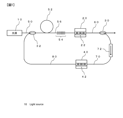
[0012] Fig. 1
is a diagram showing a configuration of a
light source device according to a first embodiment; and
Fig. 2 is a diagram showing a configuration of a light
source device according to a second embodiment.
3
CA 02850921 2014-04-02
BEST MODE FOR CARRYING OUT THE INVENTION
[0013] Embodiments of the present invention are now
described hereinafter with reference to the drawings. The
same reference numerals are used to indicate the same
components throughout the drawings, and therefore descriptions
thereof are omitted accordingly.
[0014] (First Embodiment)
Fig. 1 is a diagram showing a configuration of a light
source device according to a first embodiment. This
light
source device is used as, for example, a light source for
spectroscopic analysis, a light source of an interferometer,
or a light source of pump light for generating an
electromagnetic wave. This
light source device has a light
source 10, a first polarization-reversed structure 22 (a first
wavelength converter), a fiber coupler 30 (a dividing portion),
and a second polarization-reversed structure 42 (a second
wavelength converter). The
light source 10 emits first
incident light to the first polarization-reversed structure 22.
The first polarization-reversed structure 22 converts the
first incident light to emit a higher harmonic wave. The
fiber coupler 30 divides the higher harmonic wave output from
the first polarization-reversed structure 22 into output light
to be emitted from the light source device and feed back light.
The feedback light enters the second polarization-reversed
structure 42. The
second polarization-reversed structure 42
converts the wavelength of the feedback light to emit second
4
= CA 02850921 2014-04-02
incident light. The
second incident light has the same
wavelength as the first incident light. The second incident
light enters the first wavelength converter. The
details of
this configuration are described hereinbelow.
[0015] The
light source 10 is, for example, a laser diode.
This laser diode has a transmission wavelength of, for example,
980 nm, although it is not limited thereto. Light
that is
output from the light source 10 enters the first polarization-
reversed structure 22 through an optical fiber 50, a rare-
earth doped fiber 52, and an optical fiber 56. The
optical
fibers 50, 56 and the rare-earth doped fiber 52 are
polarization-maintaining optical fibers. The rare-earth doped
fiber 52 is used as a gain medium of a laser beam. The
optical fiber 56 has an FBG (fiber Bragg grating) 54. The
first incident light emitted from the light source 10
resonates between the light source 10 and the FBG 54 and is
emitted as a laser beam to the first polarization-reversed
structure 22. In
other words, the light source of the light
source device has a fiber resonator.
[0016] The first polarization-reversed structure 22 is
formed in a wavelength conversion element 20. The wavelength
conversion element 20 is formed using, for example,
ferroelectric crystal. This ferroelectric crystal is, but not
limited to, for example, LiNb03 added with Mg. A waveguide is
formed in the ferroelectric crystal. The
structure of the
waveguide is not limited to a particular structure. For
= CA 02850921 2014-04-02
instance, the waveguide may have a ridge structure or an
embedding structure. The
first polarization-reversed
structure 22 is provided in this waveguide. The
first
polarization-reversed structure 22 is a pseudo phase matching
element. The
polarization reversal cycle of the first
polarization-reversed structure 22 is defined in such a manner
as to generate a higher harmonic wave of first input light
that enters the wavelength conversion element 20. For example,
the first polarization-reversed structure 22 is defined in
such a manner as to generate a second higher harmonic wave of
the first incident light.
[0017] Output
light from the wavelength conversion element
20 is emitted through an optical fiber 60 in the form of the
output light emitted from the light source device. The
optical fiber 60 is a polarization-maintaining optical fiber.
The optical fiber 60 is provided with the fiber coupler 30.
The fiber coupler 30 divides the output light into the output
light emitted from the light source device and feedback light.
[0018] The
feedback light obtained at the fiber coupler 30
enters the second polarization-reversed structure 42 via an
optical fiber 70. The
optical fiber 70 is a polarization-
maintaining optical fiber. It
should be noted that the
optical fiber 70 is provided with an isolator 72. Light
coming from the wavelength conversion element 20 toward the
second polarization-reversed structure 42 passes through the
isolator 72.
CA 02850921 2014-04-02
[0019] The
second polarization-reversed structure 42 is
formed in a wavelength conversion element 40. The wavelength
conversion element 40 is formed using, for example,
ferroelectric crystal. This ferroelectric crystal is, but not
limited to, for example, LiNb03 added with Mg. A waveguide is
formed in the ferroelectric crystal. The
structure of the
waveguide is not limited to a particular structure. For
instance, the waveguide may have a ridge structure or an
embedding structure. The
second polarization-reversed
structure 42 is provided in this waveguide. The
second
polarization-reversed structure 42 is a pseudo phase matching
element. The
polarization reversal cycle of the second
polarization-reversed structure 42 is defined in such a manner
as to convert the feedback light (i.e., the higher harmonic
wave of the first input light) into light having the same
wavelength as the first input light (second incident light).
For example, when the first incident light is a second higher
harmonic wave of the first incident light, the second
polarization-reversed structure 42 is defined in such a manner
as to convert a degeneracy parameter of the second higher
harmonic wave (Optical Parametric Oscillate: OP0).
[0020] The
second incident light that is output from the
wavelength conversion element 40 enters the rare-earth doped
fiber 52 via an optical fiber 80 and a fiber coupler 32. The
optical fiber 80 is a pseudo phase matching element. The
fiber coupler 32 has two incidence portions. One of
the
7
CA 02850921 2014-04-02
incidence portions of the fiber coupler 32 is connected to the
optical fiber 50, and the other incidence portion to the
optical fiber 80. An output portion of the fiber coupler 32
is connected to the rare-earth doped fiber 52. In other words,
the second incident light enters the rare-earth doped fiber 52
along with the first incident light.
[0021] Here,
suppose that the length of an optical path
extending from the second polarization-reversed structure 42
to the first polarization-reversed structure 22 through the
optical fiber 80, the fiber coupler 32, and the rare-earth
doped fiber 52 (described as "first optical path,"
hereinafter) is 11. Also,
suppose that the length of an
optical path extending from the first polarization-reversed
structure 22 to the second polarization-reversed structure 42
through the optical fiber 60, the fiber coupler 30, and the
optical fiber 70 (described as "second optical path,"
hereinafter) is 12. The
lengths 11 and 12 satisfy the
relationship expressed in the following formula (1).
[0022]
n a,1
(1)
Aco 22a)
where n, represents a refractive index of the first
optical path obtained at the wavelength of the first incident
light, n2, a refractive index of the second optical path
obtained at the wavelength of the higher harmonic wave
generated by the first polarization-reversed structure 22, X,
8
CA 02850921 2014-04-02
the wavelength of the first incident light, k2,,, the wavelength
of the higher harmonic wave, and m an integer.
[0023) As a
result of satisfying the formula (1) shown
above, the phase of the first incident light and the phase of
the second incident light synchronize with each other at the
time when the first incident light and the second incident
light enter the first polarization-reversed structure 22. It
should be noted in the example shown in Fig. 1 that the phase
of the first incident light and the phase of the second
incident light are synchronized with each other as well at the
time when the first incident light and the second incident
light are multiplexed by the fiber coupler 32.
(0024) Note
that each optical fiber and the wavelength
conversion element 20 may be joined physically or combined
optically by means of a lens.
(0025) The
operations and effects of the present embodiment
are described next. The higher harmonic wave that is output
from the first polarization-reversed structure 22 has a narrow
line width because ASE (Amplified Spontaneous Emission) light
associated with the first incident light is removed therefrom.
For this reason, the second incident light generated from this
higher harmonic wave has a narrower line width than the first
incident light. Hence, the incident light that enters the
first polarization-reversed structure 22 has a narrow half
bandwidth. Therefore, the output light from the light source
device also has a narrow half bandwidth (line width).
9
CA 02850921 2014-04-02
[0026] The second incident light enters the rare-earth
doped fiber 52 along with the first incident light. Therefore,
the half bandwidth of a laser beam itself that enters the
wavelength conversion element 20 becomes narrow, making the
effects described above more remarkable.
[0027] When the phases of the first incident light and the
second incident light are not synchronized, the line width of
the output light from the light source device becomes wide.
In the present embodiment, however, the phase of the first
incident light and the phase of the second incident light are
synchronized with each other at the time when the first
incident light and the second incident light are multiplexed
by the fiber coupler 32. This makes the line width of the
output light from the light source devices even narrower.
[0028] The simple configuration of the light source device
leads to low cost of production of the light source device.
For example, the light source device shown in Fig. 1 does not
require any complicated control systems. Furthermore, the FBG
54 is provided in the optical fiber 56. The expensive rare-
earth doped fiber 52 does not have to be provided with an FBG.
Therefore, unlike a configuration in which an FBG is provided
in the rare-earth doped fiber 52, even if errors occur in the
production of the FBG 54, an increase in the production cost
of the light source device can be suppressed.
[0029] (Second Embodiment)
Fig. 2 is a diagram showing a configuration of a light
CA 02850921 2014-04-02
source device according to a second embodiment. The
light
source device according to this embodiment has the same
configuration as the light source device according to the
first embodiment except for the following features.
[0030] First,
the ferroelectric crystal of the wavelength
conversion element 20 has the second polarization-reversed
structure 42 in addition to the first polarization-reversed
structure 22. This ferroelectric crystal also has a dividing
waveguide 41 (a dividing portion). The dividing waveguide 41
has the incidence side thereof connected to the first
polarization-reversed structure 22 and the output side to the
optical fiber 60 and the second polarization-reversed
structure 42. The
dividing waveguide 41 divides a higher
harmonic wave emitted from the first polarization-reversed
structure 22 into output light emitted from the light source
device and feedback light. This feedback light is converted
into second incident light by the second polarization-reversed
structure 42.
[0031] The
second incident light that is emitted from the
second polarization-reversed structure 42 enters the fiber
coupler 32 via the isolator 72 and the optical fiber 80.
[0032] The
present embodiment, too, can provide the same
effects as the first embodiment. Moreover, because the first
polarization-reversed structure 22, the second polarization-
reversed structure 42, and the dividing portion are provided
in a single ferroelectric crystal, the size of the light
11
CA 02850921 2014-04-02
source device according to the present embodiment can be made
small.
[0033] The embodiments of the present invention are
described above with reference to the drawings; however, these
embodiments are merely illustrative of the present invention,
and therefore various other configurations can be adopted.
For instance, in the first and second embodiments, a
wavelength conversion element based on other principles may be
used in place of the first polarization-reversed structure 22
and the second polarization-reversed structure 42.
[0034] This application claims priority from Japanese
Patent Application No. 2011-246396 filed on November 10, 2011,
the entire content of which is incorporated herein by
reference.
12