Note: Descriptions are shown in the official language in which they were submitted.
CA 02850946 2014-05-05
. '
'
IMPROVED MANDIBULAR REPOSITIONING DEVICE
BACKGROUND OF THE INVENTION
1.1 (1) FIELD OF THE INVENTION
The present technology relates to an intraoral orthosis device for preventing
and/or treating snoring and/or obstructive sleep apnea. In particular, the
present technology
relates to a mandibular repositioning device (MRD) or Mandibular advancement
device
(MAD) for treating and/or preventing snoring and/or obstructive sleep apnea.
1.2 (2) DESCRIPTION OF THE RELATED ART
The respiratory system of the body facilitates gas exchange. The nose and
mouth form the entrance to the airways of a patient.
The airways include a series of branching tubes, which become narrower,
shorter and more numerous as they penetrate deeper into the lung. The prime
function of the
lung is gas exchange, allowing oxygen to move from the air into the venous
blood and
carbon dioxide to move out. The trachea divides into right and left main
bronchi, which
further divide eventually into terminal bronchioles. The bronchi make up the
conducting
airways, and do not take part in gas exchange. Further divisions of the
airways lead to the
respiratory bronchioles, and eventually to the alveoli. The alveolated region
of the lung is
where the gas exchange takes place, and is referred to as the respiratory
zone. (West,
"Respiratory physiology- the essentials").
Chronic snoring is a condition affecting a considerable proportion of the
population, estimated at 40% by some studies. During sleep, the patient's
throat muscles
relax, causing a narrowing of the pharynx. The consequence of this narrowing
is an
increase in the speed of the inhaled air caused by a venturi-type effect. The
air excites the
flexible part of the soft palate and uvula and these begin to vibrate noisily.
The noise created
in this way can reach up to 90 decibels.
Obstructive Sleep Apnea (OSA), a form of Sleep Disordered Breathing (SDB),
is characterized by occlusion of the upper air passage during sleep. It
results from a
1
i
CA 02850946 2014-05-05
combination of an abnormally small upper airway and the normal loss of muscle
tone in the
region of the tongue, soft palate and posterior oropharyngeal wall during
sleep. The
condition causes the affected patient to stop breathing for periods of at
least 10 seconds
duration, typically of 30 to 120 seconds duration, sometimes 200 to 300 times
per night.
The patient often resumes breathing in a sudden and noisy manner. It often
causes excessive
daytime somnolence, and it may cause cardiovascular disease and brain damage.
The
syndrome is a common disorder, particularly in middle aged overweight males,
although a
person affected may have no awareness of the problem. ( US Patent 4,944,310
(to
Sullivan).)
Therapy
Continuous Positive Airway Pressure (CPAP) therapy has been used to treat
Obstructive Sleep Apnea (OSA). The hypothesis is that continuous positive
airway pressure
acts as a pneumatic splint and may prevent upper airway occlusion by pushing
the soft
palate and tongue forward and away from the posterior oropharyngeal wall.
1.2.1 PAP Device
The air at positive pressure is typically supplied to the airway of a patient
by a
PAP device such as a motor-driven blower. The outlet of the blower is
connected via a
flexible delivery conduit to a patient interface that delivers the pressurized
air to the airways
of the patient. However, some patients do not tolerate CPAP therapy well and
so alternative
therapies are available.
1.2.2 Mandibular repositioning
A mandibular repositioning device (MRD) or mandibular advancement device
(MAD) is one of the treatment options for sleep apnea and snoring. It is an
adjustable intra-
oral appliance, available from a dentist or other supplier, which holds the
lower jaw
(mandible) in a forward position during sleep. The MAD is a removable device
that a
patient inserts into their mouth, prior to going to sleep, and removes,
following sleep. Thus,
the MAD is not designed to be worn all of the time. The MAD may be custom
made, or
produced in a standard form and include a bite impression portion designed to
allow fitting
to a patient's teeth. The mechanical protrusion of the lower jaw expands the
space behind
the tongue, puts tension on the pharyngeal walls to reduce collapse of the
airway and
2
CA 02850946 2014-05-05
=
diminish palate vibration.
A mandibular advancement device comprises an upper splint that is intended to
engage with or fit over teeth on the upper jaw (or maxilla) and a lower splint
that is intended
to engage with or fit over teeth on the upper jaw (or mandible). The upper and
lower splints
are connected together laterally via a pair of connecting rods. The pair of
connecting rods is
preferably fixed symmetrically on both sides of the jaw. Each rod is attached
to the upper
splint and the lower splint. Whilst each rod is generally attached to the
upper splint and the
lower splint at its respective ends, this does not have to be the case and the
attachment may
be effected by other portions of the rod.
The length of the connecting rods is selected such that when the MAD is placed
in a user's mouth the mandible is held in an advanced position. The length of
the connecting
rods may be adjusted to change the level of protrusion of the mandible. A
dentist may
determine a preferred level of protrusion for the mandible that will determine
the length of
the connecting rods.
Some MADs are structured to push the mandible forward relative to the maxilla
while other MADs, such as the ResMed Narval CCTM MAD, are designed to retain
the
mandible in a forward position. This device also reduces or minimises dental
and temporo-
mandibular joint (TMJ) side effects. Thus, it is configured to prevent or at
least minimise
any movement of one or more of the teeth caused by the applied pressure. For
instance,
document US2005016547 discloses a MAD with an upper groove and a lower groove
designed to line respectively with the upper jaw and the lower jaw. The
grooves are linked
together by two tie rods of such length that the lower jaw is maintained in an
extended
position relative to the upper jaw.
1.2.3 Bruxism treatment
Bruxism is the excessive grinding of the teeth and/or excessive clenching of
the
jaw. Some treatment devices known as occlusal splints cover the teeth of the
upper and/or
lower jaw to mechanically protect them. There are available intra-oral devices
including
partial or full-coverage splints, i.e. splints fitting over some or all of the
teeth. They are
typically made of plastic (e.g. acrylic) and can be hard or soft. A lower
appliance can be
worn alone, or in combination with an upper appliance.
3
CA 02850946 2014-05-05
BRIEF SUMMARY OF THE TECHNOLOGY
The present technology is directed towards a mandibular repositioning device
used in the amelioration, treatment, or prevention of snoring or obstructive
sleep apnea
having either one or more of improved comfort, cost, efficacy, retention, ease
of use and
manufacturability, or at least providing a useful alternative to existing
devices.
A first aspect of the present technology relates to an apparatus used in the
amelioration, treatment or prevention of snoring and/or obstructive sleep
apnea by
repositioning the lower jaw of a user in a forward position.
One form of the present technology comprises a mandibular advancement
device or intra-oral device that is configured for comfortable use by the
user.
Another aspect of one form of the present technology is a mandibular
advancement device having thickness of at least one gutter portion which
varies across the
profile of the teeth. This is to say that the cross-section of the gutter
portion may have
variable thickness. Preferably a retention portion and its profile are
structured to match the
profile of the teeth.
Another aspect of one form of the present technology is a method of designing
a
mandibular advancement device (MAD) using a computer aided design process,
wherein
the MAD is designed to include a retention profile calculated based on the
area of a
patient's teeth available for gripping.
Another aspect of one form of the present technology is a mandibular
advancement device having a gutter portion designed to grip over a plurality
of teeth to
retain the device on the jaw.
One form of the present technology comprises a mandibular advancement
device that provides a strong grip, reduced pressure on the teeth and/or a
substantial
elasticity.
Another aspect of one form of the present technology is the curved lower end
of
gutter edges on the splints, preferably improving comfort.
One form of the present technology comprises an angled band portion, which
4
CA 02850946 2014-05-05
may be inclined relative to a plane perpendicular to the sliding plane and
along the axis of
insertion. The band portion may be angled to follow the angle of the incisors
to reduce
protrusion into the inside of the lips.
One form of the present technology comprises a slot angled to prevent or
minimise unclipping of the connecting rods during cleaning. The angle of the
slot may be
designed relative to the axis of the connecting rod and may be adjustable.
Another aspect of one form of the present technology is an MAD including a
connection point on a lower splint that is structured to support the mucosa of
the cheek.
One form of the present technology comprises a connecting rod slot counter
sunk within elevated connection point of the lower splint.
Another aspect of the present technology relates to using a version of the
intra-oral
described herein to treat Bruxism. The intera-oral device may include no or
only minor
adjustments for use to treat Bruxism.
One form of the present technology comprises an intra-oral device having upper
and lower
splints that cover all or most of the teeth and are coupled together via rods
that are set at no
or 0 protrusion to treat Bruxism. The lower splint may include wings or
triangular portions
from which the rods are attached.
In another form of the present technology is an intra-oral device comprising
separate upper
and lower splints that cover all or most of the teeth, wherein the splints are
not coupled
together (i.e. no rods are attached between the upper and lower splints).
In a further form of the present technology is an intra-oral device adapted to
simultaneously
protrude the lower jaw forward to treat sleep disordered breathing and to
cover all or most
of the teeth to treat or prevent Bruxism.
As referred to herein, a neutral position of the mandible relative to the
maxilla is the natural
closing position. In other words the mandible in not forced or repositioned to
an advanced
position and is not forced or repositioned by the device to an retracted
position as generally
seen in a direction parallel to the oclussal plane. A neutral position is a
position with an
advancement of about 0 mm. If the user does not suffer from a sleep disorder
such as sleep
CA 02850946 2014-05-05
apnea, a neutral position may be appropriate to avoid or reduce bruxism
without the
discomfort caused by advancing the mandibular. On the other hand, if both
bruxism and
sleep apneas are to be treated a device adapted to cause an advanced position
of the
mandibular may be suitable.
Of course, portions of the aspects may form sub-aspects of the present
technology. Also, various ones of the sub-aspects and/or aspects may be
combined in
various manners and also constitute additional aspects or sub-aspects of the
present
technology. Alternatively or additionally, the disclosed technology could also
be described
by one or several of the following aspects. In particular, an aspect with a
preferred back-
reference to one or more other aspects may also be understood as an
independent aspect.
la. An intra-oral device, preferably designed to fit in a patient's
mouth, comprising:
an upper splint (7100), preferably structured to engage with at least a
portion of one or more
teeth on the maxilla, wherein the upper splint (7100) includes at least one
upper gutter
portion (7110), that preferably engages with a porfion of one or more teeth on
the maxilla,
to retain the upper splint on the maxilla; and/or
a lower splint (7200), preferably structured to engage with at least a portion
of one or more
teeth on the mandible,
wherein the lower splint (7200) include at least one lower gutter portion
(7210), that
preferably engages with a portion of one or more teeth on the mandible, to
retain the lower
splint on the mandible.
lb. The intra-oral device of aspect I a, wherein the device is a
mandibular device
and/or a bruxim splint.
lc. The intra-oral device of aspect 1 a or lb, wherein the device
comprises the upper
splint (7100), the lower splint (7200), and a pair of lateral connecting rods
(7300), each
connecting rod having a first rod end (7310) that connects to the lower splint
and a second
rod end (7320) that connects to the upper splint, preferably such that, in use
when the user's
mouth is closed, the connecting rods are positioned parallel to the Frankfort
plane.
6
CA 02850946 2014-05-05
ld. The intra-oral device of any one of aspects la to lcõ wherein the
connecting
rods (7300) are configured to maintain the mandible in a neutral position
relative to the
maxilla.
le. The intra-oral device of any one of aspects 1 a to ld, wherein the
connecting
rods (7300) are configured to maintain the mandible in an advanced position
relative to the
maxilla.
lf. The intra-oral device of any one of aspects la to ld, wherein the
upper splint
(7100) is adapted to cover all teeth of the respective upper jaw and/or the
lower splint
(7200) is adapted to cover all teeth of the respective lower jaw.
2a.An intra-oral mandibular advancement device, preferably designed to fit in
a patient's
mouth, comprising:
an upper splint (7100), preferably structured to engage with at least a
portion of one or
more teeth on the maxilla;
a lower splint (7200), preferably structured to engage with at least a portion
of one or
more teeth on the mandible; and
a pair of lateral connecting rods (7300), each connecting rod having a first
rod end
(7310) that connects to the lower splint and a second rod end (7320) that
connects to
the upper splint, preferably such that, in use when the user's mouth is
closed, the
connecting rods are positioned parallel to the Frankfort plane, wherein the
connecting
rods are configured to maintain the mandible in an advanced position relative
to the
maxilla,
wherein the upper splint includes at least one upper gutter portion (7110),
that
preferably engages with a portion of one or more teeth on the maxilla, to
retain the
upper splint on the maxilla,
wherein the lower splint include at least one lower gutter portion (7210),
that
preferably engages with a portion of one or more teeth on the mandible, to
retain the
lower splint on the mandible.
2b. The intra-oral mandibular device according to aspect 1, wherein the
thickness of the at
7
CA 02850946 2014-05-05
least one upper gutter portion and/or the at least one lower gutter portion
varies across
the profile of at least a portion of one or more teeth.
2c. The intra-oral device according to any one of aspects la to lf or 2a,
wherein a retention
portion of at least one of the at least one upper gutter portion and the at
least one lower
gutter portion has a varied thickness profile.
3. The intra-oral device according to any one of aspects 1 a to lf or to
2a, 2b or 2c,
wherein the at least one upper gutter portion is profiled to match the
contours of the at
least a portion of one or more teeth on the maxilla to improve retention of
the upper
splint.
4. The intra-oral device according to any one of the preceding aspects,
wherein the at least
one lower gutter portion is profiled to match the contours of the at least a
portion of the
one or more teeth on the mandible to improve retention of the lower splint.
5. The intra-oral device according to any one of aspects 2 to 4, wherein
the retention
portion is structured to match the profile of the at least a portion of the
one or more
teeth on the maxilla or mandible.
6. The intra-oral device according to any one of the preceding aspects,
wherein the
retention portion extends along the crown region of the at least a portion of
the one or
more teeth engaged by the gutter portion.
7. The intra-oral device according to aspect 6, wherein the retention
portion is located at a
side portion of the crown region.
8. The intra-oral device according to any one of the preceding aspects,
wherein the at least
one upper gutter portion, which is preferably adapted to elastically clip on
at least one
tooth or at least a portion of one or more teeth located in the upper gutter
portion,
and/or the at least one lower gutter portion is adapted to elastically clip on
at least one
tooth or at least a portion of one or more teeth located in the lower gutter
portion.
8
CA 02850946 2014-05-05
9. The intra-oral device according to any one of the preceding aspects,
wherein the at least
one upper gutter portion and/or the at least one lower gutter portion each
comprise, at
the inner side wall facing the at least one tooth or at least a portion of one
or more
teeth, at least one undercut portion (7266), the undercut portion (7266) being
adapted to
hold the device on the tooth or at least a portion of one or more teeth, at
least to support
at least one of the retention or clipping of the device.
10. The intra-oral device according to aspect 9, wherein the undercut portion
extends
substantially along the tooth's side wall (b) from an apex (a) of the tooth's
side wall (b)
in an inward direction towards the gingival part of the tooth.
11. The intra-oral device according to aspect 9 or 10, wherein the undercut
portion defines
an undercut (u), the undercut (u) preferably being adapted to interlock the
respective
upper splint and/or lower splint to the at least one tooth or at least a
portion of one or
more teeth on the maxilla or mandible respectively.
12. The intra-oral device according to any one of the preceding aspects,
wherein the at least
one upper gutter portion (7110) and/or the at least one lower gutter portion
(7210)
comprise(s) a sliding plane surface (7160,7260).
12a. The intra-oral device of aspect 12, wherein the sliding plane surface
(7160, 7260) of
one of the upper and lower gutter portions (7110, 7210) is in contact with the
other
of the upper and lower gutter portions (7110, 7210).
12b The intra-oral device of aspect 12 or 12a, wherein the sliding plane
surface (7160,
7260) is substantial flat and, in use, is substantially parallel to the
occlusal plane.
12c The intra-oral device of aspect 12, 12a or 12b, wherein the sliding
plane surface
extends along a major part or the entire width of the tooth.
12d The intra-oral device of ane one of aspects 12 to 12c, wherein the
sliding plane
surface extends along the tooth or at least a portion of one or more teeth in
a cross
sectional view of the gutter portion.
9
CA 02850946 2014-05-05
13. The intra-oral device according to aspect 12, wherein the sliding plane
surface joins the
side wall of the respective gutter portion (7110, 7210) in at least one first
joining
section (7264), and wherein the thickness (EPa) of the side wall of the
respective gutter
portion (7110, 7210) in the area of the apex (a) of the tooth or at least a
portion of one
or more teeth is reduced compared to the thickness (EPj) of the side wall in
the first
joining section.
14. The intra-oral device according to any one of the preceding aspects,
wherein the
undercut portion intersects with an inner receiving portion (7268) of the side
wall of the
respective gutter portion (7110, 7210) in a second joining section (7269).
15. The intra-oral device according aspect 14, wherein the thickness (EPa) of
the side wall
of the respective gutter portion (7110, 7210) in the area of the apex (a) of
the tooth or at
least a portion of one or more teeth is reduced compared to at least one of
the thickness
(EP1) of the side wall in the second joining section and the thickness (EPm)
of the side
wall of the inner receiving portion.
16. The intra-oral device according aspect 14 or 15, wherein the inner
receiving portion
may angle outwardly and, in use, away from the gingival part.
17. The intra-oral device according to any one of the preceding aspects,
wherein the lower
splint includes a lower splint connection point (7230) for connection of the
first rod end
(7310).
18. The intra-oral device according to aspect 17, wherein the lower splint
connection point
is elevated in the application position relative to the major part of the
lower splint
and/or relative to the at least a portion of one or more lower teeth.
19. The intra-oral device according to any one of the preceding aspects,
wherein the lower
splint connection point (7230) includes a first slot (7232) and/or the first
rod end (7310)
includes a first rod pin (7312) configured to be received in the first slot.
CA 02850946 2014-05-05
20. The intra-oral device preferably according to aspect 19, wherein, in a
closed
configuration of the device, the longitudinal axis of the first slot and the
longitudinal
axis of the connecting rod are arranged in a first obtuse angle (a).
21. The intra-oral device according to any one of the preceding aspects,
wherein the upper
splint includes an upper splint connection point (7130) for connection of the
second rod
end (7320).
22. The intra-oral device according to aspect 21, wherein the upper splint
connection point
(7130) includes a second slot (7132) and/or the second rod end (7320) includes
a
second rod pin (7322) configured to be received in the second slot.
23. The intra-oral device preferably according to aspect 22, wherein, in a
closed
configuration of the device, the longitudinal axis of the second slot and the
longitudinal
axis of the connecting rod are arranged in a second obtuse angle (0).
24. The intra-oral device preferably according to any one of aspects 19 to 23,
wherein the
first slot is counter sunk on the lower splint connection point.
25. The intra-oral mandibular advancement device preferably according to any
one of
aspects 19 to 24 wherein the second slot is counter sunk on the upper splint
connection
point.
26. The intra-oral device preferably according to any one of the preceding
aspects, where
the angle of the longitudinal axis of the first slot to the sliding plane
and/or the angle of
the longitudinal axis of the second slot to the sliding plane is adjustable.
27. The intra-oral mandibular advancement device according to any one of the
preceding
aspects, including at least one of
(i) an upper band portion (7120) between two upper gutter portions on the
upper
splint; or
11
CA 02850946 2014-05-05
(ii) a lower band (7220) between two lower gutter portions on the lower
splint.
28. The intra-oral device according to aspect 27, wherein the upper band
portion and/or
lower band portion each comprise(s) a rounded edge on at least one of the top
or
bottom edge(s).
29. The intra-oral device according to aspect 28, wherein the rounded edge(s)
comprise a
drop shape.
30. The intra-oral device according to any one of aspects 27 to 29, wherein at
least one of
the upper band portion andlower band portion is inclined to follow the angle
of the
patient's incisors.
31. The intra-oral device according to any one of the preceding aspects,
wherein the lower
splint connection point is located in a wing structure (7240) with a wing base
(7242)
extending laterally from the lower gutter portion.
32. The intra-oral device according to aspect 31, wherein the wing structure
comprises a
filled portion (7243) connecting the laterally extending wing base to the
respective
portion of the lower gutter portion, the filled portion being contoured to
provide
support to the cheek and to avoid dead space between the wing structure and
the cheek.
33. The intra-oral device according to aspect 31 or 32, wherein the
length of the wing base
and of the filled portion is selected so as to avoid edges, curvatures with
small radii and
dead space between the wing structure and the check.
34. Method of designing an intra-oral device using computer aided design
process, the
computer having a processor, the processor configured to perform the method
including
the steps of:
obtaining an electronic image of a patient's dental arch including at least
one of at
least a portion of one or more of the teeth on the maxilla and at least a
portion of one
12
CA 02850946 2014-05-05
or more of the teeth on the mandible;
processing the received image to:
determine a retention portion or area on a crown region of at least a portion
of
one or more teeth available for gripping or clipping;
calculate a retention profile based on the determined retention portion or
area to
spread the load of retention across the at least a portion of one or more
teeth
available for gripping or clipping; and
design a intra-oral device having an upper splint and a lower splint and a
pair of
lateral connecting rods connecting the upper and lower splints,
wherein at least one of the upper splint andthe lower splint includes the
calculated
retention profile.
35. Method according to aspect 34, wherein the retention profile is determined
on the side
portion of the crown region of at least a portion of one or more teeth
available for
gripping.
36. Method according to any one of aspects 34-35, wherein the at least a
portion of the
teeth available for gripping includes at least one of:
(i) the teeth between the second molar and the canines on each side of the
mandible;
(ii) a plurality of teeth located between the first molar and the canines on
each side
of the mandible;
(iii) the teeth between the second molar and the canines on each side of the
maxilla;
Or
(iv) a plurality of teeth located between the first molar and the canines on
each side
of the maxilla.
37. Method according to any one of aspects 34-36, comprising determining an
undercut
portion of the at least a portion of the one or more teeth and calculating an
undercut
13
CA 02850946 2014-05-05
portion of the profile.
38. Method according to aspect 37, wherein the undercut portion is determined
on the basis
of the apex (a) of the sidewall of the at least a portion of the one or more
teeth and of a
minimum distance to the gingival part of the at least a portion of the one or
more teeth.
39. Method according to aspect 38, wherein the determination of the apex (a)
is based on at
least one of the direction of insertion (I) of the at least a portion of the
one or more
teeth into the respective gutter portion, the inserted shape of the at least a
portion of the
one or more teeth, or the height of the at least a portion of the one or more
teeth.
40. Method according to any one of aspects 37-39, wherein the thickness (EP)
of the
profile is calculated on the basis of the determined undercut portion so as to
provide an
elastic gutter side walls adapted to clip on the at least a portion of the one
or more teeth.
41. Method according to any one of aspects 34-40, wherein an inner receiving
portion
(7268) of the profile is located in the application position adjacent to the
gingival part,
the inner receiving portion (7268) being arranged at a minimum distance to the
gingival part.
42. Method according to any one of aspects 34-41, further comprising
manufacturing the
device according to the design.
43. Method according to any one of aspects 34 to 42 wherein the device is
manufactured
using a computer aided manufacturing technique.
Other features of the technology will be apparent from consideration of the
information contained in the following detailed description, abstract,
drawings and claims.
BRIEF DESCRIPTION OF THE SEVERAL VIEWS OF THE DRAWINGS
The present technology is illustrated by way of example, and not by way of
14
CA 02850946 2014-05-05
limitation, in the figures of the accompanying drawings, in which like
reference numerals
refer to similar elements including:
1.3 THERAPY
1.3.1 Respiratory system
Fig. la shows a blocked airway due to the collapse of the muscles in the upper
airway blocking the upper airway.
Fig. lb shows how protrusion of the lower jaw expands the space behind the
tongue to prevent or reduce blockage of the upper airway.
Fig. 2a shows an overview of a human respiratory system including the nasal
and oral cavities, the larynx, vocal folds, oesophagus, trachea, bronchus,
lung, alveolar sacs,
heart and diaphragm.
Fig. 2b shows a view of a human upper airway including the nasal cavity, nasal
bone, lateral nasal cartilage, greater alar cartilage, nostril, lip superior,
lip inferior, larynx,
hard palate, soft palate, oropharynx, tongue, epiglottis, vocal folds,
oesophagus and trachea.
1.3.2 Mouth Anatomy
Fig. 3 shows an anterolateral view of an open human mouth showing the
arrangement of the teeth on the maxilla and mandible jaws.
Fig. 4 shows a frontal (Antero-Posterior) view of an open human mouth
showing the arrangement of the teeth on the maxilla and mandible jaws.
Fig. 5a shows a side view of a human face indicating the Frankfort horizontal
plane
Fig. 5b shows an anterolateral view of a closed human mouth with a line
indicating the occlusal plane.
1.4 BREATHING WAVEFORMS
Fig. 6a shows a model typical breath waveform of a person while sleeping, the
CA 02850946 2014-05-05
horizontal axis is time, and the vertical axis is respiratory flow. While the
parameter values
may vary, a typical breath may have the following approximate values: tidal
volume, Vt,
0.5L, inhalation time, Ti, 1.6s, peak inspiratory flow, Qpeak, 0.4 L/s,
exhalation time, Te,
2.4s, peak expiratory flow, Qpeak, -0.5 L/s. The total duration of the breath,
Ttot, is about
4s. The person typically breathes at a rate of about 15 breaths per minute
(BPM), with
Ventilation, Vent, about 7.5 L/s. A typical duty cycle, the ratio of Ti to
Ttot is about 40%.
Fig. 6b shows polysomnography of a patient before treatment. There are eleven
signal channels from top to bottom with a 6 minute horizontal span. The top
two channels
both are EEG (electoencephalogram) from different scalp locations. Periodic
spikes in
second represent cortical arousal and related activity. The third channel down
is submental
EMG (electromyogram). Increasing activity around time of arousals represent
genioglossus
recruitment. The fourth & fifth channels are EOG (electro-oculogram). The
sixth channel is
an electocardiogram. The seventh channel shows pulse oximetry (Sp02) with
repetitive
desaturations to below 70% from about 90%. The eighth channel is respiratory
airflow
using nasal cannula connected to differential pressure transducer. Repetitive
apneas of 25 to
35 seconds alternating with 10 to 15 second bursts of recovery breathing
coinciding with
EEG arousal and increased EMG activity. The ninth shows movement of chest and
tenth
shows movement of abdomen. The abdomen shows a crescendo of movement over the
length of the apnea leading to the arousal. Both become untidy during the
arousal due to
gross body movement during recovery hyperpnea. The apneas are therefore
obstructive, and
the condition is severe. The lowest channel is posture, and in this example it
does not show
change.
Fig. 6c shows patient flow data where the patient is experiencing a series of
total obstructive apneas. The duration of the recording is approximately 160
seconds. Flow
ranges from about +1 Lis to about -1.5L/s. Each apnea lasts approximately 10-
15s.
Fig. 6d shows a scaled inspiratory portion of a breath showing a low frequency
snore.
1.5 INTRA-ORAL DEVICE
Figs. 7a to f show a intra-oral device in front views and perspective views.
16
CA 02850946 2014-05-05
Figs. 8a to e show side views of the upper and lower splints of a Mandibular
advancement device (MAD).
Fig. 9a shows an inclined mandible band portion of a lower splint.
Fig. 9b shows the profile of the mandible band portion respectively of an MAD.
Figs. 10a and 10b show side views of a lower splint of an MAD.
Fig. 10c shows a back view of a lower splint.
Fig. 10d shows a side view of an upper splint.
Fig. 10e shows a side view of a connecting rod.
Fig. 10f shows a perspective view of a connecting rod.
Fig. lla shows a perspective view of a lower splint.
Fig. 1 lb shows a cross section of the mandible gutter portion shown in Fig.
lla.
Fig. 12a shows a cross sectional view of a lower gutter portion engaged with a
tooth.
Fig. 12b shows an enlarged view of a part of Fig. 12a.
Fig. 12c shows another cross sectional view similar to Fig. 12a.
Fig. 12d shows a cross sectional view of a upper gutter portion engaged with a
tooth.
Fig. 13 shows a process for designing a MAD having improved retention using a
computer aided design process.
Figs. 14 and 15 show further views of MAD according to the present technology.
DETAILED DESCRIPTION OF EXAMPLES OF THE TECHNOLOGY
Before the present technology is described in further detail, it is to be
understood that the technology is not limited to the particular examples
described herein,
which may vary. It is also to be understood that the terminology used in this
disclosure is for
17
CA 02850946 2014-05-05
the purpose of describing only the particular examples discussed herein, and
is not intended
to be limiting.
1.6 INTRA-ORAL DEVICE 7000
Fig. 7a discloses an intra-oral device or a mandibular advancement device
(MAD) 7000 fitted over a mould of an upper jaw and lower jaw including teeth.
The intra-
oral device or MAD comprises an upper splint 7100, a lower splint 7200 and a
pair of
connecting rods 7300 connecting the upper and lower splints 7100, 7200
together.
As seen in Figs. 7a to 8e, the upper splint 7100 includes two maxilla or upper
gutter portions 7110 designed or structured to fit over at least a portion of
one or more teeth
on each side of the maxilla or upper jaw. The upper gutter portions 7110 may
cover a
plurality of teeth in the region between the molars and canine on the maxilla.
A maxilla or
upper band portion 7120 is preferably provided between the two upper gutter
portions 7110
to join the two upper gutter portions 7110 together. The upper band portion
7120 may be
designed to extend between the two upper gutter portions 7110 across the front
portion of
the lateral and central incisors and may not engage with the internal or the
external surface
of these incisor teeth. Here, the upper band portion 7120 reduces the visual
impact of the
upper splint when inserted within the patient's mouth. Preferably, the upper
splint 7100 is
formed as a single piece with the upper gutter portions 7110 and the upper
band portion
7120 integrally formed together.
However, it is noted that the upper splint 7100 may include a single upper
gutter
portion 7110 designed to fit over all of the teeth of the maxilla, thus no
upper band portion
7120 would be required in such an upper splint. Such an upper splint may be
more intrusive
within the mouth. Such an upper splint may be used when the splint is used to
treat
Bruxism alone or simultaneously with treating obstructive sleep apnea.
The upper splint 7100 also may include one or more, but preferably a pair of
upper splint
connection points 7130, preferably one on each side of the upper splint 7100,
to allow
connection of a respective second rod end 7320 of each one of the pair of
connecting rods
7300, to the upper splint 7100. As illustrated in Figs. 7a and 8e, the upper
splint connection
points 7130 are preferably provided in the region of the canines. Preferably,
the upper splint
connection points 7130 are made as small as possible and may include a rounded
shape to
18
CA 02850946 2014-05-05
prevent irritation within the mouth. Preferably, the shape and size of the
contact surface of
the upper splint connection point 7130 substantially correspond to the shape
and size of the
second rod end 7320 (see Figs. 7a to 7f and Figs. 8a to 8e).
The lower splint 7200, as illustrated in Figs. 7a to 8e, includes two mandible
or
lower gutter portions 7210 designed to fit over at least a portion of one or
more teeth on
each side of the mandible. The lower gutter portions 7210 may cover a
plurality of teeth in
the region between the molars and canine on the mandible. A mandible or lower
band
portion 7220 is preferably provided between the two lower gutter portions 7210
to join the
two lower gutter portions 7210 together. The lower band portion 7220 may be
designed to
extend between the two lower gutter portions 7210 across the front portion of
the lateral and
central incisors and may not engage with the internal or the external surface
of these incisor
teeth. Here, the lower band portion 7220 reduces the visual impact of the
lower splint 7200
when inserted within the patient's mouth. Preferably, the lower splint 7200 is
formed as a
single piece with the two lower gutter portions 7210 and the lower band
portion 7220
integrally formed together.
However, it is noted that the lower splint 7200 may include a single lower
gutter
portion 7210 designed to fit over all of the teeth of the mandible
respectively, thus no lower
band portion 7220 is required in such a lower splint. Such a lower splint may
be more
intrusive within the mouth. Such a lower splint may be used when the splint is
used to treat
Bruxism alone or simultaneously with treating obstructive sleep apnea.
As shown in Figs. 9a and 9b, the lower band portion 7220 may comprise
rounded or smoothed edges, including at least one of the top andbottom edges
to reduce or
prevent irritation to the teeth or gums on the mandible or maxilla. In one
arrangement, the
top edge 7222 or bottom edge 7224 or both may have a tear-drop or drop-shape.
Figs. 9a
and 9b depict the lower band portion. However, the upper band portion 7120 may
also be
configured in the same way as the lower band portion 7220 shown in Figs. 9a
and 9b, such
that it may include rounded or smoothed top edges or bottom edges or both.
Alternatively,
or additionally, the other outer edges 7118, 7218 (Figs. 11b, 12a) of the
upper or lower
splint, particularly the edges of the gutter portion, may have rounded,
smoothed or drop-
shaped as further described below.
19
CA 02850946 2014-05-05
As particularly seen in Fig. 8e, the lower band portion 7220 may be inclined
relative to a plane P-P perpendicular to the sliding plane surface 7160, 7260,
which is
parallel to the occlusal plane. The front surface 7220a of the lower band
portion 7220 is
inclined or angled (line Q-Q in Fig. 8e) to follow the angle of the incisors
to prevent
protrusion of the lower band portion 7220 into the inside of the lips. In
other words, the
front surface 7220a of the lower band portion 7220 angles slightly outwards
from the
bottom to the top in use. In a similar manner (as seen in Fig. 8e) the upper
band portion
7120 may also be angled to follow the angle of the patients incisors and may
include
rounded or smoothed top and bottom edges to reduce irritation of the maxilla
gums. Such a
design preferably prevents protruding too far inside of the lips. The band of
prior art device
can be located very far from the teeth in the case of angled incisors.
Vestibular bands may
be replaced by lingual bands and angles may be adjustable parameters. It is
appreciated that
the upper band portion 7120 or the lower band portion 7220 as such may be
provided with
different designs of MADs and the specific arrangement of other components
such as the
gutter portion design may vary.
As seen in Figs. 7a to 10b the lower splint 7200 also may include one or more
of
lower splint connection points 7230, preferably a pair of points, one on each
side of the
lower splint 7200. Each lower splint connection point 7230 may be configured
to allow
connection to a first end 7310 of a respective one of the pair of connecting
rods 7300 to the
lower splint 7200 (Figs. 7c, 7d and 8b) . The lower splint connection points
7230 may be
elevated relative to the lower gutter portions 7210. Preferably, the elevated
lower splint
connection points 7230 are adjacent the upper gutter portions 7110 on the
upper splint 7100
(Figs. 7d, 8a-1 to 8c). The lower splint connection point 7230 is preferably
provided in the
area of molars, such as the second molar (Fig. 10a). Thus, each one of the
pair of connecting
rods 7300 may be configured to substantially laterally connect the upper
splint 7100 and the
lower splint 7200, with the second end 7320 of the connecting rod 7300
connected to the
upper splint 7100 and the first end 7310 of the connecting rod 7300 connected
to the lower
splint 7200 (Figs. 7, 8). The lower splint connection points 7230 on the lower
splint 7200
may be elevated in a position so that when the connecting rods 7300 are
connected to the
upper splint 7100 and lower splint 7200 the connecting rods 7300 are
positioned
substantially parallel with the Frankfort plane. In such an arrangement the
traction force of
the connecting rods 7300 is substantially parallel to the occlusal plane,
which reduces the
CA 02850946 2014-05-05
likelihood of the intra-oral device or MAD coming loose in use. This
arrangement of the
connecting rods 7300 is also advantageous for retaining the mandible in an
advanced
position.
As particularly illustrated in Figs. 10a to 10c, each of the lower splint
connection points 7230 may be formed in a wing structure 7240 that protrudes
laterally
from the lower splint 7200. The wing structure 7240 may have a curved
structure to assist in
supporting a patient's mucosa of the cheek when the intra-oral device or MAD
is inserted in
the patient's mouth. The wing structure 7240 may comprise a curved structure
or filled
portion 7243 connecting the substantially laterally extending wing base 7242
to the
respective portion of the lower gutter portion (Fig. 10c). The filled portion
7243 is
preferably contoured to provide support to the cheek so as to avoid dead space
between the
wing structure 7240 / lower gutter portion 7220 and the mucosa of the cheek.
The filled
portion 7243 may extend from an outer side 7244 of the wing structure 7240
until the outer
edge 7218 of the respective gutter portion in a substantially flat or even a
slightly convex
fashion, preferably without a concave portion.
Prior art devices meet the gutter wall in a side wall portion located in the
middle
of the gutter side wall. This transition area at the middle side wall portion
overall has a
concave shape.
Preferably, the wing structure 7240 is contoured to avoid edges or curvatures
with small radii in order to avoid causing discomfort. Preferably, the length
of the wing base
7242 and of the filled portion 7243 parallel to the direction of extension of
the mandibular is
selected so as to avoid edges, curvatures with small radii and/or dead space
between the
wing structure 7240 / lower gutter portion and the mucosa of the check thereby
increasing
comfort. In other words, the wing structure may be less angular and the
merging with the
gutter may be optimized. The extremities of the wing structure may be slightly
curved.
Prior art devices comprise connection portions having a shape designed to be
able to withstand the applied force with the lowest material consumption
possible,
particularly since the material consumption increases the material costs and
production
time. Compared to prior art devices, wing base 7242 and filled portion 7243
are longer than
21
CA 02850946 2014-05-05
those prior art devices in order to avoid discomfort.
It is appreciated that the above wing structure and particularly the filled
portion
may also be provided with different designs of MADs and the specific
arrangement of other
components, such as the gutter or band portion design, may vary.
The wing structure may comprise an elevated portion 7245 elevating from the
wing base 7242 (Figs. 10a to 10c). Preferably, the lower splint connection
point 7230 is
located in the elevated portion 7245. The elevated portion 7245 may have a
triangular
configuration, although other shapes may be used. The lower splint connection
point 7230
may be counter sunk within the wing structure 7240 to reduce irritation of a
first attachment
or rod pin 7312 of the connecting rod 7300 in a patient's mouth when the
connecting rod
7300 is attached through the first slot 7232 (Fig. 10a) of the lower splint
connection point
7230 of the lower splint 7200 and the MAD is in a patient's mouth (Fig. 7).
Here, the
thickness of the elevated portion 7245 is adapted to accommodate a first rod
pin 7312 so
that the outer side or surface 7244 of wing structure 7240 is substantial
plane. This means
that preferably no portion or only a minor portion of the first rod pin 7312
protrudes from
the outer side or surface 7244. The first and second rod pins 7312, 7322 may
each comprise
at least one pin protrusion 7313, 7323 extending laterally from the upper end
of the rod
pin(Fig. 100. The lower splint connection point 7230 may comprise a recessed
portion
adapted to accommodate the at least one first pin protrusion 7313 (Fig.
10a).Preferably, the
recessed portion is adapted to accommodate rotation of the at least one first
pin protrusion
7313. The lower splint connection point 7230 may have a through hole with a
shape adapted
to the shape of the first attachment or rod pin 7312. The outer side 7244 may
be arranged
substantially parallel to an inner side. The inner side may be arranged as a
substantially flat
surface, preferably in an angle of (about) 900 to the wing base 7242 or the
occlusal or
sliding plane surface 7160, 7260 (Fig. 10c). This may improve the fixation of
the
connecting rod. The lower splint connection points 7230 of the lower splint
7200 may be
formed as first slots 7232 configured to receive the first rod pins 7312 of
the connecting
rods 7300 (see Fig. 10a).
It is appreciated that the counter sunk connection point as well as the inner
and
outer surface may also be provided with different designs of MADs and the
specific
arrangement of other components, such as the particular wing structure
arrangement in
22
CA 02850946 2014-05-05
general, may vary.
The upper splint connection point(s) 7130 of the upper splint 7100 may be
formed as second slot(s) 7132 configured to receive the second rod pin(s) 7322
of the
connecting rod(s) (Figs. 7, 8). Preferably, the first slots 7232 and the
second slots 7132 have
complementary shapes to the shapes of the first rod pins 7312 and second rod
pins 7322
respectively to facilitate insertion of the first rod pins 7312 and second rod
pins 7322 into
the first slots 7232 andthe second slots 7132, respectively. The first slots
7232 andsecond
slots 7132 are configured to allow the connecting rods 7300 to pivot or swivel
within the
slots 7132, 7232 in use to enable the opening and closing movement of the
mandible in use.
It is appreciated that the above described connection of the rod to the lower
splint(s) may also be provided with different designs of MADs and the specific
arrangement
of other components, such as the gutter or band portion design, may vary.
The assembly and disassembly of the connecting rods 7300 to the upper splint
7100 and lower splint 7200 will now be described in relation to the lower
splint using the
first slot 7232, the first rod pin 7312 and the lower connection point 7230.
However, it is to
be understood that the same process is used to assemble and disassemble the
upper splint
and the connecting rods using the second slot 7132, the second rod pin 7322
and the upper
connection point 7130. For assembly the first rod pins 7312 may be inserted
into and
through the first slot 7232 in the lower connecting point 7230 by aligning the
first rod pins
7312 with the first slots 7232. Once inserted the connecting rod 7300 is
rotated or pivoted
around in the first slot 7232 to prevent the first rod pins 7312 from
releasing out of the slot.
For disassembly of the connecting rods 7300 from the first slot 7232 the
connecting rod
7300 is preferably rotated or pivoted to realign the first rod pins 7312 with
the first slots
7232 to allow removal of the rod pins through the slot.
To avoid detachment of the connecting rods 7300 during use or for detachment
for cleaning the angle a, of the first andsecond slot(s) 7132, 7232 are
preferably set
relative to the axis of the connecting rod 7300 to ensure that there is an at
least one quarter
turn in order to disassemble the connecting rod 7300. For instance, an at
least one quarter
turn in the clockwise direction is to be ensured in Fig. 8c. The longitudinal
axis of the first
slot 7232 and the longitudinal axis of the connecting rod 7300 in use (i.e.
application by the
23
CA 02850946 2014-05-05
user with closed mouth) may be arranged in a first obtuse angle a. Preferably
the angle a is
in a range of 90 to 170 , more preferably of 1000 to 160 or of 1100 or 130
to 150 , and
most preferably of 105 to 135 (Fig. 8c) .
Preferably, the longitudinal axis of the second slot 7132 and the longitudinal
axis of the connecting rod 7300 in use (i.e. application by the user with
closed mouth) are
arranged in a second obtuse angle (0). Preferably, the second obtuse angle (0)
is in a range
of 90 to 170 , more preferably of 100 to 160 , or of 110 or 130 to 150
and most
preferably of 105 to 135 (Fig. 8c). The angles a and may have the same
value.
Moreover, angle a and/or 0 may preferably be 105 . An angle of the
longitudinal axis of
the first slot 7232 to the sliding plane surface 7260 or occlusal plane may be
adjustable.
Similarly, the angle of the longitudinal axis of the second slot 7132 to the
sliding plane
surface 7160 may also be adjustable. The angle may be adjusted considering the
relative
orientation of the connecting rod 7300 to the sliding plane surface 7160, 7260
or occlusal
plane. With such a tailored design parameter, the risk of an unintended
disassembly can be
further reduced.
It is appreciated that the above described angular relationship between the
longitudinal axis of the slots to the longitudinal axis of the connecting rod
in use may also
be provided with different designs of MADs and the specific arrangement of
other
components, such as the gutter or band portion design or the general wing
design, may vary.
Optionally, a flow sensor, pressure sensor, radio frequency identification
(RFID)
sensor or any other type of sensor may be incorporated into the MAD,
preferably in the
lower splint, most preferably into the wing structure 7240. The sensor
arrangement may be
the sensor arrangement as disclosed in the patent document EP 2575706. The
compliance
monitoring system and its sensors disclosed in EP 2575706 are part of the
described
technology and are incorporated here in its entirety by reference.
The outer side 7244 of the wing structure 7240 may also provide a surface for
insertion or engraving of a label such as an identification label, brand,
trademark, name,
number, code or similar such label. Alternatively, or additionally, the label
might be
engraved in the substantially flat upper or lower band portion or on any other
visible and
purposely flat/even designed portion such as a portion in the gutter region of
the upper
24
CA 02850946 2014-05-05
splint (Fig. 8). Engraving the label on the substantially flat portion, and
particularly in a
portion of the wing structure not interfering with the lower connecting point
7230, increases
the readability of the label. This particularly applies in comparison with
MADs having
labels on thin and uneven gutter walls.
It is appreciated that the engraving of a label may also be provided with
different designs of MADs and the specific arrangement of other components,
such as the
gutter or band portion design, may vary as long as the outer side of a wing
structure is
substantially flat.
The degree of advancement of the mandible may be defined by the length of the
connecting rods 7300. The connecting rods 7300 may be formed in a range of
lengths for
example in lengths from 20 mm to 40 mm, such as 21 mm to 36 mm, with
incrementing
sizes for example of 0.5 mm, 1 mm or 1.5 mm. The connecting rods 7300 may be
manually
attachable to and detachable from the splints 7100, 7200 to allow
interchanging of the
connecting rods 7300 for different lengths to adjust the level of mandible
advancement.
Alternatively the length of the connecting rods 7300 may be adjustable to
facilitate
adjustments in the level of mandible advancement as described in the US
7,146,982 the
contents of which is incorporated herein in its entirety.
As shown in Fig. 10f, each of the connecting rods 7300 may be removable and
replaceable and may include the first rod pin 7312 at the first end 7310, for
connection to
the lower splint connection point 7230 on the lower splint 7200, anda second
rod pin 7322
at the second end 7320 for connection to the upper splint connection point
7130 on the
upper splint 7100. In the application position, the first attachment or rod
pin 7312 may be
located and may protrude from an outer side of the connecting rod 7300 and the
second rod
pin 7322 may be located and may protrude from an opposing inner side of the
connecting
rod 7300. In this arrangement, each of the connecting rods 7300 may be
positioned between
the upper splint 7100 and the lower splint 7200, preferably between the upper
splint 7100
and the elevated splint connection point 7230 of the wing structure 7240. This
also
minimizes contact of the connecting rods 7300 with the mucosa of the cheek in
the patient's
mouth in use.
Figs. 11a, 1 lb and 12a-12c show, inter alia, the retention profile of at
least one
CA 02850946 2014-05-05
of the upper andlower gutter portions 7110, 7210. The gripping or clipping
features of the
lower gutter portion 7210 will now be described with reference to Figs 11 a,
11b, 12a-c.
However, it is acknowledge that the same or similar features as those
described below may
be applied to the at least one upper gutter portion as seen in Fig. 12d.
Moreover, the
discussion is focussed on one gutter portion. It is appreciated that the
described technology
also applies to a plurality of upper or lower gutter portions such as two
upper (i.e. left and
right upper gutter portion) and two lower (i.e. left and right lower gutter
portion) gutter
portions.
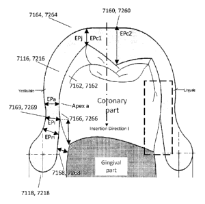
Fig. 1 lb shows a cross section of the mandible gutter portion. The thicker
inner line having
generally the same shape as the respective tooth, on which portion of the
lower gutter
portion is inserted, represents the retention portion 7261. An equivalent
retention portion
7161 may be present in the upper gutter portion (see Fig. 12d). The retention
portion may
also be named retention area. The profile of this retention portion 7261 is
the retention
profile. As can be seen in Figs. 11b, 12a-b, at least a portion of the area
over the arch of the
crown of the teeth 7216 may form the retention portion 7261 that is
responsible for
retaining the lower splint 7200 on the teeth. In the embodiment of Fig. 11b,
almost the
whole area over the arch of the crown 7216 of the teeth (not shown) is a
retention portion
7261. Preferably, the retention portion 7261 is located in a side portion of
the crown region,
most preferably on both side portions of a crown region of a tooth.
The retention profile in the retention portion 7261 of the lower gutter
portions 7210 has a
varying thickness EP over the respective tooth (Figs. 11b, 12a-c). When it is
referred to the
profile of the gutter or to the retention profile, a profile in the cross
section is to be
understood to mean in a plane perpendicular to the extension of the gutter
portion or
mandible or maxilla, as shown in Fig. 11b. The varying thickness of the at
least one upper
gutter portion or the at least one lower gutter portion across the profile of
the teeth is to be
understood as a thickness variance in the same cross section in a plane
perpendicular to the
extension of the gutter portion or mandible or maxilla (Fig. 11a, 11b, 12a to
12d).
In particular as seen in Fig. 1 lb and Fig. 12a and 12d, the area over the
tips of
the cusp of the teeth may have a reduced first cusp thickness EPc1 compared
the second
thickness Epc2 of an area between the cusp tips of the teeth. This provides
the lower gutter
portions 7210, 7110 with increased elasticity or softness to improve gripping
or retention on
26
CA 02850946 2014-05-05
the teeth. In particular, a further reduced first cusp thickness Epc I may
allow an easier
movement of at least one of the first inner side wall portion 7162, 7262 and
the second inner
side wall portion 7166, 7266 relative to the tooth. On the other hand, further
reducing the
first cusp thickness Epcl may negatively influence the wear resistance,
particularly in the
case of bruxism.
The thickness of the first cusp thickness and the average thickness of the
portion forming
the below discussed sliding plane surface, perferably on each upper and lower
gutter, may
be in the range of 0,2 mm to 12 mm, preferably 3 mm to 10 mm, more preferably
in the
range of 4 to 7 mm and most preferably about 5 mm.
Sliding plane surface 7260 of the lower gutter portion 7210 (Figs. 11a, llb
and
12a) and sliding plane surface 7160 of the upper gutter portion 7110 (Fig,
12d) are, in use,
in contact with each other. The sliding plane surfaces 7260, 7160 may be
substantially flat
and parallel to the occlusal plane. Sliding plane surfaces 7260, 7160 may
extend along a
major part or the entire width of the underlying teeth (Fig. 12a, 12d). The
sliding plane
surface 7260 of the lower gutter portion 7210 preferably joins a first inner
side wall portion
7262 of the gutter portion 7210 in a joining section 7264 having a first
joining thickness
EPj. The first inner side wall portion 7262 may extend from the first joining
section 7264
generally along the side wall b or coronary part of the tooth to the apex a or
larger contour
line a' of the tooth's side wall b. A similar arrangement of the sliding plane
7160, a first
inner side wall portion 7162, a joining section 7164 and a first joining
thickness EPj are
seen on the upper gutter portion 7110 (see Fig. 12d).
The apex a of the tooth is to be understood as the outermost part or the
larger
contour line a' of the respective tooth seen in the insertion direction I.
Apex a shown in
cross-sectional view of Fig. 12a and 12d may be equivalent to the larger
contour line a'
extending around the tooth (dash-dotted line in Figs. 12a, 12c, 12d) and
representing the
outermost portions of the side wall b of the tooth. The insertion direction I
is the direction,
in which the lower gutter portion 7210 or the upper gutter portion 7110 is put
on the
respective tooth. As in the embodiment of Fig. 12a and 12d, the insertion
direction I may be
parallel to a longitudinal axis of the respective tooth contact with the lower
gutter portion
7210 or the upper gutter portion 7110 respectively. The apex a or the larger
contour line a' is
then the outermost portion of the respective tooth in relation to the
longitudinal axis of the
27
CA 02850946 2014-05-05
tooth. If the insertion direction is inclined in relation to the longitudinal
axis of the
respective tooth, the apex a to be located at the outermost portion seen from
the instertion
direction I may be at a different location. The outermost portion seen from
the insertion
direction I considered as being the apex a could alternatively be defined as
the portions of
the respective tooth defining the edges or outline of a projection surface of
a projection
projected from the insertion direction I. The location of the apex a depends
on the insertion
direction I, the height and the shape of the respective tooth (Fig. 12c).
A second portion 7266, 7166 of the inner side wall of the lower or upper
gutter
portion may extend from the apex a or the larger contour line a' preferably in
the direction
of the gingival part of the tooth. Preferably, the shape of the second portion
7266, 7166 of
the inner side wall is an undercut portion 7266, 7166. The undercut portion
7266, 7166
extending from apex a has a shape that corresponds to the shape of the
adjacent portion of
the tooth. Accordingly, the shape of the undercut portion 7266, 7166 of the
inner wall of the
gutter may extend from apex a in an inward direction towards the gingival part
of the tooth.
The undercut portion or the second portion 7266, 7166 may intersect with an
inner
receiving portion 7268, 7168 at a second joining section 7269. The thickness
EPj at the
joining section 7264 is preferably increased compared to the thickness EPa in
or near the
area of the apex a or the larger contour line a'. The thickness of the side
wall in or near the
apex a may be reduced compared to at least one of the thickness EP of the side
wall in the
second joining section 7269, 7169 or the thickness in the inner receiving
portion 7268,
7168. The thickness EP may gradually decrease from the first joining section
7264, 7164
towards the apex a and may increase again towards the second joining section
7269, 7169.
Preferably, at least a portion of the side wall of the gutter portion is
adapted to elastically
clip on at least one tooth and the undercut portion(s) may hold the device on
the tooth.
The inner receiving portion 7268 is oriented so that a minimum distance to the
tooth or gum is maintained, thereby avoiding damages or irritation of the gum
during
insertion or use. Preferably, also the second joining section 7269, 7169 is
located such that a
certain vertical and lateral minimum distance is maintained further reducing
the risk of
irritation. Preferably, the inner receiving portion 7268, 7168 is adapted to
receive a tooth
upon insertion of the intra-oral device or MAD into the mouth.
A gutter portion preferably comprises at lateral sides above described first
inner
28
CA 02850946 2014-05-05
side wall portion 7262, 7162, second inner side wall portion / undercut
portion 7266, 7166,
first joining section 7264, 7164, inner receiving portion 7268, 7168 andsecond
joining
section 7269, 7169. Preferably, the lower and upper gutter portions 7210, 7110
each
comprise two receiving portions 7268, 7168 adapted to elastically spread apart
the side
walls of the gutter portion during insertion of the tooth in the gutter
portion. The inner
receiving portions 7268, 7168 may angle outwardly and thus, in use, away from
the gingival
part.
The undercut portion 7266, 7166 may define an undercut u. The undercut may
be understood to be the distance between a tangential plane T-T in which the
apex a or the
larger contour line a' is located to the thereto parallel plane B-B in which
the second joining
section 7269 is located (Fig.12b, 12c). If the intra-oral or MAD comprises
flexible gutter
side wall portions an increased undercut u and thus an increased retention may
be designed.
The undercut portion 7266, 7166 is a retention surface predominantly creating
the retention
force avoiding removal of the gutter. The undercut portion 7266, 7166 and,
thus, the
undercut u, may be balanced so that the undercut ul on a left side of a lower
gutter portion
7210 substantially corresponds to the undercut ur on a right side of the same
lower gutter
portion 7210. Alternatively, or additionally, the overall undercut, preferably
the retention
surface or retention force below the apex a of a lower splint 7200 may also be
balanced so
that the undercut u of a left lower gutter portion 72101 substantially
corresponds to the
undercut u of a lower right gutter portion 7210r. With an increasing retention
surface of the
undercut portion 7266, i.e. an increasing surface creating the retention force
below the apex
a or larger contour line a', also the overall retention surface 7261 increases
(Fig. 12c) since
the undercut portion is a part of the retention portion 7261. The undercut
portion 7266 may
be located on all accessible areas below the larger contour line a' extending
around the
tooth, e.g. the left and right side of the same lower gutter portion 7210
covering the left and
right side wall b of the tooth. If the gap(s) between adjacent teeth allow(s),
or if such an
adjacent tooth is missing, also the side walls of the tooth connecting the
left and right side
walls b of the tooth may be used. Accordingly, an increasing undercut portion
7266, 7166
also increases the gripping surface of the retention portion. Therefore, the
surface pressure
applied to a unit area in the respective portions of the respective tooth
engaging with the
lower gutter portion may be reduced. The surface of the undercut portion of
one tooth is
preferably chosen to be in the range of 15mm2 to 60mm2, more preferably to
30mm2 to
29
CA 02850946 2014-05-05
40mm2, and most preferably to 33mm2. The retention surface, preferably of the
undercut
portion 7266, 7166, may be selected such that the retention force is in the
range of 0 N and
100N, more preferably in the range of 10 N to 50 N, and most preferably in
about 20 N.
This retention force is preferably of one side of a gutter, left or right. It
is appreciated that
the above described profile, in particular the (different) thickness
variation(s) of the profile,
the undercut, the retention surface, the retention force and undercut portion
may also be
provided with different designs of MADs and the specific arrangement of other
components, such as parts not belonging to a gutter portion, may vary.
Preferably, the value
of the undercut, particularly fo the maximum retention may vary in a range of
0 to lmm.
Preferably, the value of the undercut is about Omm at the larger contour line
a'. Also
preferably, it is about lmm, preferably being the maximum value at or defining
the limit of
the zone 7266, 7166, preferably being the depth of the undercut u (see Fig.
12c). In practice,
the value of the undercut may vary depending on the shape of the teeth. For
example, on flat
teeth an undercut of lmm might not be realizable.
The lower outer edge 7218 of the lower gutter portion 7210 as well as the
upper
outer edge 7118 of the upper gutter portion 7110 may be configured to be
positioned
adjacent to a patient's gums and may also include a rounded profile to improve
comfort in
use. Preferably, the radius of the outer edge(s) may be provided with an
adjustable radius.
For instance, the radius may be different in different portions of the upper
or lower gutter
portions 7110, 7210. The radius may also be tailored to the overall
configuration of the
sectional profile of the gutter portion, which may be adapted according to the
patient's
anatomy. As outlined above, although the gutter portion is predominantly
described with
reference to a lower gutter portion 7210, the same technology and
considerations may be
applied to at least one upper gutter portion 7110, which is also part of the
disclosed
technology of this application and shown in Fig. 12d.
At least a portion of the intra-oral deivce or MAD is preferably made of a
powder material, most preferably suitable for 3D printing, e.g. selective
laser sintering but
can be produced by any other suitable manufacturing technology, e.g. a milling
technology.
The material may be a biocompatible material, and may be sufficiently rigid
for the
constraints. Preferably, a polymer material is used, most preferably polyamide
is used. It is
thus possible to efficiently and effectively produce an intraoral appliance
that is preferably
CA 02850946 2014-05-05
light and also comfortable to wear. The patients therefore do actually use the
appliance more
frequently leading to better treatment results. Moreover, the manufacturing
time, labour
costs as well as the material costs may be substantially reduced. For a better
clipping, an
elastically deformable material is preferred.
The intra-oral or MAD is formed using a computer aided design (CAD) and
computer aided manufacturing (CAM) process. In such a process an electronic
image of
patient's teeth is prepared and used to design the MAD to ensure that the MAD
comfortably
fits the patient's teeth. The electronic image of the patient's teeth may be
produced from a
scan of the patient's mouth or based on a scan of a mould of the patient's
teeth. A mould of
the patient's teeth may be prepared based on an impression of the patient's
teeth that is
taken, for example by a dentist or dental technician.
The use of CAD to design a patient's MAD provides for a customised product
that is specifically designed to fit the patient's mouth. This provides
increased comfort for
the patient when wearing the MAD. The upper gutter portions 7110 and the lower
gutter
portions 7210 are shaped to closely match the contours of the patient's teeth
to provide an
improved fit, retention over the teeth and comfort, whilst minimising damages
to the teeth
and irritations to the soft tissues of the gums.
In the present technology the retention of the ontra-oral device or MAD 7000
in
the mouth may be further improved by determining an optimum area of retention
for the
lower gutter portions 7110 and the upper gutter portions 7110 to grip the
teeth. Fig. 13
illustrates an exemplary process 7500 of designing a MAD including an
optimised retention
profile. The process may include the step 7510 of obtaining an electronic
image of the
patient's dental arch including some or all of the teeth. This may be
performed by uploading
(or downloading) a scan file of the patient's teeth. The scan itself may be
performed at a
remote location, such as a dentist office, and sent for processing by way of
any storage
medium, such as a portable hard-drive, a memory stick, a recorded DVD etc., or
transmitted
via the internet. Alternatively, the file may be obtained by a scanning device
directly
connected to the computer. Then in step 7520, the computer processor
preferably
determines a retention area of the available teeth for gripping, based on the
obtained
electronic image. In particular, the processor assesses the area available
around at least a
portion of the outer arch of the crown of the patient's particular teeth and
calculates what
31
CA 02850946 2014-05-05
sections of the crown of the teeth are available for gripping or retention. In
step 7530 the
processor calculates a retention profile that matches the patient's teeth.
Then in step 7540
the processor designs the lower gutter portions 7210 and the upper gutter
portions 7110 to
include the calculated retention profile. The computerised design based on
optimised
estimate of the gripping are of the teeth in the proposed intra-oral or MAD
7000 has
increased retention while applying less pressure on the user's teeth. The
potential for
formation of pressure points or areas, where the gutter portion grips the
tooth particularly
strongly, causing potential damage to the tooth, is minimised. Furthermore,
this
arrangement also prevents any movement of the teeth caused by the use of the
intra-oral
device or MAD.
An undercut portion 7266, 7166 may be determined considering the apex a of
the sidewall b of the portion of the teeth and considering a minimum distance
to the gingival
part of the portion of the teeth. Preferably, the consideration of the apex a
includes the
consideration of the direction of insertion I of the portion of the teeth into
the respective
gutter portion as well as the shape and height of the inserted portion of the
teeth. The
thickness EP of the profile is preferably calculated considering the
determined undercut
portion and considering the required elasticity of at least a portion of the
gutter side walls so
that the walls are adapted to clip on at least a portion of the teeth. The end
or inner receiving
portion 7268, 7168 of the profile may be located in the application position
adjacent to the
gingival part. The end or inner receiving portion may be arranged at a minimum
distance to
the gingival part, particularly to protect it from contact or injury.
The method may further comprise the step of manufacturing the intra-oral
device or mandibular advancement device according to the calculated design.
The intra-oral
device may be manufactured using a computer aided manufacturing technique, for
instance
a rapid prototyping or 3D printing technology such as selective laser
sintering. The selective
laser sintering may comprise the layer-wise sintering of a powder material.
The intra-oral device described including a lower splint 7200 with the wing
structure 7240
and an upper splint 7100 that are coupled together via the rods 7300 may be
used to treat
Bruxism. In such a device at leat one of the upper or lower splints preferably
cover all or
most of the teeth on the maxilla or mandible respectively. Preferably the rods
7300 are
attached such that it does not provide an opened mouth. The rods are still
used to attach the
32
CA 02850946 2014-05-05
upper and lower splints but are set at no or 0 mm protrusion if only treating
bruxism.
Alternatively, the splints only may be used, i.e., no wing structure 7240 or
connecting rods
7300 are provided and the splints are simply retained on the teeth and are not
connected to
each other. Preferably at least one of the upper or lower splints 7100, 7200
cover all or most
of the teeth on the maxilla or mandible respectively.
In some arrangments a device may be combined to treat both sleep disordered
breathing
(e.g. snoring, hypopneas, or Apneas) and Bruxism at the same time.
It should be noted that in the above description, any reference made to
various
steps does not imply that the respective functions have to be performed in a
specific order
and that at least some of these functions may be performed in a different
order or
simultaneously.
Glossary
In certain forms of the present technology, one or more of the following
definitions may apply. In other forms of the present technology, alternative
definitions may
apply.
1.6.1 General
1.6.2 Aspects of the respiratory cycle
Apnea: Preferably, apnea will be said to have occurred when flow falls below a
predetermined threshold for a duration, e.g. 10 seconds. An obstructive apnea
will be said to
have occurred when, despite patient effort, some obstruction of the airway
does not allow
air to flow. A central apnea will be said to have occurred when an apnea is
detected that is
due to a reduction in breathing effort, or the absence of breathing effort.
Expiratory portion of a breathing cycle: The period from the start of
expiratory
flow to the start of inspiratory flow.
Flow limitation: Preferably, flow limitation will be taken to be the state of
affairs in a patient's respiration where an increase in effort by the patient
does not give rise
33
CA 02850946 2014-05-05
to a corresponding increase in flow. Where flow limitation occurs during an
inspiratory
portion of the breathing cycle it may be described as inspiratory flow
limitation. Where flow
limitation occurs during an expiratory portion of the breathing cycle it may
be described as
expiratory flow limitation.
Hypopnea: Preferably, a hypopnea will be taken to be a reduction in flow, but
not a cessation of flow. In one form, a hypopnea may be said to have occurred
when there is
a reduction in flow below a threshold for a duration. In one form in adults,
the following
either of the following may be regarded as being hypopneas:
(i) a 30% reduction in patient breathing for at least 10 seconds plus an
associated 4% desaturation; or
(ii) a reduction in patient breathing (but less than 50%) for at least 10
seconds,
with an associated desaturation of at least 3% or an arousal.
Inspiratory portion of a breathing cycle: Preferably the period from the start
of
inspiratory flow to the start of expiratory flow will be taken to be the
inspiratory portion of
a breathing cycle.
Patency (airway): The degree of the airway being open, or the extent to which
the airway is open. A patent airway is open. Airway patency may be quantified,
for example
with a value of one (1) being patent, and a value of zero (0), being closed.
1.6.3 Anatomy of the skull
Frankfort plane: A plane passing through the right and left portion and the
left
orbitale. Also called Frankfort horizontal plane.
Frontal bone: The frontal bone includes a large vertical portion, the squama
frontalis, corresponding to the region known as the forehead.
Mandible: The mandible forms the lower jaw. The mental protuberance is the
bony protuberance of the jaw that forms the chin.
Maxilla: The maxilla forms the upper jaw and is located above the mandible and
below the orbits. The frontal process of the maxilla projects upwards by the
side of the nose,
34
CA 02850946 2014-05-05
and forms part of its lateral boundary.
Nasal bones: The nasal bones are two small oblong bones, varying in size and
form in different individuals; they are placed side by side at the middle and
upper part of the
face, and form, by their junction, the "bridge" of the nose.
Nasion: The intersection of the frontal bone and the two nasal bones, a
depressed area directly between the eyes and superior to the bridge of the
nose.
Occipital bone: The occipital bone is situated at the back and lower part of
the
cranium. It includes an oval aperture, the foramen magnum, through which the
cranial
cavity communicates with the vertebral canal. The curved plate behind the
foramen
magnum is the squama occipitalis.
Occlusal plane: a plane passing through the occlusal or biting surfaces of the
teeth. It represents the mean of the curvature of the occlusal surface.
Orbit: The bony cavity in the skull to contain the eyeball.
Parietal bones: The parietal bones are the bones that, when joined together,
form the roof and sides of the cranium.
Temporal bones: The temporal bones are situated on the bases and sides of the
skull, and support that part of the face known as the temple.
Zygomatic bones: The face includes two zygomatic bones, located in the upper
and lateral parts of the face and forming the prominence of the cheek.
1.6.4 Anatomy of the respiratory system
Diaphragm: A sheet of muscle that extends across the bottom of the rib cage.
The diaphragm separates the thoracic cavity, containing the heart, lungs and
ribs, from the
abdominal cavity. As the diaphragm contracts the volume of the thoracic cavity
increases
and air is drawn into the lungs.
Larynx: The larynx, or voice box houses the vocal folds and connects the
inferior part of the pharynx (hypopharynx) with the trachea.
CA 02850946 2014-05-05
Lungs: The organs of respiration in humans. The conducting zone of the lungs
contains the trachea, the bronchi, the bronchioles, and the terminal
bronchioles. The
respiratory zone contains the respiratory bronchioles, the alveolar ducts, and
the alveoli.
Nasal cavity: The nasal cavity (or nasal fossa) is a large air filled space
above
and behind the nose in the middle of the face. The nasal cavity is divided in
two by a
vertical fin called the nasal septum. On the sides of the nasal cavity are
three horizontal
outgrowths called nasal conchae (singular "concha") or turbinates. To the
front of the nasal
cavity is the nose, while the back blends, via the choanae, into the
nasopharynx.
Pharynx: The part of the throat situated immediately inferior to (below) the
nasal cavity, and superior to the oesophagus and larynx. The pharynx is
conventionally
divided into three sections: the nasopharynx (epipharynx) (the nasal part of
the pharynx),
the oropharynx (mesopharynx) (the oral part of the pharynx), and the
laryngopharynx
(hypopharynx).
1.7 OTHER REMARKS
A portion of the disclosure of this patent document contains material which is
subject to copyright protection. The copyright owner has no objection to the
facsimile
reproduction by anyone of the patent document or the patent disclosure, as it
appears in the
Patent and Trademark Office patent file or records, but otherwise reserves all
copyright
rights whatsoever.
Unless the context clearly dictates otherwise and where a range of values is
provided, it is understood that each intervening value, to the tenth of the
unit of the lower
limit, between the upper and lower limit of that range, and any other stated
or intervening
value in that stated range is encompassed within the technology. The upper and
lower limits
of these intervening ranges, which may be independently included in the
intervening ranges,
are also encompassed within the technology, subject to any specifically
excluded limit in the
stated range. Where the stated range includes one or both of the limits,
ranges excluding
either or both of those included limits are also included in the technology.
Furthermore, where a value or values are stated herein as being implemented as
part of the technology, it is understood that such values may be approximated,
unless
36
=
CA 02850946 2016-08-02
otherwise stated, and such values may be utilized to any suitable significant
digit to the
extent that a practical technical implementation may permit or require it.
Unless defined otherwise, all technical and scientific terms used herein have
the
same meaning as co=only understood by one of ordinary skill in the art to
which this
technology belongs. Although any methods and materials similar or equivalent
to those
described herein can also be used in the practice or testing of the present
technology, a
limited number of the exemplary methods and materials are described herein.
When a particular material is identified as being preferably used to construct
a
component, obvious alternative materials with similar properties may be used
as a
substitute. Furthermore, unless specified to the contrary, any and all
components herein
described are understood to be capable of being manufactured and, as such, may
be
manufactured together or separately.
It must be noted that as used herein and in the appended claims, the singular
forms "a", "an", and "the" inolude their plural equivalents, unless the
context clearly dictates
otherwise.
All publications mentioned herein are to disclose and describe the methods
and/or materials which are the subject of those publications. The publications
discussed
herein are provided solely for their disclosure prior to the filing date of
the present
application. Nothing herein is to be construed as an admission that the
present technology is
not entitled to antedate such publication by virtue of prior invention.
Further, the dates of
publication provided may be different from the actual publication dates, which
may need to
be independently confirmed.
Moreover, in interpreting the disclosure, all terms should be interpreted in
the
broadest reasonable rummer consistent with the context. In particular, the
terms "comprises"
and "comprising" should be interpreted as referring to elements, components,
or steps in a
non-exclusive manner, indicating that the referenced elements, components, or
steps may be
present, or utilized, or combined with other elements, components, or steps
that arc not
expressly referenced.
The subject headings used in the detailed description are included only for
the
37
CA 02850946 2014-05-05
ease of reference of the reader and should not be used to limit the subject
matter found
throughout the disclosure or the claims. The subject headings should not be
used in
construing the scope of the claims or the claim limitations.
Although the technology herein has been described with reference to particular
embodiments, it is to be understood that these embodiments are merely
illustrative of the
principles and applications of the technology. In some instances, the
terminology and
symbols may imply specific details that are not required to practice the
technology. For
example, although the terms "first" and "second" may be used, unless otherwise
specified,
they are not intended to indicate any order but may be utilised to distinguish
between
distinct elements. Furthermore, although process steps in the methodologies
may be
described or illustrated in an order, such an ordering is not required. Those
skilled in the art
will recognize that such ordering may be modified and/or aspects thereof may
be conducted
concurrently or even synchronously.
It is therefore to be understood that numerous modifications may be made to
the
illustrative embodiments and that other arrangements may be devised without
departing
from the spirit and scope of the technology.
The proposed technology also covers all further features shown in the figures
individually although they may not have been described in the afore
description. The
present technology covers further embodiments with any combination of features
from
different embodiments described above. Reference signs in the claims are
provided merely
as a clarifying example and shall not be construed as limiting the scope of
the claims in any
way.
The present technology also covers and relates to the exact terms, features,
values and ranges etc. in case these terms, features, values and ranges etc.
are used in
conjunction with terms such as about, around, generally, substantially,
essentially, at least
etc. (i.e., "about 3" shall also cover exactly 3 or "essentially radial" or
"or "substantially
radial" shall also include a reference to "radial").
38
CA 02850946 2014-05-05
Reference signs list
Item Reference Number
Intra-oral or mandibular advancement device (MAD) 7000
upper splint 7100
maxilla/upper gutter portion 7110
outer edge mandible gutter portion 7118
maxilla/upper band portion 7120
upper splint connection point 7130
second slot 7132
second obtuse angle fl
lower splint 7200
mandibular/lower gutter portion 7210
first attachment/rod pin 7212
arch of the crown of the teeth 7216
outer edge mandible gutter portion 7218
mandibular/lower band portion 7220
top edge 7222
bottom edge 7224
lower splint connection point 7230
first slot 7232
39
CA 02850946 2014-05-05
wing structure 7240
wing base 7242
filled portion 7243
outer side or surface 7244
elevated portion 7245
first obtuse angle a
first cusp thickness EPc 1
second thickness between the cusp EPc2
sliding plane surface 7160,7260
retention portion / retention area 7161,7261
first inner side wall portion 7162,7262
second inner side wall portion/undercut portion 7166,7266
first joining section 7164, 7264
inner receiving portion 7168,7268
second joining section 7169, 7269
connecting rod 7300
first rod end 7310
first rod pin 7312
first pin protrusion 7313
CA 02850946 2014-05-05
=
second rod end 7320
second rod pin 7322
second pin protrusion 7323
process 7500
obtaining image step 7510
retention area step 7520
retention profile step 7530
Design MAD step 7540
apex of the side wall of the tooth a
larger contour line of the tooth a'
side wall of the tooth
41