Language selection

Search

Patent 2851001 Summary

Third-party information liability

Some of the information on this Web page has been provided by external sources. The Government of Canada is not responsible for the accuracy, reliability or currency of the information supplied by external sources. Users wishing to rely upon this information should consult directly with the source of the information. Content provided by external sources is not subject to official languages, privacy and accessibility requirements.

Claims and Abstract availability

Any discrepancies in the text and image of the Claims and Abstract are due to differing posting times. Text of the Claims and Abstract are posted:

  • At the time the application is open to public inspection;
  • At the time of issue of the patent (grant).
(12) Patent: (11) CA 2851001
(54) English Title: MEDICAL GOWN
(54) French Title: BLOUSE MEDICALE
Status: Granted
Bibliographic Data
(51) International Patent Classification (IPC):
  • A41D 13/12 (2006.01)
(72) Inventors :
  • LEVINE, IAN (Canada)
(73) Owners :
  • GROUPE MEDICOM INC./MEDICOM GROUPE INC. (Canada)
(71) Applicants :
  • LEVINE, IAN (Canada)
(74) Agent: BERESKIN & PARR LLP/S.E.N.C.R.L.,S.R.L.
(74) Associate agent:
(45) Issued: 2016-11-29
(22) Filed Date: 2014-05-02
(41) Open to Public Inspection: 2015-05-20
Examination requested: 2014-12-12
Availability of licence: N/A
(25) Language of filing: English

Patent Cooperation Treaty (PCT): No

(30) Application Priority Data:
Application No. Country/Territory Date
14/085,023 United States of America 2013-11-20

Abstracts

English Abstract

A gown with an opening to allow passage the user's head allowing the gown to rest on the user's shoulders and an opening in the back with one cord attached to the inside of each side of the opening in the back of the gown and each cord then extends toward the shoulder area where each cord is temporarily attached and the cord further extends toward a hole in the opposite side of the opening in the back where it passes through a hole to the outer portion of the gown.


French Abstract

Une blouse pourvue dune ouverture pour permettre le passage de la tête de lutilisateur afin que la blouse repose sur ses épaules et dune ouverture à larrière avec un cordon fixé à lintérieur de chaque côté de louverture à larrière de la chemise. Chaque cordon sétend alors vers la zone des épaules et y est fixé temporairement, puis le cordon sétend davantage vers un trou dans le côté opposé de louverture à larrière où il passe à travers un trou vers la partie externe de la blouse.

Claims

Note: Claims are shown in the official language in which they were submitted.

CLAIMS
1. A gown comprising:
a top portion, a bottom portion, front portion, and a back portion;
two arm openings;
an opening for a user's head in the top portion;
an opening in the back portion extending from the top portion to the bottom
portion and creating a left side and a right side of the back portion;
a first cord securely attached to an inside surface of the left side of the
back
portion in an area designed to be a waist area of a user, wherein the first
cord
further extends toward the top portion where it is temporarily secured in at
least one location, said first cord then extends toward the waist area and
passes through a hole in the right side of the back portion to an outer
portion
of the gown;
a second cord is securely attached to an inside surface of the right side of
the
back portion in an area designed to be the waist area of the user wherein the
second cord further extends towards the top portion where it is temporarily
secured in at least one location, said second cord then further extends to the

waist area and passes through a hole in the left side back portion to an outer

portion of the gown.
2. The gown according to claim 1 wherein the gown is made of a breathable
material.
6

3. The gown according to claim 1 wherein each cord is temporarily attached to
the top
portion of the gown at two locations; one location is the shoulder area of the
left side
portion and the second location is the shoulder area of the right side
portion.
4. The gown according to claim 3 wherein the gown is made of a breathable
material.
5. The gown according to claim 3 wherein at least one elastic strip,
positioned in the
shoulder area of a user, traverses the opening and attaches to the right
portion and the
left portion of the back of the gown on each side of the opening.
6. The gown according to claim 5 wherein the gown is made of a breathable
material.
7. The gown according to claim 1 wherein the cords are attached to the top
portion of the
gown by passing the cords through a loop located at the top portion of the
gown, wherein
at least one end of the loop is temporarily attached to the gown.
8. The gown according to claim 7 wherein sleeves are attached to the arm
openings.
9. The gown according to claim 3 wherein each cord is temporarily attached to
the two
locations at the top portion of the gown by passing the cord through loops
located in the
shoulder area of the left and right side portions of the back portion of the
gown, wherein
at least one end of each loop is temporarily attached to the gown.
7

10. The gown according to claim 9 wherein sleeves are attached to the arm
openings.
11. The gown according to claim 5 wherein each cord is temporarily attached to
the two
locations at the top portion of the gown by passing the cord through loops
located in the
shoulder area of the left and right side portions of the back portion of the
gown, wherein
at least one end of each loop is temporarily attached to the gown.
12. The gown according to claim 11 wherein sleeves are attached to the arm
openings.
13. The gown according to Claim 1 wherein each cord is temporarily attached to
the top
portion of the gown utilizing a hook and loop device for temporary attachment.
14. The gown according to claim 13 wherein sleeves are attached to the arm
openings.
15. The gown according to Claim 3 wherein each cord is temporarily attached to
the two
locations at the top portion of the gown using hook and loop devices for
temporary
attachment located in the shoulder area of the left and right side portions of
the back
portion of the gown.
16. The gown according to Claim 15 wherein sleeves are attached to the arm
openings.
17. The gown according to Claim 5 wherein each cord is temporarily attached to
the two
locations at the top portion of the gown using hook and loop devices for
temporary
8

attachment located in the shoulder area of the left and right side portions of
the back
portion of the gown.
18. The gown according to claim 1 wherein each cord is temporarily attached to
the top
portion of the gown utilizing an adhesive for temporary attachment.
19. The gown according to claim 3 each cord is temporarily attached to the two
locations
at the top portion of the gown utilizing an adhesive for temporary attachment.
20. The gown according to claim 5 each cord is temporarily attached to the two
locations
at the top portion of the gown utilizing an adhesive for temporary attachment.
9

Description

Note: Descriptions are shown in the official language in which they were submitted.


CA 02851001 2014-05-02
MEDICAL GOWN
BACKGROUND
Many types of gowns used in medical procedures by patients, visitors, and
medical personnel exist. Both disposable and reusable gowns are utilized. It
is important
that they can easily be put on and secured by the user. Securing the gown so
that it does
not fall off is critical. Various means are used such as ties, belts, buttons,
hooks and
loops, and snaps. Current gowns use a waist tie or belt that require the user
to either tie
the belt behind their back or reach around their back to tie the belt. As a
result, improper
gown use is common because many users have difficulty passing the belt around
their
backs or reaching behind their back to tie it. In many situations medical
personnel cannot
have anything on the front of the gown including the joining of straps
securing the gown.
SUMMARY
A gown which can be pulled over the user's head and then secured by easily
reaching straps/cords which are pulled and secured together to secure the
gown.
BRIEF DESCRIPTION OF DRAWINGS
Figure 1 is a perspective view of the front of the gown.
Figure 2 is a perspective view of the back of the gown.
Figure 3 is a perspective view of the front of the gown with hidden/internal
components
shown in broken lines.
Figure 4 is a perspective view of the back of the gown with hidden/internal
components
shown in broken lines.
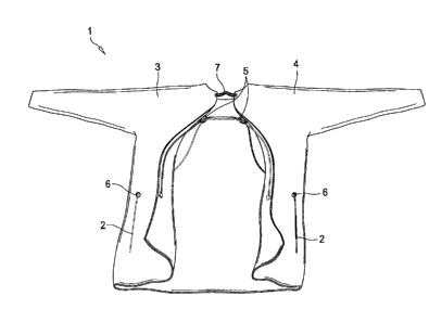
Figure 5 is the back of the gown with internal components exposed.
1

CA 02851001 2014-05-02
Figure 6 is the back of the gown when placed on the user.
Figure 7 is a side view of the gown when placed on the user.
Figure 8 is the back of a second embodiment of the gown having an opening that
starts
below the neck/head opening, with internal components exposed
DETAILED DESCRIPTION
The described embodiment shown on the figures is a gown 1 intended to be
pulled
over the user's head and rest on the user's shoulders, said gown 1 having an
opening in
the back thereof extending from the top area near the user's shoulders, to the
bottom area
of the gown. The opening may span the entire length of the gown 1 or only a
portion
thereof. One or more cords 2 are attached to the interior of the gown 1 on
each side of
the opening in the rear of the gown 1.
One end of the first cord 2 is securely attached to the interior of the gown 1
on
one side 3 of the opening in the back of the gown, at a height corresponding
to the waist
area of the user. One end of the second cord 2 is attached to the inside of
the gown 1, on
the other side 4 of the opening, also at a height corresponding to the waist
area of the
user.
A means to temporarily attach the cord to the gown in the shoulder area is
provided. The cord can be temporarily attached to the gown using a variety of
well-
known attachment methods such as a loop through which the cord is passed, hook
and
loop design, adhesives, and magnets. The choice of which method is to be used
to
2

CA 02851001 2014-05-02
temporarily attached the cord to the gown may depend on whether the gown is
disposable
or reusable.
Figure 5 shows the use of a loop 5 secured to the interior of each side of the
gown
1. The loops 5 are positioned in the top area of the gown 1, just inside the
opening. The
loop 5 may be oriented either vertically or horizontally. One or more ends of
the loop 5
are secured in such a manner that it may be easily detached from the gown 1.
As shown
in Figure 5, each cord 2 runs upwards along the inside edge of the opening on
the same
side of the gown 1 to which they originate. The cords 2 are then attached to
the gown as
described above, such as by passing through the loop 5 that is on the same
side of the
gown 1 from which that cord 2 originates.
Each cord 2 then passes through the loop 5 on the side of the gown 1 opposite
the
side from which that particular cord 2 originates. The cords 2 are then passed
through
holes 6 in the gown 1, which are positioned near the side of the gown 1 and at
the
approximate height of the waist of the user. The cords 2 are passed through
the hole 6
that is on the opposite side of the gown 1 from which that particular cord 2
originates.
In another embodiment, shown in Figure 8, the opening in the back of the gown
1
begins below the neck opening and extends the remaining length of the gown 1.
Each
cord 2 is temporarily attached to the gown 1 at only one location, just above
the opening.
For example, each cord 2 passes through one loop 5 instead of two. In this
embodiment,
one end of the first cord 2 is secured to the interior of the gown 1, on one
side 3 of the
opening, at a height corresponding to the waist area of the user. The end of
the second
cord 2 is attached to the inside of the gown 1, on the other side 4 of the
opening, also at a
height corresponding to the waist area of the user. The cords 2 run upwards
along the
3

CA 02851001 2014-05-02
inside edge of the opening on the same side of the gown 1 from which that
particular cord
2 originates. The cords 2 are passed through the single loop 5 at the top of
the gown 1.
The cords 2 are then passed through holes 6 in the gown 1, which are
positioned near the
side of the gown 1 and in the waist area of the user. The cords 2 are passed
through the
hole 6 that is on the opposite the side of the gown 1 from which they
originate.
As previously stated the gown 1 is designed to be pulled down over the head of

the user and rest on the user's shoulders. The gown 1 may be closed in the
neck area
with a hole large enough for a user's head to pass. Alternatively, the opening
in the back
of the gown 1 may span the entire length of the gown 1 with one or more
elastic/stretchable strips 7 utilized to secure two sides of the back opening
together. As
shown in figure 5, one end of the strip 7 is secured to one side 3 of the
opening in the
back of the gown with the second end of the strip 7 attached to the other side
of the
opening in the gown 1. If included, the elastic strip(s) 7 is located on the
upper portion of
the gown 1 near the neck/shoulder area, as shown in Figure 5.
The material of the gown 1 can be varied as warranted by the intended use and
the
intended user. Thus the gown 1 can be disposable or reusable. They gown 1 may
also be
made of a breathable material.
In the proposed method of use the gown 1 is placed over the head of the user
and
rests on the user's shoulders. The user pulls downwards on the cords 2,
thereby
separating the attachment cords from their temporary attachment to the gown 1.
The
cords 2 are then pulled towards the front or one side of the user until the
back of the
gown 1 is closed. The cords 2 may then be tied together in the front or side
of the gown
1.
4

CA 02851001 2016-01-12
Numerous embodiments are envisioned by this invention. I also include gowns
used in other applications besides medical such as food preparation, chemical
testing and
industrial clean rooms.
The above is a detailed description of particular embodiments of the
invention. It
is recognized that departures from the disclosed embodiments may be made
within the
scope of the invention and that obvious modifications will occur to a person
skilled in the
art. The scope of the claims should not be limited by the embodiments set
forth in the
examples, but should be given the broadest interpretation consistent with the
description
as a whole. All of the embodiments disclosed and claimed herein can be made
and
executed without undue experimentation in light of the present disclosure.

Representative Drawing
A single figure which represents the drawing illustrating the invention.
Administrative Status

For a clearer understanding of the status of the application/patent presented on this page, the site Disclaimer , as well as the definitions for Patent , Administrative Status , Maintenance Fee  and Payment History  should be consulted.

Administrative Status

Title Date
Forecasted Issue Date 2016-11-29
(22) Filed 2014-05-02
Examination Requested 2014-12-12
(41) Open to Public Inspection 2015-05-20
(45) Issued 2016-11-29

Abandonment History

There is no abandonment history.

Maintenance Fee

Last Payment of $347.00 was received on 2024-04-23


 Upcoming maintenance fee amounts

Description Date Amount
Next Payment if standard fee 2025-05-02 $347.00
Next Payment if small entity fee 2025-05-02 $125.00

Note : If the full payment has not been received on or before the date indicated, a further fee may be required which may be one of the following

  • the reinstatement fee;
  • the late payment fee; or
  • additional fee to reverse deemed expiry.

Patent fees are adjusted on the 1st of January every year. The amounts above are the current amounts if received by December 31 of the current year.
Please refer to the CIPO Patent Fees web page to see all current fee amounts.

Payment History

Fee Type Anniversary Year Due Date Amount Paid Paid Date
Application Fee $400.00 2014-05-02
Request for Examination $800.00 2014-12-12
Maintenance Fee - Application - New Act 2 2016-05-02 $100.00 2016-04-20
Final Fee $300.00 2016-10-20
Maintenance Fee - Patent - New Act 3 2017-05-02 $100.00 2017-04-24
Maintenance Fee - Patent - New Act 4 2018-05-02 $100.00 2018-04-23
Registration of a document - section 124 $100.00 2018-09-05
Maintenance Fee - Patent - New Act 5 2019-05-02 $200.00 2019-04-19
Maintenance Fee - Patent - New Act 6 2020-05-04 $200.00 2020-04-20
Maintenance Fee - Patent - New Act 7 2021-05-03 $204.00 2021-04-19
Maintenance Fee - Patent - New Act 8 2022-05-02 $203.59 2022-04-19
Maintenance Fee - Patent - New Act 9 2023-05-02 $210.51 2023-04-25
Maintenance Fee - Patent - New Act 10 2024-05-02 $347.00 2024-04-23
Owners on Record

Note: Records showing the ownership history in alphabetical order.

Current Owners on Record
GROUPE MEDICOM INC./MEDICOM GROUPE INC.
Past Owners on Record
LEVINE, IAN
Past Owners that do not appear in the "Owners on Record" listing will appear in other documentation within the application.
Documents

To view selected files, please enter reCAPTCHA code :


To view images, click a link in the Document Description column. To download the documents, select one or more checkboxes in the first column and then click the "Download Selected in PDF format (Zip Archive)" or the "Download Selected as Single PDF" button.

List of published and non-published patent-specific documents on the CPD .

If you have any difficulty accessing content, you can call the Client Service Centre at 1-866-997-1936 or send them an e-mail at CIPO Client Service Centre.


Document
Description 
Date
(yyyy-mm-dd) 
Number of pages   Size of Image (KB) 
Abstract 2014-05-02 1 13
Description 2014-05-02 5 170
Claims 2014-05-02 4 104
Drawings 2014-05-02 7 73
Representative Drawing 2015-04-22 1 8
Cover Page 2015-05-26 1 32
Claims 2016-01-12 4 104
Description 2016-01-12 5 168
Cover Page 2016-11-17 1 33
Assignment 2014-05-02 4 104
Prosecution-Amendment 2014-12-12 1 44
Prosecution-Amendment 2015-03-17 1 33
Amendment 2015-06-26 1 30
Examiner Requisition 2015-10-30 4 205
Amendment 2016-01-12 7 192
Final Fee 2016-10-20 1 43