Note: Descriptions are shown in the official language in which they were submitted.
CA 02851013 2014-04-03
WO 2012/052769
PCT/GB2011/052037
10 - I -
MUSCLE CONDITIONING / MUSCLE ASSESSMENT APPARATUS, SYSTEMS, METHODS
AND/OR COMPUTER SOFTWARE
Field of the Invention
The invention relates to muscle conditioning or muscle assessment apparatuses.
The
invention also relates to systems for muscle assessment and/or conditioning.
Optionally,
the invention relates to a method of deriving a template for muscle
conditioning or muscle
assessment. Furthermore, the invention relates to computer software configured
to
operate methods according to the invention. Optionally, the invention relates
to
apparatuses used for methods of testing and analysis. Optionally, the
invention relates to
collecting and storing values in a database.
Background to the invention
Exercise harnesses are well known in the art. However, these often present the
following
drawbacks:
* If used by untrained operators a high proportion of injuries are
likely to result;
harness straps can be misplaced, the forces applied can be disproportional,
the level
of applied force may be excessive;
e There is Mlle or no electronic feedback indicative of the level of
applied load, let
alone any scope for adjustment of the applied load; and
CA 02851013 2014-04-03
WO 2012/052769
PCT/GB2011/052037
= Prior art systems fail to provide assessments of the scientific detail
required for
improved analysis and rehabilitation programmes.
The invention seeks to overcome at least some of these drawbacks whilst
offering
a solutions to further technical problems which can be deduced from the
aspects and
description which now follow. The invention seeks to provide solutions for
muscle
conditioning or muscle assessment in both tension and compression modes.
Summary of the Invention
In a first broad independent aspect, the invention provides a muscle
conditioning or muscle
assessment apparatus comprising a load bearing component incorporating a
proximal
portion for engagement with at least part of a user's body, and a distal
portion for securing
said component to a force applying apparatus or an operator; and a transducer
located
/5 between said proximal and distal portions; said transducer being
configured to derive
signals representative of the tensile and/or compression forces applied to
said load bearing
component; wherein said apparatus further comprises means for determining one
or more
characteristics of position and/or displacement of said toad bearing
component; said
apparatus being configured to output signals representative of said force and
the direction
of said force.
In a subsidiary aspect, said toad bearing component incorporates a harness for
attachment
to at least part or a user's body, said harness incorporating one or more
straps for securing
said harness to said at least part of a user's body; a distal portion for
facilitating the
attachment of said harness to a force applying apparatus or an operator; a
transducer, one
or more joining members extending between said harness and said distal
portion.
in a second broad independent aspect, the invention provides a muscle
conditioning or
muscle assessment apparatus comprising a harness for attachment to at least
part of a
user's body, said harness incorporating one or more straps for securing said
harness to said
at least part of a user's body; a distal portion for facilitating the
attachment of said harness
to a force applying apparatus or an operator, a transducer; one or more
joining members
extending between said harness and said distal portion; wherein said
transducer is
CA 02851013 2014-04-03
WO 2012/052769
PCT/G B2011/052037
3
configured to derive signals representative of the force applied to said
joining members;
and output said signals representative of said force.
This configuration is particularly advantageous since it provides improved
determination of
the forces in the apparatus.
In a subsidiary aspect, the transducer is part of a load cell equipped with
releasable
attachment means for releasably attaching said load cell to said joining
members. This
allows the load cell to be selectively employed and/or facilitates its
replacement if
necessary.
in a further subsidiary aspect, the apparatus further comprises a wireless
transmitter for
transmitting signals to a wireless receiver located remotely from the
transmitter. This is
particularly advantageous in order to allow an operator to apply the necessary
force and to
/5 control the applied force by following indications obtained from a
wireless receiver, it also
avoids the restrictions imposed by a wire which could interfere with the
correct operation
of the apparatus.
In a further subsidiary aspect, the apparatus further comprises a housing
containing said
transducer; said housing being part metallic and part polymeric. Said
polymeric portion
being optionally in the form of a window through which wireless communication
signals
are transmitted. Said polymeric portion may also be in the form of a sleeve
for containing
at Least in part the metallic part. This is particularly advantageous in order
to protect the
sensitive electronic components contained in the housing whilst allowing
sufficient
interference-free communication to take place through the wall of the housing.
in a further subsidiary aspect, the apparatus further comprises a three-
dimensional
position sensor which determines the position of said joining members. This
allows the
processor to more rapidly determine the motion or the direction of the force
applied in
order to derive accurate values which correlate precisely to a particular
motion type.
In a further subsidiary aspect, the apparatus further comprises a gyroscope or
an angular
rate sensor for determining one or more characteristics of position and/or
displacement of
said joining members. This option is particularly advantageous in order to
apply position
CA 02851013 2014-04-03
WO 2012/052769
PCT/GB2011/052037
4
control for the apparatus or operator. This would be particularly useful in
reducing the
level of skill required by an operator.
in a further subsidiary aspect, the apparatus further comprises a position
sensor selected
from the group comprising capacitive, inductive, magnetic, and piezoelectric.
In a further subsidiary aspect, said harness incorporates a first portion
projecting, in use,
from a first side of said body part and a second portion, projecting, in use,
from a second
side of said body part; joining members being provided between said first
portion and said
ito distal portion; and between said second portion and said distal
portion; and means for
equalising tensioning forces applied on said first and second portions. This
configuration is
particularly advantageous in order to reduce the likelihood of injuries to a
subject during
his/her interaction with the apparatus.
in a further subsidiary aspect, said means for equalising tensioning forces
incorporate a
pulley. The provision of a pulley is particularly advantageous since it
involves very few
components allowing the arrangement to be advantageously lightweight and
compact.
in a further subsidiary aspect, said distal portion incorporates a handle.
This configuration
is particularly advantageous in order to allow an operator and/or a three-
dimensional
driving arm to be attached securely to the apparatus.
In a further subsidiary aspect, said transducer is provided between said
handle and said
means for equalising tensioning forces. This provides an advantageous
determination of
the tensioning forces whilst combining the advantageous equalised distribution
of forces
presented in the previous aspects.
In a further subsidiary aspect, said proximal portion incorporates a pressure
plate.
In a further subsidiary aspect, said pressure plate is concave.
In a third broad independent aspect, the invention provides a system for
muscle
assessment and/or conditioning comprising an apparatus according to any of the
preceding
aspects, a processor and a display unit located remotely from said transducer
for displaying
CA 02851013 2014-04-03
WO 2012/052769
PCT/G B2011/052037
the variation over time of the measured load for a given type of muscular
motion of a
particular muscle or muscle group. This configuration may be particularly
advantageous
when the display is in the form of a curve of the variation of load in
kilograms relative to
the lapsed time. It allows the derivation of the integral of the curve.
5
In a further subsidiary aspect, said apparatus is configured to or is employed
to steadily
increase the applied load up to the particular muscle or muscle group's
maximum. This is
particularly advantageous in order to determine the maximum values and any
endurance
level values and rehabilitation values which may be obtained from the
determination of
the maximum values,
in a further subsidiary aspect, said processor is configured to determine the
motion for
which characteristics are being measured; said motions being selected from the
group
comprising: flexion, extension, adduction, abduction, protraction, retraction
and rotation,
This further improves the interaction with a user who may have limited
knowledge of the
motion types whilst still allowing the assessment to take place.
In a further subsidiary aspect, said processor is configured to determine the
direction of the
motion; said motion being selected from the group comprising; right, left,
forwards,
backwards, upwards and downwards, This configuration is particularly
advantageous when
the apparatus is driven by a mechanical arm configured for example to drive
the various
motion types and/or load conditions,
in a further subsidiary aspect, said processor is configured to determine the
direction of the
motion in any direction in the X, Y and Z coordinate system.
In a further subsidiary aspect, said processor is configured to determine a
value
representative of the deficit between maximum flexion and corresponding
maximum
extension for a particular muscle or muscle group. This allows the
determination of areas
so which diverge from predetermined norms so that the apparatus may
determine which
corrective rehabilitation test is most appropriate.
In a further subsidiary aspect, said processor is configured to determine a
value
representative of the deficit between opposite actions,
CA 02851013 2014-04-03
WO 2012/052769
PCT/GB2011/052037
6
In a further subsidiary aspect, said processor is configured to determine a
value
representative of the deficit between contra-lateral actions.
The processor may be configured to determine a value representative of for
example
left/right biceps or for example agonist and/or antagonist.
The processor may be configured for any of unilateral/contra-lateral
testing/bilateral
testing.
In a further subsidiary aspect, said processor and said display unit are
configured to display
a template comprising a plurality of sections; each section specifying a
motion type and
having a predetermined load characteristic for a predetermined time. This
configuration is
particularly advantageous since it can act as a guide for either the apparatus
or an operator
is in order to achieve a varied rehabilitation programme.
In a further subsidiary aspect, said processor and display unit are configured
to display the
measured toad characteristic. Said measured toad characteristic being
displayed over said
template. This allows the apparatus and/or operator to apply corrective
measures if
necessary in order to achieve a particularly desired load levet.
In a fourth broad independent aspect, the invention provides a method of
deriving a
template for muscle conditioning or muscle assessment comprising the steps of:
2s * Determining the maximum load withstood for a given motion;
* Calculating a predetermined proportion of said maximum load level to
determine an
endurance load level;
* Applying a load at said determined endurance toad level up to muscular
fatigue;
* Recording the evolution of the measured load level relative to elapsed
time;
Deriving a value corresponding to the area underneath the measured load level
curve;
* Deriving a template with a plurality of sections; each section specifying
a motion type
and having a predetermined load characteristic for a predetermined time; and
CA 02851013 2014-04-03
WO 2012/052769
PCT/G B2011/052037
7
* Equating the area underneath the template to the area underneath the
measured
endurance load level curve.
This configuration provides particularly advantageous programmes for muscular
conditioning and/or rehabilitation. The derivation of the template is scalable
for a wide
variety of individuals with disparate initial conditioning and
characteristics.
in a further subsidiary aspect, the method comprises the step of selecting
said motion type
from the group comprising: isometric actions, concentric actions, eccentric
actions, hold,
:so hold left, hold right, rotate, hit central, sweep left, and sweep
right. This sequence and
potential combination of motions is particularly advantageous in order to
optimise further
the rehabilitation levels achieved by following a template of this kind.
In a further subsidiary aspect, said method incorporates a sequence of hold in
a first
direction, rotate, and hold in a second direction. This further improves the
level of
muscular conditioning and rehabilitation.
In a further subsidiary aspect, said method incorporates a sequence of rotate,
hold in a
direction and rotate.
In a further subsidiary aspect, said method incorporates a sequence of rotate,
hit central
and sweep in a first direction and a second direction,
in a further subsidiary aspect, said method incorporates a sequence of hold,
hold in a first
direction, rotate, hold in a second direction, rotate, hit central, sweep in a
first direction
and a second direction, and hold. This sequence is disproportionately
beneficial when
assessed against other sequences derived in accordance with the invention.
In a further subsidiary aspect, said template has a mean load level which is a
proportion of
a maximum test level.
in a further subsidiary aspect, said proportion is selected within the range
of 20% to 70 ,
lower than said maximum test level.
CA 02851013 2014-04-03
WO 2012/052769
PCT/GB2011/052037
8
in a further subsidiary aspect, said proportion is selected to be 75% lower
than said
maximum test levet.
in a further subsidiary aspect, said method further comprises the step of
indicating when
the recorded load evet curve area k within a predetermined percentage of a
maximum
value.
in a fifth broad independent aspect, the invention provides a computer
software
configured to operate the method of any of the appropriate preceding aspects.
in a sixth broad independent aspect, the invention provides a muscle
conditioning or
muscle assessment apparatus comprising a harness for attachment to a least
part of a
user's body, said harness incorporating one or more straps for securing said
harness to at
Least part of a users body; an attachment for facilitating the attachment of
said harness to
16 a force applying apparatus or operator; a transducer; one or more
joining members
extending between said harness and said attachment; wherein said transducer is
configured to derive a signal representative of the force applied to said
joining members;
and output a signal representative of said force; wherein said apparatus
further comprises a
processor and a display unit for displaying the variation over time of the
measured toad for
a given motion of a particular muscle or muscle group; said processor and said
display
being configured to display a template comprising a succession of distinct
sections; each
section specifying a motion type having a predetermined load characteristic
for a
predetermined time.
in a further subsidiary aspect, said processor and display unit are configured
to display the
measured load characteristic; saki measured toad characteristic being
displayed over said
template.
in a further subsidiary aspect, said template incorporates distinct sections
corresponding to
distinct rnotion types selected from the group comprising; hold, hold left,
hoid right, rotate,
hit central, sweep left, and sweep right.
In a further subsidiary aspect, said template incorporates a sequence of hold
in a first
direction, rotate, and hold in a second direction.
CA 02851013 2016-10-20
9
In a further subsidiary aspect, said template incorporates a sequence of
rotate, hold in a
direction and rotate.
In a further subsidiary aspect, said template incorporates a sequence of
rotate, hit central
and sweep in a first direction and a second direction.
In a further subsidiary aspect, said template incorporates a sequence of hold,
hold in a
first direction, rotate, hold in a second direction, rotate, hit central,
sweep in a first
/0 direction and a second direction, and hold.
In a seventh broad independent aspect, the invention provides a muscle
conditioning and
muscle assessment apparatus comprising: a load bearing component incorporating
a
proximal portion for engagement with at least part of a user's body, and a
distal portion
/5 for securing said load bearing component to a force applying apparatus
or an operator; a
transducer located between said proximal and distal portions, said transducer
being
configured to derive signals representative of at least one of tensile and
compression
forces applied to said load bearing component; and a sensor for determining at
least one
characteristic of position and displacement of said load bearing component,
said
20 apparatus being configured to output signals representative of said
force and a direction
of said force, wherein said load bearing component incorporates a harness for
attachment to at least part of the user's body, said harness incorporating: at
least one
strap for securing said harness to said at least part of the user's body; a
distal portion for
facilitating the attachment of said harness to one of the force applying
apparatus and the
25 operator; at least one joining member extending between said harness and
said distal
portion; a first portion projecting, in use, from a first side of said part of
the user's body; a
second portion projecting, in use, from a second side of said part of the
user's body;
joining members provided between said first portion and said distal portion,
and between
said second portion and said distal portion; and means for equalizing
tensioning forces
30 applied on said first and second portions.
CA 02851013 2016-10-20
9a
In an eighth broad independent aspect, the invention provides a system for
muscle
assessment and conditioning comprising: a muscle conditioning and muscle
assessment
apparatus comprising: a load bearing component incorporating a proximal
portion for
engagement with at least part of a user's body, and a distal portion for
securing said load
bearing component to one of a force applying apparatus and an operator; a
transducer
located between said proximal and distal portions, said transducer being
configured to
derive signals representative of at least one of tensile and compression
forces applied to
said load bearing component; and a sensor for determining at least one
characteristic of
position and displacement of said load bearing component, said apparatus being
configured to output signals representative of said force and a direction of
said force; and
a processor and a display unit located remotely from said transducer for
displaying a
variation over time of a measured load for a given type of muscular motion of
at least one
particular muscle.
In a ninth broad independent aspect, the invention provides a muscle
conditioning and
muscle assessment apparatus comprising: a load bearing component incorporating
a
proximal portion for engagement with at least part of a user's body, and a
distal portion
for securing said load bearing component to one of a force applying apparatus
and an
operator; a transducer located between said proximal and distal portions, said
transducer
being configured to derive signals representative of at least one of tensile
and
compression forces applied to said load bearing component; a sensor for
determining at
least one characteristic of position and displacement of said load bearing
component,
said apparatus being configured to output signals representative of said force
and a
direction of said force; and a processor and a display unit for displaying
variation over
time of a measured load for a given motion of a particular muscle, said
processor and
said display being configured to display a template comprising a succession of
distinct
sections, each section specifying a motion type and having a predetermined
load
characteristic for a predetermined time.
CA 02851013 2016-10-20
9b
Brief Description of the Figures
Figure 1 shows a plan view of an apparatus in a first embodiment of the
invention.
Figure 2 shows a side view of an apparatus according to a second embodiment of
the
invention.
Figure 3 shows block diagrams of a load cell wirelessly communicating with a
remotely
located processor and display unit
/0
Figure 4 illustrates the results of a maximum cervical test for extension and
flexion
motions.
Figure 5 shows an endurance test result.
Figure 6 shows a template in combination with the results of measured
rehabilitation
loads.
Figures 7 A and 7B show respectively side elevations of an apparatus used in
compression modes rather than tension as in the previous embodiments.
Figure 8A shows a perspective view of a pressure plate from the top.
CA 02851013 2014-04-03
WO 2012/052769
PCT/GB2011/052037
Figure 8B shows a perspective view of a pressure plate from underneath.
Figure BC shows an exploded perspective view of a pressure plate.
5
Figure 9A shows a perspective view of a further embodiment of a pressure plate
from the
top.
Figure 913 shows a perspective view of a pressure plate from beneath.
Figure 9C shows an exploded perspective view.
Figure 10A shows a perspective view of a handle.
la Figure 1013 shows an exploded perspective view of a handle.
Detailed Descrislion of the Fi7ures
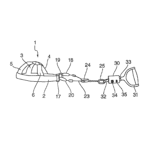
Figure 1 shows a harness 1 which may be used for exercises, conditioning,
assessments
and/or rehabilitation. The harness may take a variety of forms suitable for
attachment to
specific body parts of a subject The particular configuration of harness shown
in Figure 1
is sized and shaped to allow at least part of the head of a subject to fit
within the harness.
Harness 1 incorporates a primary band or strap 2 which is substantially C-
shaped when
viewed in plan. The strap 2 may extend in use, when fitted on the head of a
subject,
around at least part of the circumference of the subject's head. Strap 2 would
for example,
in use, be positioned above the ears of a subject and extend substantially
horizontally or at
eye level. Projecting inwardly from the strap 2, there are provided a
plurality of
substantially radially extending secondary straps 3, 4, 5 and 6. Each
individual said strap
may be pivotally attached to primary strap 2. Straps 3, 4, 5 and 6 are
provided to extend
across the upper part of the subject's cranium. At their distal extremities,
such as
extremity 7, each strap employs a tunnel through which a rope, string or strap
8 is
threaded. The extremities 9 and 10 of the attaching string are held together
by a clasp or
bead 11. Bead 1 1 may frictionally grip or clamp on to the strings which are
held in the
bead. A further form of strap is provided as strap 12 and is sized and
configured to act as a
CA 02851013 2014-04-03
WO 2012/052769 PCT/GB2011/052037
it
chin strap. At its extremities the chin strap 12 may also be pivotally mounted
to the
primary strap 2. A rivet 13 or like attachment means may be provided in order
to achieve
the necessary relative rotation.
The various straps of the harness may be equipped with releasable attachment
means
between interconnected portions of straps. These may take the form of press-
stud
fasteners. These may also take the form of filamentary touch-to-close systems
which are
often referred to as VELCRO fasteners (VELCRO is a registered trade mark). The
releasable
attachment may preferably have an audible release in order to warn of a
particular hazard.
A number of linkage members generally referenced 14 are provided between the
harness
and a toad cell (not shown in Figure 1). At opposite extremities 15 and 16 of
strap 2, rings
17 and 19 are respectively secured to karabiners 18 and 20. Karabiners 18 and
20 are also
secured to loops 21 and 22 which are provided at opposite extremities of cable
23. Cable
23 is thread through pulley housing 24 and is sized and shaped to fit within
the peripheral
track of the pulley (not shown). in order to avoid undue twisting of the
joining members, a
universal joint or ball joint 25 is mounted onto the distal extremity of the
pulley housing.
The universal joint may have facilitate rotation relative to two axis of
rotation disposed at
right angles. One of these axes may be substantially longitudinal whilst the
other may be
normal to the longitudinal direction. A further karabiner 26 links the
universal joint to a
loop 27 which joins oppositely disposed chains 28 and 29.
Optionally, at least cable 23, straps 2-6 are substantially non-elastic.
Whilst a pulley 24 has been illustrated as a particularly advantageous form of
means for
equalising tensioning forces, other systems may be employed. These may include
for
example a clamp based system or a hydraulically controlled load distributor,
Figure 1 is configured to allow the attachment of a load cell which determines
the tension
in the linkage members. Figure 2 shows a harness, joining members, a load cell
and a
handle. The components of the apparatus of Figure 2 which are common with the
components of the apparatus of Figure 1 have retained identical numerical
references for
clarity. Universal joint 25 is preferably directly attached to a load cell 30
which in turn is
CA 02851013 2014-04-03
WO 2012/052769
PCT/GB2011/052037
2
preferably directly attached to a handle 31. The attachment between load cell
30 and
universal joint 25 incorporates a fastener 32 which may be a threaded
projection which
releasably engages with a threaded recess in the load cell 30. Similarly, a
fastener 33 is
provided between the load cell 30 and the handle 31 which may be released by
an
operator by releasing a nut or other suitable releasable fastener.
The load cell 30 incorporates a housing which is cylindrical and may be
circular in cross
section, The housing may primarily be formed of aluminium or stainless steel
with the
circuitry or sensor being fully enclosed within the housing. in order to mount
the internal
id components of the load cell, a first openable window 34 may be provided.
Furthermore,
the housing may be provided with a second window to allow transmission of
communication signals through the housing. This second window may be made of a
suitable polymer. An on/off switch may be provided on either of the end faces
of the
cylindrical housing, Furthermore, a socket may be provided to engage a power
cable for
charging batteries or for powering the electrical components contained within
housing 30.
Figure 3 shows the primary components of the load cell in further detail. in
particular, the
load cell may include a load sensor which may take the form of a transducer
which
generates signals which are representative of the force applied across the
toad cell. The
load sensor may incorporate a strain gauge which causes a change in voltage
dependent
upon the extent to which the strain gauge is stretched. The load sensor may
alternatively
be any one of the sensors selected from the group comprising angular rate,
capacitive,
inductive, magnetic, and piezoelectric. For example, by providing a
piezoelectric unit which
when stretched generates a variable voltage and/or current, a signal
representative of the
load applied on the toad cell is obtained and consequently a signal
representative of the
tensile forces in the linkage members of the apparatus described in Figures 1
and 2 may be
derived.
In order for the apparatus illustrated in Figures 1 and 2 to have its maximum
effect
determining the position in space of the load sensor is particularly
advantageous. In order
to do so, a position sensor in addition to the load sensor may be provided as
part of the
circuitry located within the load cell. In order to detect changes in the
angular position of
the load cell, it is particularly advantageous to incorporate an electronic
angular rate
sensor or gyroscope. Instead and/or in addition to an electronic gyroscope,
the
CA 02851013 2014-04-03
WO 2012/052769
PCT/GB2011/052037
13
embodiment also envisages the position sensors selected from the group
comprising
capacitive, inductive, magnetic, and piezoelectric.
A transmitter is also envisaged in order to allow wireless communication
between the load
cell and a remotely positioned processing unit. By combining the muscle
conditioning or
muscle assessment apparatus of Figures 1 and 2 with the processing and
displaying unit, a
system for muscle assessment and/or conditioning is provided, Whilst Figure 3
illustrates
that the processor is provided as part of the receiver unit, it is also
alternatively envisaged
to provide the processor within the load cell or as part of a third distinct
unit if necessary.
As illustrated in Figure 3, the transmitter of the load cell is configured to
transmit to a
receiver in the receiving unit. However, both the load cell and the receiver
unit may
incorporate transmission and receiving capabilities. The load cell may for
example be
equipped with a receiver to facilitate the calibration of the sensors. The
receiver unit
would also optionally incorporate a power source, an on/off switch and a user
interface.
The user interface may be in the form of a touch screen which may both display
data and
allow the operator to select from a range of options.
Figure 4 shows the potential results of measurements measured in the load cell
30 of
Figure 2, transmitted to the processor for display on a screen in a co-
ordinate system with
the load values provided in the Y-axis and the time in seconds provided in the
X-axis. In
this embodiment, a user's head was placed in the harness 'I and the harness
was oriented
in a first mode of motion corresponding to cervical flexion and in a second
mode of
motion corresponding to cervical extension. As shown in the measurements, the
load
steadily increases in almost linear fashion up to the maximum, at which point
the toad
decreases rapidly. This Figure illustrates the variation over time of the
measured load for a
given type of muscular motion (flexion or extension) of a particular muscle or
muscle
group (the cervical group),
In this illustration, the maximum flexion load determined was F(max)=33.4
whilst the
maximum extension value determined was Ex(max).79.2.
These measured values allow the derivation of a flexion/extension deficit by
following the
formula:
CA 02851013 2014-04-03
WO 2012/052769
PCT/GB2011/052037
14
Flexion/extension deficit = (1-(F(max)/Ex(max))) x 100
For example : Flexion/extension deficit = (1-(33e11792)) x 100 = 57%
The same bask formula may be followed to determine side flexion left and side
flexion
right. Once the maximum side flexion left and side flexion right values are
determined, the
side flexion deficit may also be derived.
In addition to the cervical test for flexion and extension further similar
tests may be carried
out by employing the harness configuration of Figure 2. In particular, a
cervical rotation
test may be employed to determine the various maxima for distinct motions such
as
flexion left rotation, flexion right rotation, extension left rotation,
extension right rotation.
As detailed with respect to the cervical test, the cervical rotation test
altows the deficit
between flexion left rotation and flexion right rotation to be determined.
Furthermore, the
deficit between extension left rotation and extension right rotation may also
be
determined.
Further tests may be conducted, for example a shoulder test, an elbow test, a
wrist test
may also be carried out by appropriately strapping the harness of Figure 2
around the
appropriate body part to carry out the various motions,
This method allows a comprehensive and detailed assessment of particular
motions of
muscles and/or muscle groups,
The term "motion" is to be interpreted as including amongst others, flexion,
extension,
adduction, abduction, and rotation.
For the shoulder test, the motions taken into consideration include at least
the following:
flexion left, flexion right, extension left, extension right.
For the shoulder rotation test, the following motions may be taken into
consideration:
internal rotation left, internal rotation right, external rotation left, and
external rotation
right.
CA 02851013 2014-04-03
WO 2012/052769
PCT/G B2011/052037
For the shoulder abduction test, the various motions taken into consideration
include at
least: abduction (first position) left, abduction (first position) right,
abduction (second
position) left and abduction (second position) right.
6
For the shoulder adduction test, the following motions may be taken into
consideration:
adduction (first position) left, adduction (first position) right, adduction
(second position)
left, and adduction (second position) right.
io For the shoulder test of the scapular retraction/shrug, the following
motions at least may
be taken into consideration: scapular retraction left, scapular retraction
right, shrug left,
and shrug right.
For the elbow test, the following motions may be taken into consideration:
flexion (first
is position) left flexion (first position) right, flexion (second position)
left, and flexion (second
position) right.
For the elbow test of extension/wrist grip, the following motions at least may
be taken
into consideration: extension left and extension right.
As a further example, the motions taken into account in the wrist
flexure/extension test
may be the following: flexion left, flexion right, extension left, and
extension right.
A further example may be obtained from a thumb extension/fifth digit (little
finger)
abduction test by taking into account the following motions: thumb extension
left, thumb
extension right, fifth abduction left, and fifth abduction right.
The following embodiment illustrates the method of deriving a template for
muscle
conditioning or muscle assessment. As illustrated in the previous embodiment
the
maximum extension endurance determined was approximately 80kg for cervical
extension.
Once this value has been determined by the apparatus, the processor may be
configured
to calculate a predetermined proportion of the maximum load level to determine
a fatigue
toad Level, The fatigue load level may be set for example at 50% of the load
reached in the
maximum test of Figure 4.
CA 02851013 2014-04-03
WO 2012/052769
PCT/GB2011/052037
16
The thick horizontal line in Figure 5 illustrates the 50% level for performing
an extension
fatigue test. The apparatus or operator applies a load at said determined
fatigue load level
up to muscular release, The curve in Figure 5 shows the measured load obtained
from the
measurements of the load cell, After approximately 80 seconds the user reaches
the
fatigue point and the load consequently drops off. By calculating the integral
of the curve
shown in Figure 5, the area beneath the curve can be determined. This may for
example
be approximately 2,700kg. Instead of simply repeating this fatigue test, a
template for a
rehabilitation programme is derived by the processor. The template is formed
from a
plurality of sections or successive sections; each section specifying a motion
type and
having a predetermined load characteristic for a predetermined time. The area
beneath
the thickened line in Figure 6 corresponds to the area calculated by
integrating the
measured curve in Figure 5. The apparatus thereafter applies a Load and a
motion
corresponding to the various sections of the template in order to carry out a
rehabilitation
programme. The curve shown in close proximity to the various sections of the
template
corresponds to the measurements derived from the load cell as the apparatus or
the
operator applies the necessary force in the specified template directions.
The template is formed from a plurality of sections selected from the group
comprising:
hold, hold left, hold right, rotate, hit central, sweep left, and sweep right.
The various motions as employed in the template of Figure 6 are as follows:
6 A = hold;
0 B = hold left;
= C = rotate;
* D = hold right;
= E = rotate;
* F = hit central;
= G = sweep left/right;
* H = hold;
= = hold;
* I = max out,
CA 02851013 2014-04-03
WO 2012/052769
PCT/GB2011/052037
17
Figure 7A shows a muscle conditioning or muscle assessment apparatus generally
referenced 36. As in the previous embodiments, the apparatus incorporates a
load-bearing
component. However, instead of it being a harness, it is a relatively rigid
structure in order
to apply compression on a user. The load-bearing component incorporates a
handle 37 at
a distal portion for securing the component to a force applying apparatus or
to the hand of
the operator. The handle is C-shaped in side view with a primary hand engaging
axle 38
located between extremities 39 and 40 of the C-shaped member. A releasable
attachment
41 is provided between the handle and a load cell housing 42. As in previous
embodiments, a number of apertures 43 and 44 are provided to either allow
access to the
housing and/or to allow connectivity and/or transmission with separate
processing means.
A further releasable attachment means 45 is provided at the proximal extremity
of the
Load-bearing component. This releasable attachment means secures a pressure
plate 46 to
the load cell housing. The pressure plate may be generally flat in some
embodiments.
However, as shown in Figure 7A it may be substantially C-shaped in cross
section. it may
be substantially concave and/or convex dependent upon the area of the body
against
which, in use, the pressure plate would be placed.
The apparatus of Figure 7B is identical to the embodiment of Figure 7A apart
from the
configuration of pressure plate 47. This configuration of pressure plate
incorporates a
block with a front recess 48 sized and shaped to engage against a particular
member of the
user's body.
Figures 8 and 9 provide further detail of the embodiments of Figures 7A and
78. Figure 8A
shows a pressure plate 49 with a front concave surface 50. An array of pimples
51 projects
from the surface 50. The array is placed primarily about the middle portion of
the pressure
plate rather than extending across its entire width. Extending rearward from
the pressure
plate, a boss 52 is provided. As shown in Figure 8C, boss 52 is secured onto
bar 53 by a
fastener 54. Bar 53 is covered by a moulding 54 which may be etastomeric. A
stud 55
may be employed to secure boss 52 to the load cell (not shown in the Figure).
Figure 9 shows a pressure plate arrangement 56 with a circular recessed
portion 57 with a
forward-most surface 58. Surface 58 exhibits an array of pimples 59. The
pressure plate is
formed from a fiat bar 60 over which is secured an elastomeric moulding 61.
The
CA 02851013 2014-04-03
WO 2012/052769
PCT/GB2011/052037
18
elastomeric moulding incorporates a rear recess 62 in order to allow plate 60
to be tightly
secured. A screw 63 fastens plate 60 on to boss 64. Stud 65 is provided to
join boss 64 to
a load cell.
Figure 10A shows a handle 66 formed by a C-shaped plate 67 and an axle 68. A
fastener
69 secures boss 70 onto the distal side of the plate 67. Boss 70 is in turn
secured to stud
71 for attachment to the toad cell. Axle 68 is formed by an outside cover 73,
which may
be of elastomeric material in order to be placed over a solid bar 72. The bar
is secured at
opposite ends to the C-shaped plate by fasteners 74 and 75.
As previously described, the load cell and/or the Load bearing component of
the apparatus
may be equipped with a position sensor. This would allow the direction of the
loading to
be optimised. For example, in the context of the compression apparatus of
Figures 7-10
this would for example allow compression to be applied at right angles to the
body
member against which the pressure plates are located. Similarly, it would
allow the
harness as the load bearing component in preceding embodiments to be applied
at the
prescribed angle in addition to the load being applied at a predetermined
level