Note: Descriptions are shown in the official language in which they were submitted.
CA 02851073 2014-05-02
EXHAUST MIXER WITH OFFSET LOBES
TECHNICAL FIELD
The application relates generally to aircraft gas turbine engines and, more
particularly,
to gas turbine engine exhaust mixers.
BACKGROUND OF THE ART
In turbofan engines, high velocity air from the turbofan core is mixed with
low velocity
air from the bypass duct, and this mixed air is then exhausted from the
engine.
Turbofan engines generally use exhaust mixers in order to increase the mixing
of the
high and low velocity fluid flows. Various different configurations of exhaust
mixers have
been used in order to increase the mixing of the fluid flows.
Generally, the flow exiting the last turbine stage has significant swirl and
is de-swirled
by a set of de-swirling struts upstream of the mixer. At the exit of these
struts there is
residual swirl. Generally a straight mixer further straightens the flow at a
cost of
pressure losses and directs the flow so that it is essentially axial at the
exit of the mixer.
Some exhaust mixer configurations have also been proposed to further reduce
the swirl
of the engine when compared to a straight mixer, for example by providing
inner lobes
curved in a direction opposite to that of the swirl.
SUMMARY
In one aspect, there is provided an exhaust mixer for a gas turbine engine of
the type
having an annular bypass passage for channelling air from a fan flow and a
main gas
path passage, the exhaust mixer being adapted to receive a flow from the main
gas
path passage having a swirl component in a given direction, the exhaust mixer
comprising: an annular wall defining a central longitudinal axis, the annular
wall having
opposed upstream and downstream ends and defining a plurality of
circumferentially
distributed alternating inner and outer lobes, with each inner lobe protruding
into the
main gas path passage, and each outer lobe protruding into the annular bypass
passage, each outer lobe having a crest line extending substantially
longitudinally
through each radially outermost point of the outer lobe and a base defined
between
spaced apart wall portions of the outer lobe at an upstream end of the crest
line, at
1
CA 02851073 2014-05-02
least a downstream portion of the crest line being curved with respect to a
circumferential direction of the mixer and defining at the downstream end a
circumferential offset with respect to the base in a direction corresponding
to that of the
swirl component.
In another aspect, there is provided an exhaust mixer for a gas turbine engine
of the
type having an annular bypass passage for channelling air from a fan flow and
a main
gas path passage, the exhaust mixer being adapted to receive a flow from the
main gas
path passage having a swirl component in a given direction, the exhaust mixer
comprising: an annular wall defining a central longitudinal axis, the annular
wall defining
a plurality of circumferentially distributed alternating inner and outer
lobes, with each
inner lobe protruding into the main gas path passage, and each outer lobe
protruding
into the annular bypass passage, and each outer lobe defines in a cross-
section
located at a downstream end thereof a center line extending at equal distance
from
spaced apart portions of the wall defining the outer lobe, the center line
extending at a
non-zero angle with respect to a radial line extending from the central
longitudinal axis
and intersecting the center line at a tip of the outer lobe, the center line
being oriented
to define a circumferential offset of the outer lobe at the downstream end
relative to an
upstream end thereof in a direction corresponding to that of the swirl
component.
In a further aspect, there is provided a method of mixing a core flow and a
bypass flow
surrounding the core flow with an annular mixer having circumferentially
alternating
inner and outer lobes, the method comprising: circulating the core flow
through the
mixer and the bypass flow around the mixer; generating pairs of counter
rotating radial
vortices within the core flow near a tip of the outer lobes; and with the
outer lobes,
guiding a downstream transport of the vortices such that adjacent ones of the
vortices
in a same pair move along different paths defined at different radial
distances from a
longitudinal axis of the mixer.
DESCRIPTION OF THE DRAWINGS
Reference is now made to the accompanying figures in which:
Fig. 1 is a schematic cross-sectional view of a gas turbine engine;
2
CA 02851073 2014-05-02
Fig. 2 is a tridimensional view of a mixer in accordance with a particular
embodiment,
which can be used in a gas turbine engine such as shown in Fig. 1;
Fig. 3 is a rear view of the mixer of Fig. 2;
Fig. 4 is a top tridimensional view of part of the mixer of Fig. 2;
Fig. 5 shows in superposition three cross-sections of a same outer lobe within
different
planes defined along the length of the mixer of Fig. 2;
Fig. 6 is a side, rear perspective view of part of the mixer of Fig. 2;
Fig. 7 is a top tridimensional view of part of a mixer in accordance with
another
particular embodiment;
Fig. 8 is a side, rear perspective view of part of a mixer in accordance with
another
particular embodiment;
Fig. 9A is a tridimensional schematic representations of vortices in an outer
lobe of a
straight mixer; and
Fig. 9B is a tridimensional schematic representation of vortices in an outer
lobe of a
mixer according to a particular embodiment.
DETAILED DESCRIPTION
Fig.1 illustrates a gas turbine engine 10 of a type preferably provided for
use in
subsonic flight, generally comprising in serial flow communication a fan 12
through
which ambient air is propelled, a compressor section 14 for pressurizing the
air, a
combustor 16 in which the compressed air is mixed with fuel and ignited for
generating
an annular stream of hot combustion gases, and a turbine section 18 for
extracting
energy from the combustion gases.
The gas turbine engine 10 includes a first casing 20 which encloses the turbo
machinery of the engine, and a second, outer casing 22 extending outwardly of
the first
casing 20 such as to define an annular bypass passage 24 therebetween. The air
propelled by the fan 12 is split into a first portion which flows around the
first casing 20
within the bypass passage 24, and a second portion which flows through a main
gas
path 26 which is defined within the first casing 20 and allows the flow to
circulate
3
CA 02851073 2014-05-02
through the multistage compressor 14, combustor 16 and turbine section 18 as
described above.
At the aft end of the engine 10, an axisymmetrical bullet 28 is centered on a
longitudinal
axis 30 of the engine 10 and defines an inner wall of the main gas path 26 so
that the
turbine exhaust gases flow therearound. An annular mixer 32 surrounds at least
a
portion of the bullet 28, the mixer 32 acting as a rearmost portion of the
outer wall
defining the main gas path 26 and a rearmost portion of the inner wall
defining the
bypass passage 24. The hot gases from the main gas path 26 and the cooler air
from
the bypass passage 24 are thus mixed together by the mixer 32 at the exit
thereof such
as to produce an exhaust with a reduced temperature.
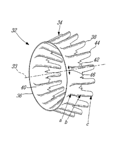
Referring to Figs. 2-3, the mixer 32 has a central longitudinal axis 33 and
includes an
annular wall 34 defining an upstream end 36 of the mixer 32 along which the
flows from
the main gas path 26 and from the bypass passage 24 are received, and a
downstream
end 38 where the two flows meet and are mixed together. The annular wall 34
includes
a frustoconical portion 40 extending from and defining the upstream end 36,
the
frustoconical portion 40 having a diameter progressively reducing toward the
downstream end 38. The annular wall 34 also defines a plurality of
circumferentially
distributed lobes extending rearwardly from the frustoconical portion 40. The
lobes
include alternating inner and outer lobes 42, 44, with the outer lobes 44
extending into
the bypass passage 24 and the inner lobes 42 extending into the main gas path
26. As
such, the inner lobes 42 define troughs in the bypass passage 24 in between
adjacent
ones of the outer lobes 44, while the outer lobes 44 define troughs in the
main gas path
26 in between adjacent ones of the inner lobes 42. In the embodiment shown,
each
lobe 42, 44 has a radially elongated cross-section including a rounded tip 47,
and
extends from the frustoconical portion 40 to the downstream end 38 of the
mixer 32.
The present mixer 32 is configured to allow (e.g. maintain or increase) the
swirl in the
turbine exhaust flow for enhanced mixing. In a particular embodiment, the
mixer 32
allows for improved aerodynamic performance relative to a straight mixer
design.
Referring to Fig. 4, each inner lobe 42 defines an imaginary valley line 43
extending
substantially longitudinally through its radially innermost points. Each outer
lobe 44
defines an imaginary crest line 45 extending longitudinally or substantially
longitudinally
4
CA 02851073 2014-05-02
through its radially outermost points. In a typical straight mixer, each crest
line and
each valley line extends longitudinally. In the embodiment shown in Fig. 4,
the crest
lines 45 and, optionally, the valley lines 43 are curved with respect to a
circumferential
direction of the mixer 32; in other words, the crest lines 45 and, optionally,
the valley
lines 43, have a curved shape when viewed in a respective direction which in a
conventional straight mixer would superpose the crest line 45/valley line 43
with the
longitudinal axis 33. The crest lines 45 are curved such as to define a
circumferential
offset with respect to the longitudinal axis 33 in the same direction as that
of the swirl,
as will be detailed further below.
In a particular embodiment, the path of the curved crest lines 45 and valley
lines 43 are
obtained from a straight mixer configuration through circumferentially
twisting the crest
lines 45 and valley lines 43 about the longitudinal axis 33. The
circumferential twist of
the crest lines 45 may be the same or different from that of the valley lines
43. In
another embodiment, the path of the curved crest lines 45 is obtained from a
straight
mixer configuration through pivoting of each crest line 45 about a respective
pivot point
located on a circle extending through the valley lines 43. Alternately, any
other type of
curvature that deflects the crest lines 45 and optionally, the valley lines 43
in the
circumferential direction may be used. The valley lines 43 may be deflected in
the same
or in an opposite direction as that of the crest lines 45.
The crest lines 45 and, optionally, the valley lines 43 may be deflected at a
constant
rate along the longitudinal direction of the mixer 32, or alternately, the
rate of deflection
may vary along the longitudinal direction.
The crest lines 45 and, optionally, the valley lines 43 can be deflected along
only a
downstream portion thereof, such that the outer lobes 44 and, optionally, the
inner
lobes 42 extend straight from the upstream end 36 up to location intermediate
the
upstream and downstream ends 36, 38 and then are circumferentially deflected
between that location and the downstream end 38. In another embodiment, the
crest
lines 45 and, optionally, the valley lines 43 are deflected along their entire
length.
Referring to Fig. 5, three (3) cross-sections of a same outer lobe 44 are
shown, with
each cross-section being located in a respective plane extending
perpendicularly to the
longitudinal axis 33, at the locations a, b, c shown in Fig. 2. Cross section
44c is located
5
CA 02851073 2014-05-02
in a plane at the downstream end 38 of the mixer 32, cross-section 44a is
located in a
plane closer to the upstream end 36, and cross-section 44b is located in a
plane
between that of cross-sections 44a and 44c. Each outer lobe 44 includes a base
46
which is defined adjacent the frustoconical portion 40, at the upstream end of
the crest
line 45.
At the downstream end 38 of the mixer 32, illustrated by cross-section 44c,
the crest
line 45 of each outer lobe 44 is circumferentially offset with respect to the
base 46. It
can be seen that an imaginary radial tip line Tc extending from the central
longitudinal
axis 33 to the crest line 45 is circumferentially offset from an imaginary
radial base line
B extending from the central longitudinal axis 33 to a midpoint of the base
46. The
direction of the circumferential offset Oc from the base line B to the tip
line Tc
corresponds to the direction of the swirl S of the turbine exhaust flow
entering the mixer
32. In a particular embodiment, the offset angle Oc at the downstream end 38
is at
most 5 . In a particular embodiment, the offset angle Oc at the downstream end
38 is at
most 2 . In a particular embodiment, the offset angle Oc at the downstream end
38 end
is at least 0.5 .
In the embodiment shown, the circumferential offset of the outer lobes 44
becomes
progressively more pronounced toward the downstream end 38 of the mixer 32.
Accordingly, the offset angle Oa from the radial base line B to the radial tip
line Ta of
the cross-section 44a closest to the upstream end 36 is smaller than the
offset angle
Ob from the radial base line B to the radial tip line Tb of the intermediary
cross-section
44b, which is smaller than the offset angle Oc at the downstream end 38.
In the embodiment shown and with reference to Fig. 2, each outer lobe 44 in
cross-
section defines an imaginary center line extending at equal distance from the
wall
portions defining the outer lobe 44, illustrated at C for the downstream end
38 in Fig. 2.
In the embodiment shown, it can be seen that the center line C at the
downstream end
38 is angled (i.e. extends at a non-zero angle) with respect to an imaginary
radial line R
extending from the longitudinal axis 33 and intersecting the center line C at
the center
of the tip 47; the outer lobe 44 is thus tilted with respect to the radial
direction R. In the
embodiment shown, each outer lobe 44 has a straight center line C and is
symmetrical
with respect thereto. Alternately, the center line C and wall portions forming
the outer
6
CA 02851073 2014-05-02
lobes 44 may be curved and/or the outer lobe 44 may be asymmetrical about the
center
line C.
Referring to Fig. 6, in a particular embodiment, the trailing edge junction of
each outer
lobe 44 with the adjacent inner lobes 42 defines a scallop 48, from which
extends a
pointed tab 50. In another particular embodiment shown in Fig. 8, the trailing
edge
junction of each outer lobe 44 with the adjacent inner lobes 42 defines only a
scallop
148. Any other adequate trailing edge treatment may alternately be used, for
example a
tabbed trailing edge.
Fig. 7 shows an alternate embodiment for the mixer 132 where the crest lines
145 are
curved relative to the longitudinal direction and where the valley lines 143
are straight.
In a particular embodiment, the valley lines 143 are coplanar with the
longitudinal axis,
such that the inner lobes 42 are straight and longitudinal. In a particular
embodiment,
the path of the curved crest lines 145 is obtained through pivoting of each
crest line 145
about a respective pivot point located on a circle extending through the
valley lines 143.
In use, the turning of the outer lobe 44 through circumferential deflection of
the crest
line 45, 145 changes the trajectory of the crest vortex pair such that the
centres of the
vortices are at different radii. Referring to Fig. 9A, in a conventional mixer
with straight
longitudinal lobes, the mixing is achieved through radial vortices generated
in the shear
layer and pairs of counter rotating vortices generated by the core flow
penetrating into
the cold flow at the lobe crest and that are transported downstream
symmetrically or
substantially symmetrically (a small amount of residual swirl may prevent the
flow from
being exactly symmetrical). The centers 60, 60' of the pair of vortices are
transported
downstream symmetrically along a path 62 located at a same radial distance
from the
longitudinal axis 33.
In a particular embodiment, and referring to Fig. 96, the offset of the outer
lobes 44
changes the trajectory of the pairs of vortices such that the centers of
adjacent vortices
160, 160' migrate to paths 162 defined at different radii. Because of the
shift in radii,
the span of radius over which the vortices have an effect is increased,
increasing
mixing. In addition, the two adjacent vortices of consecutive lobes are also
at different
radii which increase their interaction resulting in more cold flow between
consecutive
lobes being involved in the mixing process. Finally, the interactions of the
vortices with
7
CA 02851073 2014-05-02
the shear layer formed by the mixer side walls result in the shear layer
deforming and
increasing its surface area, further increasing the mixing area.
Generally, turning the flow is known to increase pressure losses due to the
resulting
secondary flows generated. In a particular embodiment, the configuration
offset outer
lobes 44 (and optionally, offset inner lobes 42) result in an increase in the
mixing
downstream of the mixer 32, 132 without or with a limited increase in pressure
loss.
This may provide an increase in thrust coefficient over a straight mixer at
the same
engine condition, resulting in a reduction in specific fuel consumption.
In a particular embodiment and as mentioned above, the minimum turn or offset
angle
to turn the flow sufficiently to cause the radial migration is 0.5 . In a
particular
embodiment, the upper limit for the offset angle is determined such as to
limit the
pressure losses. In a particular embodiment, the maximum offset angle is 2 .
In another
particular embodiment, the maximum offset angle is 5 . An offset angle that is
too high
may lead to an increase in tossed in the mixer and nozzle high enough to
reduce the
resulting thrust coefficient, which may cause an increase in specific fuel
consumption
instead of the desired reduction. Losses in the mixer and nozzle may include
bypass
loss (loss incurred from the outer lobe leading edge to the mixer trailing
edge), core
loss (loss incurred from the inner lobe leading edge to the mixer trailing
edge) and/or
mixing pressure loss (loss incurred from the mixer trailing edge to the nozzle
exit).
In a particular embodiment, the improved mixing of the mixer 32, 132 is
achieved by
increasing the area of the shear layer between the core and bypass streams
over which
the two flows can mix, as compared with a straight mixer at the same engine
condition.
In a particular embodiment, the improved mixing is achieved by adding a
rotational
component to the flow downstream of the mixer 32, 132 that causes additional
interaction of the vortices generated by the mixer 32, 132.
In a particular embodiment, the mixer 32, 132 enhances the interaction of a
low level of
residual swirl in the core and bypass flow with the mixing flow structures,
which results
in residual swirl increasing performance. This is contrary to a straight mixer
for which
residual swirl is generally a performance penalty. In a particular embodiment,
the mixer
32, 132 allows for a higher allowable residual swirl with the benefit that the
amount of
deswirling required downstream of the low pressure turbine is reduced,
lowering the
8
CA 02851073 2014-05-02
loss of the turbine exhaust case. De-swirling TEC struts 19 (see Fig. 1)
leaving some
residual swirl may thus be used upstream of the mixer 32, 132.
A limiting factor of mixer design may be avoidance of hot gas impingement on a
nozzle
wall 21 (see Fig. 1) downstream of the mixer, as nozzles are often made from
composite material with temperature capabilities below the temperature of the
hot gas.
The degree of impingement is a function of the degree of penetration of the
outer lobes
into the cold flow. In a conventional straight mixer, the area of mixing may
be increased
by increasing penetration, but the hot gas impingement on the nozzle wall
limits the
possible increase in penetration and as such the possible performance
improvement. In
a particular embodiment, the offset outer lobes 44 of the mixer 32, 132 allow
for an
increased area of the shear layer of mixing when compared to a straight mixer
having
the same penetration, thus allowing a higher level of mixing to be achieved
without
impinging on the downstream nozzle. The mixer 32, 132 may be used in
combination
with a straight or canted nozzle, i.e. nozzle having an exit centerline not in
line with the
longitudinal axis 33.
The above description is meant to be exemplary only, and one skilled in the
art will
recognize that changes may be made to the embodiments described without
departing
from the scope of the invention disclosed. Modifications which fall within the
scope of
the present invention will be apparent to those skilled in the art, in light
of a review of
this disclosure, and such modifications are intended to fall within the
appended claims.
9