Note: Descriptions are shown in the official language in which they were submitted.
CA 02851154 2014-04-03
WO 2013/052863
PCT/US2012/059052
1
TITLE
IMAGE-BASED ANIMAL CONTROL SYSTEMS AND METHODS
CROSS-REFERENCE TO RELATED APPLICATIONS
[0001] This application claims the benefit of U.S. Provisional Patent
Application No. 61/543,534, filed on October 5, 2011.
FIELD OF INVENTION
[0002] The present general inventive concept relates to systems and
methods
of controlling animals and associated objects, and more particularly, to image-
based tracking systems and methods capable of controlling animals and/or other
objects based on visual and/or audible activity occurring within a field of
view of
one or more cameras.
BACKGROUND
[0003] It is often desirable to contain animals within a given
boundary, and
to identify when an animal has left such a boundary. Conventional electronic
animal containment systems typically employ a buried wire to define a
containment
barrier. The wire radiates a signal that is sensed by a device worn by a
monitored
animal. As the monitored animal approaches the perimeter, the signal is sensed
and the device delivers a stimulus to the animal to dissuade it from breaching
the
perimeter.
[0004] Global positioning systems (GPS) have also been used to define
the
boundaries of a selected containment area. In such systems, the position of
the
animal(s) to be confined is monitored through the use of GPS satellites to
determine
if and when the animal crosses a boundary. Typically, a portable programming
transceiver is used to program the boundary of a selected confinement area as
the
device is moved along such boundary. A programmable collar transceiver worn by
the animal provides GPS signals from the satellite to a remotely located
control
station. The control station tracks the movement of the animal relative to the
boundary. If the animal crosses the boundary, the station transmits a stimulus
CA 02851154 2014-04-03
WO 2013/052863
PCT/US2012/059052
2
activation signal to the collar so that a corrective stimulus may be produced
for the
animal. Tracking and containment of objects are accomplished by providing GPS-
defined, user-programmable containment areas
BRIEF SUMMARY
[0005] The present general inventive concept provides a camera-based
tracking system to track the location of objects, such as dogs or other
animals
relative to a virtual border defined within a field of view of one or more
cameras. As
used herein, the term "camera" is meant to include various types of image
capturing devices, including CCD or CMOS cameras, infrared detectors, laser
detectors, semiconductor detectors, scanning devices, or other known or later
developed image sensing devices.
[0006] In some embodiments, the present general inventive concept
provides
a camera-based tracking system capable of controlling animals and/or other
objects based on visual and/or audible activity occurring within a field of
view of
one or more cameras.
[0007] Additional features and embodiments of the present general
inventive
concept will be set forth in part in the description which follows and, in
part, will be
obvious from the description, or may be learned by practice of the present
general
inventive concept.
[0008] Example embodiments of the present general inventive concept can be
achieved by providing a pet containment system, including a camera system to
visualize a location of an animal within a field of view of the camera, a
controller to
define a border within the field of view and to compare the location of the
animal
relative to the defined border, and a transmitter to transmit a stimulation
signal to
the animal to dissuade the animal from crossing the border based on the
comparison.
[0009] Example embodiments of the present general inventive concept
can
also be achieved by providing an animal tracking system including a camera
system to visualize a location of an animal within a field of view of the
camera, a
controller to define a border within the field of view and to compare the
location of
CA 02851154 2014-04-03
WO 2013/052863
PCT/US2012/059052
3
the animal relative to the defined border, and a transmitter to transmit a
control
signal to actuate a predetermined device based on the comparison.
[0010]
Example embodiments of the present general inventive concept can
also be achieved by providing a method of tracking an animal, including
visualizing
a location of an animal within a field of view of a camera, defining a border
within
the field of view, comparing a location of the animal relative to the defined
border,
and transmitting a signal to the animal to dissuade the animal from crossing
the
border based on the comparison.
[0011]
Example embodiments of the present general inventive concept can
also be achieved by providing a camera system to track a location of an
animal,
including a viewing element to establish a field of view of the camera system,
a
controller to define a border within the field of view and to compare the
location of
the animal relative to the defined border, and a transmitter to transmit a
stimulation signal to the animal to elicit a predetermined behavior of the
animal
based on the comparison.
[0012]
Example embodiments of the present general inventive concept can
also be achieved by providing an animal tracking system, including a camera
system to visualize an animal and a user within a field of view of the camera
system, a controller to analyze movement of the user in the field of view to
determine whether the movement constitutes a control command, and a
transmitter to transmit a control signal to the animal and/or to actuate a
predetermined device associated with the animal.
[0013]Example embodiments of the present general inventive concept can
also be achieved by providing an animal control system, including an image
sensing device to detect the presence of an animal within a field of view of
the
image sensing device, a controller to determine a location of the animal
relative to
the field of view, and a transmitter to transmit a stimulation signal to the
animal to
elicit a desired behavior of the animal based on the location of animal within
the
field of view.
[0014]Example embodiments of the present general inventive concept can
also be achieved by providing an animal control system, including an image
CA 02851154 2014-04-03
WO 2013/052863
PCT/US2012/059052
4
sensing device to detect the presence of an animal within a field of view of
the
image sensing device, a controller to determine a location of the animal
relative to
the field of view, and a transmitter to transmit a command signal to an object
in
proximity to the animal based on the location of the animal within the field
of view.
[0015]The image sensing device can detect a light signal emitted from a
beacon device worn by the animal, an infrared heat signal emitted by the
animal,
and/or a gesture performed by a user within the field of view.
BRIEF DESCRIPTION OF THE FIGURES
[0016] The following example embodiments are representative of example
techniques and structures designed to carry out the objects of the present
general
inventive concept, but the present general inventive concept is not limited to
these
example embodiments. In the accompanying drawings and illustrations, the sizes
and relative sizes, shapes, and qualities of lines, entities, and regions may
be
exaggerated for clarity. A wide variety of additional embodiments will be more
readily understood and appreciated through the following detailed description
of
the example embodiments, with reference to the accompanying drawings in which:
FIG. 1 is a perspective view of a system environment in which example
features of the present general inventive concept may be implemented;
FIG. 2 is a perspective view of the system environment of FIG. 1, illustrating
a pet attempting to escape a containment boundary according to an example
embodiment of the present general inventive concept;
FIGS. 3 and 4 illustrate a display screen illustrating the position of the pet
relative to the containment borders corresponding to FIGS. 1 and 2,
respectively;
FIG. 5 is a flow chart illustrating an example routine performed by circuitry
programmed to track an object according to an example embodiment of the
present
general inventive concept;
FIG. 6 is a flow chart illustrating an example routine performed by circuitry
programmed to define a pet containment boundary according to an example
embodiment of the present general inventive concept;
CA 02851154 2014-04-03
WO 2013/052863
PCT/US2012/059052
FIG. 7 is a flow chart illustrating an example routine performed by circuitry
programmed to track an object according to an example embodiment of the
present
general inventive concept;
FIG. 8 is a flow chart illustrating an example routine performed by circuitry
5 programmed to track an object relative to boundary zones according to an
example
embodiment of the present general inventive concept,
FIG. 9 is a perspective view of a system environment illustrating a pet
attempting to enter a defined boundary according to an example embodiment of
the
present general inventive concept;
FIG. 10 is a perspective view of a system environment illustrating a user
providing control signals to the camera in accordance with an example
embodiment
of the present general inventive concept; and
FIG. 11 is a block diagram of a camera-based control system configured in
accordance with an example embodiment of the present general inventive
concept.
DETAILED DESCRIPTION
[0017] Reference will now be made to the example embodiments of the
present general inventive concept, examples of which are illustrated in the
accompanying drawings and illustrations. The example embodiments are
described herein in order to explain the present general inventive concept by
referring to the figures.
[0018] It is noted that although the example embodiments described
herein
are described in terms of a "camera-based" animal containment system, the
present general inventive concept contemplates the use of a variety of image
capturing devices, including CCD cameras, CMOS cameras, infrared detectors,
laser detectors, semiconductor detectors, scanning devices, and other known or
later developed image sensing devices. All such image capturing devices are
intended to be encompassed within the scope and spirit of the present general
inventive concept.
CA 02851154 2014-04-03
WO 2013/052863
PCT/US2012/059052
6
[0019] An example camera-based pet containment system is represented
as
reference number 10 herein and in the accompanying drawings. Referring to
FIGS.
1 and 2, the system 10 utilizes an image capturing device, such as camera 20,
to
define a field of view 100 of a usable area, such as a yard or indoor living
area.
[0020] As illustrated in FIGS. 1 and 2, an example camera-based vision
system 10 can be readily used outdoors or indoors to define a boundary and to
capture still or moving images of objects and/or animals within a field of
view of
the camera 20 to dissuade animals from escaping or entering the defined
boundary
area, and/or to encourage animals to perform a desired behavior, based on the
location of the animal relative to the boundary. For example, when used
outdoors,
as illustrated in FIG. 1, the system 10 can reduce the need, and associated
cost, of
burying wire around the perimeter of property to define an electronic
boundary.
Night vision cameras, such as infrared detectors, can be implemented for low
light
applications. The camera unit 20 can include an object recognition unit or
other
image sensor to recognize objects within the field of view of the camera to
facilitate
definition of a particular boundary, and to recognize the presence of animals
or
other objects within the field of view of the camera to trigger a stimulus
signal to
the animal. For example, the camera 20 can capture still or moving images of
the
animal to determine whether or not to correct the animal, based on the
captured
image. The stimulus signal can be any stimulus intended to motivate a desired
behavior, such as an electronic stimulus or an audio/video stimulus, including
a
rewarding stimulus or a corrective stimulus.
[0021] In some embodiments, the image capturing system 10 can
recognize
the proximity of an animal with respect to objects such as animal
feeders/watering
devices, pet doors, litter boxes, toys, etc., and can transmit signals to
activate
and/or deactivate such devices based on the animal's location. The system can
transmit signals to the animal and to associated devices in response to a user
input, either remotely, such as over a network, or directly, via a user
interface. The
system can also allow a user to interact with a pet when the user is in the
field of
view of the camera along with the pet. For example, as described in more
detail in
connection with FIG. 10, the image capturing system 10 can recognize signals
provided by a user in the field of view, such as hand gestures, and can
transmit a
stimulus to the animal(s), as well as transmit control signals to associated
devices,
CA 02851154 2014-04-03
WO 2013/052863
PCT/US2012/059052
7
such as pet doors, treat dispensers, toys, etc., based on the user's input
within the
field of view.
[0022] Referring again to FIGS. 1 and 2, the example system 10 is
illustrated
using a single fixed camera 20 to provide a predetermined field of view.
Although
these figures show a single camera 20, it is possible for the camera system 20
to
implement multiple cameras to provide additional or increased fields of view,
including one or more of a variety of different types of cameras, and/or
combinations thereof, such as single or multiple fixed or panning cameras,
night
vision cameras, and/or dual cameras to improve depth perception or other
visual
characteristics, without departing from the scope and spirit of the present
general
inventive concept. In some embodiments, the cameras can be powered by solar,
battery, or grid AC/DC power supplies, but it is possible to use other known
or
later developed power sources chosen with sound engineering judgment, as
desired.
[0023] As illustrated in FIGS. 1 and 2, the example system 10 includes a
camera 20, a transmitter 300, and a controller 40. However, it is possible to
incorporate a variety of other components into the system 10, such as receiver
collars, watering devices, feeding devices, pet doors, or other devices
desired to be
controlled based on the location of the pet. Moreover, although the components
are
illustrated in the figures as separate units, it is possible to combine these
components into a single unit, multiple units, or combination units, without
departing from the scope and spirit of the present general inventive concept.
[0024] FIGS. 3 and 4 illustrate an example layout of a user interface
configured in accordance with an example embodiment of the present general
inventive concept to enable a user to draw a virtual containment boundary 25
within the camera field of view 100. In some embodiments, the controller 40
can
include an object recognition unit to recognize objects within the camera
field of
view 100 in order to automatically define a boundary area, without the use of
the
user interface. For example, the object recognition unit can recognize the
presence
of boundary markers, such as tape, stakes, trees, buildings, landscaping,
furniture,
or other marking elements to facilitate boundary-line definition.
CA 02851154 2014-04-03
WO 2013/052863
PCT/US2012/059052
8
[0025] The controller 40 can analyze camera images for presence of
user
signals, such as hand gestures, that correspond to known user commands. For
example, the controller 40 can compare sensed movements in the camera field
against reference data contained in a lookup table to determine whether the
user
has performed a predetermined command. Upon determining the user has
performed a predetermined command, the controller 40 can generate a signal for
transmission to the animal, or an associated device, based on the sensed
signal
from the user.
[0026] Referring to FIGS. 3 and 4, a user interface 30 can communicate
with
the controller 40 to perform visual recognition routines to review the bounded
area
25 in real time and to visually track the pet 50 within the bounded area 25.
In
some embodiments, the pet 50 can be wearing a collar-mounted beacon device 51
recognizable by the visual recognition system such that the collar device can
deliver
a correction signal to the pet in response to a command of the camera system,
for
example when the pet 50 approaches a boundary zone, such as warning zone 90 or
correction zone 91 of the containment boundary 25. For example, the beacon can
emit a light signal in whatever spectrum, and the image sensing device (or
camera)
can detect the signal and transmit a command to the collar device to encourage
or
discourage the animal from performing a particular behavior. The command can
be based on a location of the beacon device relative to a predetermined
border,
and/or the location of other beacons worn by other animals in the field of
view.
The command can also control other devices, such as animal feeders/watering
devices, pet doors, litter boxes, toys, etc., and can transmit signals to
activate
and/or deactivate such devices based on one or more animal's location. In some
embodiments that implement an infrared heat detector, a beacon is not required
to
be worn by the animal as the detector can detect the location of a still or
moving
heat source (animal) to transmit an appropriate command to the animal or other
device.
[0027] Accordingly, the present general inventive concept is not
limited to
the use of a separate beacon or collar device to detect a location of the pet
or to
deliver the stimulation signal. In some embodiments, it is possible to track
the pet
50 or other animals without the use of a separate beacon or collar device, for
example using infra-red heat detectors, and to deliver a correction signal,
such as
CA 02851154 2014-04-03
WO 2013/052863
PCT/US2012/059052
9
an ultrasonic correction signal, to dissuade the pet 50 from crossing the
boundary,
without the use of a separate beacon, collar or receiver device, using the
transmitter 300. It is also possible to track the presence of other animals
that may
be approaching the boundary 25, and deliver a stimulus, such as ultrasound, to
dissuade the animal from entering the boundary 25.
[0028] In some embodiments, the beacon device can transmit a uniquely
coded signal to allow the stimulation signal to have a unique characteristic
as
programmed by the user to recognize presence of the animal. Further, different
beacon devices could be programmed with different borders to permit multiple
animals with different containment objectives to be monitored and controlled
within the same field(s) of view. For example, in a household with multiple
dogs
and cats, it is possible to set-up different objectives for each animal, such
as
keeping the dog off of the sofa and chair and containing the dog within the
room,
but allowing the cat access to the chair and freedom to leave the room.
Moreover,
it is possible for the user to interact with the animal when the person is in
the
camera field of view along with the pet, to stimulate the animal and/or to
activate a
device such as a treat dispenser, a pet door, a toy, a litter box, pee pad,
animal
feeder/watering device, and the like, from within the field of view using a
gesture
command recognized by the controller 40.
[0029] The concepts and techniques disclosed herein are not limited to any
particular type of pets or animals, and could be applied to various other
applications and objects, without departing from the scope and spirit of the
present
general inventive concept. For example, although the accompanying figures
illustrate a dog, the present general inventive concept is not limited to any
particular type of animal.
[0030] Referring to FIGS. 1 to 4, the user can draw a virtual
containment
boundary 25 into a usable area of the camera field of view 100 using the user
interface 30. This virtual boundary 25 can be displayed on a display screen
using
set-up tools provided by the user interface 30 and controller 40. The
controller 40
can include a processor having circuitry to compare the location of the
boundary
25 to the roving location of the pet 50, such that when the pet approaches or
intersects a boundary zone, such as warning zone 90, the system alerts a
CA 02851154 2014-04-03
WO 2013/052863
PCT/US2012/059052
transmitter 300 to send a correction signal to the pet, for example an
ultrasonic
correction signal, or a static signal transmitted via a receiver collar worn
by the pet,
to dissuade the pet from escaping the boundary 25. As an example, the receiver
beacon could be collar mounted or ankle mounted to a dog. Different types or
5 levels of stimulation signals can be assigned to any number of border
zones using
the techniques of the present general inventive concept.
[0031] The present general inventive concept is not limited to any
particular
type of transmitted signals, and many other types of warning, correction, or
control
signals could also be sent to the pet or other devices, for example vibration
signals,
10 aromatic signals, static signals, sound signals, or virtually any other
type of animal
modification signal, without departing from the broader scope and spirit of
the
present general inventive concept. For example, in some embodiments, one or
more transmitters 300 can be strategically positioned around the operational
environment to transmit sound signals and/or sprays to animals based on the
location of the animal relative to a boundary zone, to adjust the behavior or
the
animal. In other embodiments, the transmitter 300 can transmit a control
signal
to a stimulus delivery device, such as an animal correction collar, to deliver
an
electronic and/or vibration signal to the animal to dissuade the animal from
crossing a boundary. It is also possible for the transmitter 300 to transmit
notification signals to a user, or pet owner, in the event the pet 50
approaches or
escapes a boundary zone. For example, the transmitter 300 can transmit email,
text, telephonic, pager, or other known or later developed messaging protocols
to
the user to notify the user that the pet, or other object, is approaching or
escaping
the predetermined boundary 25. The transmitter / receiver link can be
configured
as a wired or wireless link, including but not limited to, RF, WiFi,
Bluetooth, IR,
Soundwave.
[0032] As illustrated in FIGS. 1 to 4, the pet containment boundary 25
can
include one or more boundary zones, such as warning zone 90 and correction
zone
91. The present general inventive concept is not limited to any particular
number,
size, or type of boundary zones, and the user can be provided with set-up
tools to
adjust the number, size, and/or type of boundary zones surrounding the
boundary
25, and to choose the type and/or level of signal to be applied in response to
locations at each boundary. For example, the user could define any number of
CA 02851154 2014-04-03
WO 2013/052863
PCT/US2012/059052
11
zones leading up to the boundary 25, and could assign progressively higher
levels
and/or types of stimulation to each successive zone.
[0033] As illustrated in FIGS. 1 and 2, the camera 20 can be mounted
in a
fixed location to feed images to the visual recognition system of the
controller 40 to
track the pet in relation to the virtual boundary 25. In some embodiments, the
pet
can be equipped with a collar having a colored or IR LED visible to the
camera. In
some embodiments, the LED can act as a beacon for the visual recognition
system
to track the pet's location. Once the pet gets near the boundary, the system
10 can
activate an output to send a signal to the pet as a warning tone, a spray, a
vibration, or static stimulation. In some embodiments, the camera 20 can be a
pan-tilt camera, wherein the controller 40 compares the pet's dynamic position
to
the total field of view of the camera(s) to track the position of the pet 50.
Should
the camera 20 lose vision, the controller 40 can predict current position
based on
historical position data recorded in the control unit. It is also possible to
program
the controller 40 to assist the user in positioning the cameras to optimize
fields of
view. Depth perception cameras can also be used to improve visual recognition
operations. The camera system can include the controller and transmitter as an
integrated component, or as separate units.
[0034] FIGS. 3 and 4 illustrate a display screen having a user
interface 30
illustrating movement of the pet relative to the containment border
corresponding
to FIGS. 1 and 2, respectively. In the embodiment illustrated in FIG. 3, the
user
interface 30 can display the location of the pet as a circle 50' corresponding
to the
pet, for example the pet's center of gravity. The present general inventive
concept is
not limited to any particular type of icon for display, and is not limited to
identifying the pet's center of gravity, but could track other portions of the
pet,
such as the pet's neck, head, or feet.
[0035] Referring to FIG. 4, when the pet 50' approaches a boundary
zone,
such as warning zone 90, the user interface 30 can display a cross-hair (or
other
icon) to indicate that the pet is approaching or intersecting a border zone.
The
transmitter 300 can transmit a warning signal, pre-selected by the user or
automatically assigned to the warning zone 90, to dissuade the pet from
escaping
the containment boundary 25. Should the pet 50' approach or intersect the
CA 02851154 2014-04-03
WO 2013/052863
PCT/US2012/059052
12
correction zone 91, the transmitter can deliver a higher level or different
type of
correction signal to further dissuade the pet from escaping the containment
boundary 25. The user can define any number of border zones and assign various
levels and/or types of stimulation signals to each zone, as desired.
[0036] The controller 40 can be a PC connected to the camera 20 and
transmitter 300, separately or as an integrated unit, to carry out the
operations of
the present general inventive concept. However, the present general concept is
not
limited to a PC, and the controller 40 could be configured to run on a board,
chip,
or a variety of other configurations chosen with sound engineering judgment,
separately or as an integrated unit with the camera 20 and transmitter 300,
including a processor circuitry programmed to carry out the operations of the
present general inventive concept, such as visual recognition operations,
boundary
definition operations, correction signal operations, camera control
operations, and
transmitter operations. The user interface 30 can enable a user to view the
camera
fields of view remotely, if desired.
[0037] FIG. 5 is a flow chart illustrating an example routine
performed by
circuitry programmed to track an object according to an example embodiment of
the present general inventive concept. Operation 501 defines a field of view
of the
camera. One of more cameras, for example one or more of a fixed, night vision,
dual, or pan/tilt type, can be chosen with sound engineering judgment to
optimize
the usable field of view. Operation 502 enables a user to draw a pet
containment
boundary based on the camera(s) field of view. Operation 503 utilizes visual
recognition routines to track the object within the field of view. The camera
can
recognize a beacon carried by the object, or can detect the object itself, for
example
using infra-red detectors. The location of the object is compared to the
boundary in
operation 504 to determine whether the object is approaching or intersecting a
boundary. If yes, operation 505 takes predetermined action to dissuade the
object
from escaping the boundary, and/or can notify a user of the object's status.
[0038] FIG. 6 is a flow chart illustrating an example routine
performed by
circuitry programmed to define a pet containment boundary according to an
example embodiment of the present general inventive concept. Operation 601
enables a user to draw pet containment boundary lines, for example using a
CA 02851154 2014-04-03
WO 2013/052863
PCT/US2012/059052
13
graphical user interface showing the camera usable field of view. In operation
602,
the user can define one or more boundary zones surrounding the drawn pet
containment boundary lines. In operation 603, the user can set user-options,
for
example, to set the size of various boundary zones, set times of operation,
set times
of network availability, set challenge and escape notification options, set
multiple
pet options, set levels and/or types of stimulation signals for each zone,
etc. The
settings information can be saved to the camera unit in operation 604.
[0039] FIG. 7 is a flow chart illustrating an example routine
performed by
circuitry programmed to track an object according to an example embodiment of
the present general inventive concept. Operation 701 enables the camera(s) to
capture an image of the object. In some embodiments, the pet can be equipped
with a collar having a colored or IR LED visible to the camera, or the camera
can
detect the object itself, for example using infra-red filters and detectors.
An RGB
filter can turn off all pixels except those of the beacon or object. In
operation 702,
the system can set size parameters of the object. For example, a blob size
filter can
turn beacon pixels into a blob, and can set size parameters. In one
embodiment,
the object's center of gravity can be calculated and compared to the pet
containment border for tracking purposes. The center of gravity of the object
can
be depicted by a circle icon (or other icon) on the user interface and the
borders can
be depicted by various types of lines. Operation 703 utilizes visual
recognition
routines to track the dynamic position of the object within the pet
containment
border. The location of the object is compared to the boundary lines in
operation
704 to determine whether the object is approaching or intersecting a boundary
zone. If yes, operation 705 takes predetermined action to dissuade the object
from
escaping the boundary, and/or can notify a user of the object's status. The
user
interface can display a cross-hair or other icon on the object when the object
crosses into a border zone.
[0040] FIG. 8 is a flow chart illustrating an example routine
performed by
circuitry programmed to track an object relative to boundary zones according
to an
example embodiment of the present general inventive concept. Operation 801
utilizes visual recognition routines to track the dynamic position of the
object
within the pet containment border. In operation 802, the position of the
object can
be displayed to the user via a user interface on the camera or other output
device,
CA 02851154 2014-04-03
WO 2013/052863
PCT/US2012/059052
14
such as a monitor. For example, in some embodiments, the location of the
object
can be depicted by a circle icon (or other icon) on a display screen of the
camera or
other monitor, and the borders and zones can be depicted by various types
and/or
colors of solid or dotted lines. In operation 803, it can be determined
whether the
object is approaching a warning zone near the pet containment border, and if
so,
send a warning signal to the object in operation 804 and optionally send a
warning
message to the user in operation 805. In operation 806, it can be determined
whether the object is approaching a stimulation zone, and if so, send a
correction
signal to the object in operation 807 and optionally send a correction message
to
the user.
[0041] FIG. 9 is a perspective view of a system environment
illustrating a pet
50 attempting to enter a defined boundary 25 surrounding an indoor restricted
area, such as a living room, according to an example embodiment of the present
general inventive concept. Here, the camera 20 can be positioned to view a
restricted area, such as a living or dining area, in which the pet is
restricted from
entering. To define the boundary, the user can place markers such as tape,
stakes,
or other recognizable elements around the restricted area to indicate the
boundary
to the camera. In some embodiments, the object recognition unit 41 recognizes
objects such as couch 92, chair 93, and table 94 to generate the boundary 25
within predetermined parameters. The camera can also include a user interface
to
enable the user to draw a boundary within the field of view of the camera.
Should
the animal 50 approach the boundary 25, the transmitter 300 transmits a
stimulation signal to dissuade the animal from crossing the boundary. The
controller 40 can determine the direction in which the animal is approaching
the
boundary (e.g., whether the animal is entering or exiting the boundary), and
can
selectively control the transmitter 300 to transmit a particular stimulus
signal (or
no signal at all) based on the status of the animal with respect to the
boundary.
For example, if it is determined that the animal is attempting to exit a
restricted
boundary or re-enter a containment boundary, the system may refrain from
transmitting a stimulation signal, or may select to transmit a positive
stimulation
signal to encourage the animal's corrective behavior.
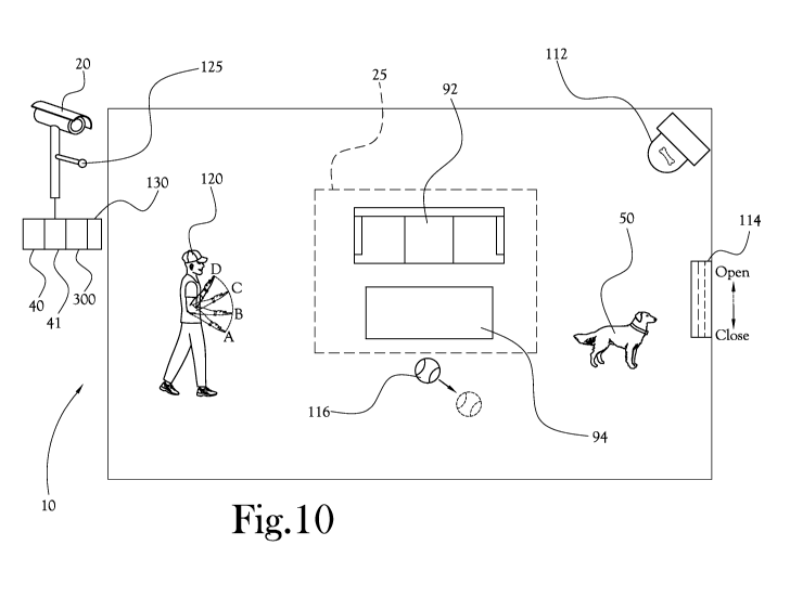
[0042] FIG. 10 is a perspective view of a system environment
illustrating a
user 120 providing control signals to the camera 20 in accordance with an
example
CA 02851154 2014-04-03
WO 2013/052863
PCT/US2012/059052
embodiment of the present general inventive concept. In this example
embodiment,
the controller 40 recognizes images displayed in the camera field of view,
such as
the user's hand movements from A to D displaying the user's arm bending from a
lower position to an upper position with their palm upward. Here, the
controller 40
5 can analyze the user's movement captured by the camera 20, and can
compare the
movement with predetermined image information stored in the controller 40, for
example in a lookup table, to determine whether the user performed a
recognizable
command. If so, the system can transmit a signal to the animal and/or to
associated devices via the transmitter 300. Example devices include a treat
10 dispenser 112, pet door 114, toy 116, and receiver collar 51, but a
variety of
different signals and/or devices could be used without departing from the
scope
and spirit of the present general inventive concept. In FIG. 10, the user's
gesture
could be interpreted, for example, to open or close the pet door 114, to
dispense a
pet treat 112, to activate a toy 116, or to transmit a stimulus to the animal
50 via
15 the receiver collar 51. The system can also include a microphone 125 to
detect
audible sounds, such as barks, to help determine whether corrected action is
required, as well as to speak to the animal if needed. For example, a
microphone
125 could be used to trigger a stimulation signal when nuisance barking is
detected. Further, microphone 125 and speaker 130 could be used to facilitate
bi-
directional internet communication, for example to communicate with the animal
remotely, if desired, both visually and audibly, to calm or praise the dog, as
needed.
[0043] FIG. 11 is a block diagram of a camera-based control system
configured in accordance with an example embodiment of the present general
inventive concept. The example system includes a camera 20, controller 40,
transmitter 300, network 1100, and controlled device 510. The controller 40
can
determined whether a detected image from the camera 20 warrants the
transmitter
300 to transmit a control signal to the pet and/or device 510. The transmitter
300
can be connected to a network 1100, wired or wireless, to transmit signals,
such as
notification signals, to a remote user in the event the pet 50 approaches or
escapes
a boundary zone. For example, the transmitter 300 can transmit email, text,
telephonic, pager, or other known or later developed messaging protocols to
the
user to notify the user that the pet, or other object, is approaching or
escaping the
predetermined boundary 25. The user can also transmit control signals to the
pet
CA 02851154 2014-04-03
WO 2013/052863
PCT/US2012/059052
16
and/or device 510 to remotely generate a stimulation signal over the internet
while
viewing the camera 20.
[0044] The transmitter / receiver link can be configured as a wired or
wireless link, including but not limited to, RF, WiFi, Bluetooth, Ethernet,
IR,
Soundwave. Thus, the system can allow a user to interact with a pet and
associated devices when the user is in the field of view of the camera along
with the
pet, or remotely.
[0045] It is noted that the simplified diagrams and drawings do not
illustrate
all the various connections and assemblies of the various components, however,
those skilled in the art will understand how to implement such connections and
assemblies, based on the illustrated components, figures, and descriptions
provided herein, using sound engineering judgment.
[0046] Embodiments of the present general inventive concept provide
behavior recognition systems and methods of identifying pet activities to
trigger a
customized reaction. Examples include, but are not limited to, bad behavior,
good
behavior, eating, sleeping, running, jumping, counter surfing, playing, etc.
[0047] It is possible to visualize the displays to see a pet on smart
phone or
computer connected to internet and to remotely see and interact with the pet
using
two-way voice. The escape warning signals can be implemented via email, text,
voicemail, push notification on a mobile device, social network, etc.
[0048] The camera can take boundary testing snapshots and escape
snapshots. It is possible to identify an intruder in the boundary snapshots,
for
example, other dogs, people, etc.
[0049] It is possible to incorporate car recognition systems into the
pet
containment system so as to create auto boundary adjustments where the
boundary is close to a road.
[0050] A reactive boundary can be used to judge the speed of pet and
adjust
the boundary for a longer correction signal. The system can identify potential
threats to the pet and adjust the boundary accordingly. The system can
identify
CA 02851154 2014-04-03
WO 2013/052863
PCT/US2012/059052
17
changes in recognized objects, such as moved furniture, and can adjust the
boundary accordingly.
[0051] The visual recognition system can be configured for pet
identification,
i.e., pet face recognition, to recognize pets and intruding animals.
[0052] The system can interact with remote toys and other stimulation
techniques and systems.
[0053] In some embodiments, the controller can share video feed from
the
camera in order to interact with the pet through social networking sites and
apps
(phone, tablet, computer, etc.)
[0054] It is possible to set-up multiple remote cameras to follow pets
throughout the house. The system can remotely actuate devices using the
stimulation signals for fun, convenience or conservation (i.e. to enable
feeding
systems, watering systems, warming beds, toys, unlock/open pet doors, open
doors, ring doorbells, wired/wireless fence systems, electronic collars, etc.,
based
on the tracked location of the pet relative to a predetermined border).
[0055] The present general inventive concept can be embodied as
computer-
readable codes on a computer-readable medium. The computer-readable medium
can include a computer-readable recording medium and a computer-readable
transmission medium. The computer-readable recording medium is any data
storage device that can store data as a program which can be thereafter read
by a
computer system. Examples of the computer-readable recording medium include
read-only memory (ROM), random-access memory (RAM), CD-ROMs, DVDs,
magnetic tapes, floppy disks, and optical data storage devices. The computer-
readable recording medium can also be distributed over network coupled
computer
systems so that the computer-readable code is stored and executed in a
distributed
fashion. The computer-readable transmission medium can transmit carrier waves
or signals (e.g., wired or wireless data transmission through the Internet).
Also,
functional programs, codes, and code segments to accomplish the present
general
inventive concept can be easily construed by programmers skilled in the art to
which the present general inventive concept pertains.
CA 02851154 2014-04-03
WO 2013/052863
PCT/US2012/059052
18
[0056] Numerous variations, modifications, and additional embodiments
are
possible, and accordingly, all such variations, modifications, and embodiments
are
to be regarded as being within the spirit and scope of the present general
inventive
concept. For example, regardless of the content of any portion of this
application,
unless clearly specified to the contrary, there is no requirement for the
inclusion in
any claim herein or of any application claiming priority hereto of any
particular
described or illustrated activity or element, any particular sequence of such
activities, or any particular interrelationship of such elements. Moreover,
any
activity can be repeated, any activity can be performed by multiple entities,
and/or
any element can be duplicated.
[0057] While the present general inventive concept has been
illustrated by
description of several example embodiments, it is not the intention of the
applicant
to restrict or in any way limit the scope of the inventive concept to such
descriptions and illustrations. Instead, the descriptions, drawings, and
claims
herein are to be regarded as illustrative in nature, and not as restrictive,
and
additional embodiments will readily appear to those skilled in the art upon
reading
the above description and drawings.