Note: Descriptions are shown in the official language in which they were submitted.
CA 02851698 2014-05-12
CYLINDER CLAMP
TECHNICAL FIELD
[0001] This document relates to cylinder clamps.
BACKGROUND
[0002] Many industries use cylinders for a variety of purposes. One such
industry is
the welding industry, which uses cylinders for storing pressurized acetylene
and oxygen to
provide torch fuel. The pressurized gas comes in a plurality of tall metal
cylinders, which
must be safely stored until and after use. Such cylinders are often stored in
an upright
orientation in a shop or other storage area. To keep the cylinders from
toppling, the cylinders
are secured to a wall or adjacent equipment such as on a cylinder skid or
trolley. Some
securing methods currently in used include chains and ropes strapped to or
around the
cylinders. Other methods include mechanical screw devices and other devices
that involve a
physical step to secure the object after placement in the required location.
SUMMARY
[0003] A cylinder clamp, comprising: a base member having parts that
together
define an opening for receiving a cylinder; a first arm and a second arm
mounted to the base
member at respective pivots, the first arm and the second arm being linked so
that the arms
move together; and a stop member movable between a locked position in which
the stop
member binds at least the first arm and the base member and an open position
in which the
stop member is out of binding contact with either or both of the first arm and
the base
member.
[0004] In various embodiments, there may be included any one or more of
the
following features: The base member is planar. The base member has one or more
mounts
for connecting to an external working surface. The first arm and second arm do
not meet
when in the locking position. In the open position the first arm and second
arm are spaced
sufficiently to allow the entry of the cylinder. In the locked position the
first arm and second
arm extend more than two hundred seventy degrees around a cylinder receptacle
defined by
CA 02851698 2014-05-12
the first and second arms. The stop member comprises a pin extended, in the
locked position,
through an opening in the first arm and an opening in the base member. The
opening in the
first arm and the opening in the base member are misaligned in the open
position and aligned
in the locked position. The stop member is biased to extend into the opening
in the base
member. The stop member comprises a handle to retract the pin from the locked
position.
The pin is mounted directly or indirectly on the first arm. The first arm and
second arm are
linked via a lever, and the lever mounts the pin. For each of the first arm
and the second
arm, the pivot is located between a jaw portion and a rear extension, in which
the first arm
and the second arm are linked by cooperating arcuate toothed surfaces on each
of the rear
extensions. A combination of the cylinder clamp and a cylinder locked in the
locked position
within the opening. The cylinder contains pressurized gas or liquid. The
cylinder is empty or
is a cylinder that is used for applications other than the storage of
pressurized gas or liquid.
[0005] These and other aspects of the device and method are set out in the
claims,
which are incorporated here by reference.
BRIEF DESCRIPTION OF THE FIGURES
[0006] Embodiments will now be described with reference to the figures, in
which
like reference characters denote like elements, by way of example, and in
which:
[0007] Figs. 1 and 2 are top views, partially in section, illustrating a
closing sequence
of a cylinder clamp, with the base plate not shown.
[0008] Figs. 3 and 4 are perspective views of Figs. 1 and 2, respectively,
with the
base plate shown in Fig. 3 only.
[0009] Fig. 5 is a section view taken along the section lines 5-5 in Fig.
2.
[0010] Fig. 6 is a perspective view of a second embodiment of a cylinder
clamp.
DETAILED DESCRIPTION
[0011] Immaterial modifications may be made to the embodiments described
here
without departing from what is covered by the claims.
[0012] A gas cylinder is a pressure vessel used to store gases at above
atmospheric
pressure. High pressure gas cylinders are also called bottles. The
transportation and storage
2
CA 02851698 2014-05-12
of high pressure cylinders is regulated by many governments throughout the
world. Because
the contents are under pressure and are sometimes hazardous, there are special
safety
regulations for handling gas cylinders. These include chaining bottles to
prevent falling and
breaking, proper ventilation to prevent injury or death in case of leaks and
signage to
indicate the potential hazards. Installing and replacing gas cylinders should
be done by
trained personnel. If a compressed gas cylinder tips over, causing the valve
block to be
sheared off, the rapid release of high pressure gas may cause the cylinder to
be violently
accelerated, potentially causing property damage, injury, or death. To prevent
this, cylinders
are normally secured to a fixed object or transport cart with a strap or
chain.
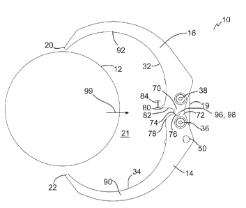
[0013] Referring to Fig. 3, a cylinder clamp 10 is illustrated, comprising
a base
member 18, a first arm 14, a second arm 16, and a stop member 63. The base
member 18 has
parts that together define an opening 21 (Fig. 1) for receiving a cylinder 12.
The parts of the
base member 18 include in the example shown a first arm 81, a second arm 82,
and an
arcuate inner profile 85 corresponding to the curved outer profile of a
cylinder 12 (Fig. 3).
The base member 18 may be planar, for example in the base plate form shown, or
may at
least have a planar under surface (not shown). The base member 18 may have one
or more
mounts, such as oblong apertures 30 or circular apertures 28, for connecting
to an external
working surface (not shown). The external working surface may include a ground
surface,
wall surface, or surface on another piece of equipment such as a clamp
connected to the wall
or ground, or a trolley, skid, or other movable transportation surface.
[0014] Referring to Fig. 1, first arm 14 and second arm 16 may be mounted
to the
base member 18 at respective pivots, such as bolt posts 36 and 38,
respectively. Referring to
Fig. 3, the first arm 14 and the second arm 16 may be linked, for example
using a lever 58,
so that the arms move together. Moving together includes opening and closing
together, so
that movement by one arm moves the other arm, and vice versa. Similarly, when
movement
of one arm is impeded, movement of the other arm may be impeded.
[0015] Referring to Figs. 3 and 4, a stop member 63, and the entire
cylinder clamp
10, may be movable between a locked position (Fig. 4) and an opened position
(Fig. 3).
Referring to Fig. 4, in the locked position the stop member 63 binds at least
the first arm 14
and the base member 18. In some cases the stop member 63 is in binding contact
with both
3
CA 02851698 2014-05-12
arms 14 and 16 in the locked position. However, only one arm 14 or 16 need be
bound to
prevent movement of both arms 14 and 16 since arms 14 and 16 move together.
Referring to
Fig. 3, in the open position the stop member 63 is out of binding contact with
either or both
of the first arm 14 and the base member 18.
[0016] Referring to Figs. 1, 2, 3, 4 and 5, the stop member 63 may
comprise a pin 54.
Pin 54 may extend, in the locked position (Figs. 2 and 4), through an opening
50 in the first
arm 14 and an opening 52 in the base member 18. The opening 50 in the first
arm 14 and the
opening 52 in the base member 18 may be misaligned in the open position (Figs.
1 and 3)
and aligned in the locked position (Figs. 2 and 4). The pin 54 may be biased,
for example by
a spring 62, to extend into the opening 52 in the base member 18. The pin 54
may be
mounted directly or indirectly (shown) on the first arm 14. For example,
indirect mounting is
shown because the pin 54 is directly mounted on a holder or bracket 66 that
includes lever 58
connected to both pivots 36 and 38. Bracket 66 includes an upstanding wall 56
originating
from lever 58 at a ninety degree angle to wall 56, and terminating in a top
plate 64 through
which pin 54 passes. A spring 62 is compressed in the opened position along a
portion of the
length of pin 54 between a protrusion, shoulder, or set screw 68 and top plate
64. Thus, as
arms 14 and 16 move into the locked position from Fig. 3, as soon as holes 50
and 52 align
the spring 62 pushes the pin 54 through holes 50 and 52 to bind further
movement. A handle
60 with a hand grip 61 may be present on pin 54 to permit a user to manually
retract the pin
54 from the locked position. Upon retraction the cylinder 12 may be removed
from the
clamp 10 by imparting a lateral force on the cylinder 12 away from opening 21.
Once
unlocked the ends Fig. 6 illustrates a second configuration of clamp 10 with a
pin bracket 66
that is a mirror image of the pin bracket 66 of Fig. 3.
[0017] Referring to Figs. 1, 2, and 5, the arms 14 and 16 may link by a
suitable
mechanism. For example, for each of the first arm 14 and the second arm 16,
the pivot 36 or
38 may be located between a jaw portion 90, 92 and a rear extension 70, 72,
respectively
(Fig. 1). The first arm 14 and the second arm 16 may be linked by cooperating
arcuate
toothed surfaces 74 and 76, respectively, on each of the rear extensions 70,
72, respectively.
The extensions 70 and 72 are shaped to prevent over-opening past the point
shown in Fig. 1,
while permitting collective closing to the position shown in Fig. 2. There are
several design
4
CA 02851698 2014-05-12
mechanisms to facilitate such function in the example shown. Firstly, arcuate
protrusion 74
of arm 16 meshes like a gear tooth with a corresponding arcuate recess 76 in
arm 14. Thus,
pivoting movement of one arm is transmitted to the other like a gear. Second,
butt portions
96, 98 of extensions 70, 72, respectively, are shaped to extend across cross
paths during
opening so that butt portions 96 and 98 limit the travel of arms 14 and 16.
Butt portions 96
and 98 include matching surfaces that cooperate to stop the arms 14, 16 from
overextending
by rendering the arms inoperative after a predetermined degree of opening.
Referring to Fig.
5, such may be accomplished by having one portion 98 extend past the midpoint
between
pivots 38 and 40 in an opened position.
[0018] Referring to Figs. 1 and 2, articulating arms 14 and 16 may be
designed to
close upon contact with a cylinder 12 entering the opening 21. For example, an
inward
protrusion 80 on an inward facing surface 34 of arm 16 may extend into opening
21 from
arm 16. When viewed along an entry axis 99 of cylinder 12, protrusion 80 is
spaced a lateral
distance 84 from pivot 36. Thus, contact between protrusion 80 and cylinder 12
will transmit
torque to arm 16, rotating arm 16. Because protrusion 80 is located on rear
extension 72 of
arm 16, the torque operates to close the arm 16 over the cylinder. Because
arms 14 and 16
are linked to move together, both arms 14 and 16 thus close in unison to at
least partially
encircle an outer circumference of the cylinder 12 as shown in Fig. 2. A
corresponding
cutout 78 may be present on an inner surface 34 of arm 14 to avoid
interference with
protrusion 80 on closing.
[0019] The first arm 14 and second arm 16 may not meet when in the locking
position (Fig. 2). For example, the first jaw 14 and second jaw 16 may extend
more than two
hundred seventy degrees around a cylinder receptacle 21 defined by the first
and second
arms 14, 16, when in the locked position. An exemplary angle of separation is
defined
between lines 24, 26 drawn from ends 20 and 22 of arms 16 and 14 and meeting
at the
interface between arms 14 and 16. In other cases ends 20 and 22 may meet when
closed, for
example at diametrically opposite positions relative to the interface between
arms 14 and 16.
[0020] Referring to Fig. 5 pivots 36 and 38 may be formed by suitable
mechanisms.
For example, bolts 44 are shown, with washers 40 and locking nuts 42 securing
the bolts 44
in place. The base member 18 may include a mount plate, such as an inert
spacer 19,
CA 02851698 2014-05-12
connected to the base plate or member 18 and mounting the arms 14 and 16 using
pivots 36
and 38, respectively. Other pivots may be provided for example with rivets
(not shown).
[0021] In the open position the first arm and second arm are spaced
sufficiently to
allow the entry of the cylinder. In the example shown the opening 21 when in
the locked
position has roughly the same dimensions as the cylinder 12. However, in other
cases the
cylinder 12 will be smaller than the closed opening 21. In such cases one or
more spacers
may be added for example using clips to one or more of the cylinder 12, arm
14, or arm 16 to
sufficiently fill the void space that would otherwise be left in the clamp
when locked around
such a cylinder 12. For example one or more crescent shaped spacers may be
attached
around at least part of the circumference of the cylinder or along the inner
arcuate surfaces
32 or 34 of the arms 14 or 16. Another way to fit various sizes of cylinders
is to use slidable
pivots that can lock in various positions as in adjustable pliers.
[0022] The cylinder clamp 10, which may also be referred to as a cylinder
bracket or
bottle clamp, may be used to secure any object with a cylindrical form whether
containing
pressurized or unpressurized gas, liquids. The cylinder may also be empty.
Cylinders include
cylindrical vertical standing objects. A cylinder may also be stored, using
the clamp 10, in a
fixed location. In some cases non-cylindrical objects may be secured using the
clamp 10,
including columns, I-beams, building materials, and various containers. In
some cases
cylindrical objects that are not intended for use to store pressurized gases
or liquids may be
secured, for example well tubulars, pipes, conduits, cylindrical columns, and
others,
including hollow, solid, and capped end cylinders. Some embodiments disclosed
here may
lock a cylinder in place without the need for added fixtures, tools, parts or
steps other than
moving the cylinder 12 into the opening 21. Thus, the cylinder 12 is
automatically locked in
place upon entry. The clamp 10 may be made out of materials that make the
clamp impact
resistant and not susceptible to deterioration in hazardous corrosive
environments as current
devices, chains, straps and cables deteriorate.
[0023] Other components may be present that are not described here. The
base 18
may be positioned above the arms 14 and 16 in use in some cases if the clamp
10 is used
upside down. Clamp 10 may be used in other configurations such as in a
vertical orientation
mounting a horizontal cylinder 12 for example. Cylinders may be used for
welding in a
6
CA 02851698 2014-05-12
machine shop, on location, or other applications. Cylindrical form containers
may also be
used in schools, laboratories, welding shops, gas suppliers or any
manufacturing or storage
facility.
[0024] In the claims, the word "comprising" is used in its inclusive sense
and does
not exclude other elements being present. The indefinite articles "a" and "an"
before a claim
feature do not exclude more than one of the feature being present. Each one of
the individual
features described here may be used in one or more embodiments and is not, by
virtue only
of being described here, to be construed as essential to all embodiments as
defined by the
claims.
7