Note: Descriptions are shown in the official language in which they were submitted.
CA 02851877 2014-04-10
WO 2013/059315
PCMJS2012/060608
DUAL USE CABLE WITH FIBER OPTIC PACKAGING
FOR USE IN WELLBORE OPERATIONS
BACKGROUND
[0001] The present disclosure is related in general to wellsite equipment such
as oilfield surface equipment, downhole assemblies, and the like.
[0002] The statements made herein merely provide information related to the
present disclosure and may not constitute prior art, and may describe some
embodiments illustrating the invention. All references discussed herein,
including patent and non-patent literatures, are incorporated by reference
into
the current application.
[0003] Coiled tubing is used in such oilwell operations as fluid pumping,
fracturing, acidizing, and drilling. The fluids pumped through the coiled
tubing
may also used to activate downhole tools, and pressure variations in the fluid
can be monitored to obtain basic information on downhole conditions. Data can
be transmitted inside the coiled tube using fiber optic cables, typically
consisting
of small-diameter metallic tubes that contain a number of optical fibers.
These
cables can be inserted into the coiled tubing at the well surface by pumping
them
through coiled tubing at the take-up spool. When the fiber optic cable reaches
the tool-end of the coiled tubing it is attached to the tool as needed.
[0004] There are issues concerning typical fiber optic cables disposed in
metallic tubes used in coiled tubing, such as an increased size of the
metallic
tube creating stiffness and/or pumpability issues, the size of the metallic
tubes
limits the amount of area available for electrical power transmission, and the
metallic tube's overall strength-to-weight ratio, which may limit the depth
capability of the metallic tube.
[0005] It remains desirable to provide improvements in oilfield equipment
and/or downhole assemblies.
CA 02851877 2014-04-10
WO 2013/059315
PCT/US2012/060608
SUMMARY
[0006] The fiber optic cable embodiments provide solutions to all of the
above-described issues. Jacketing/tubing options include polymeric layers to
mitigate the possibility of damage from pinholes. The embodiments offer
greater
protection of optical fibers resulting in decreased signal attenuation and
optical
fiber failure. The embodiments are also more resistant to collapse under
torque
stresses.
[0007]The embodiments described herein provide fiber optic cables including
polymers to form crush-resistant tubes that better protect the optical fibers.
All
embodiments include polymeric jacketing to substantially eliminate optical
fiber
damage from fluids entering through pinholes in a metallic outer tube. All
embodiments also include segregated, insulated metallic components that can
be used as electrical conductors.
[0008] A method for performing an operation in a wellbore penetrating a
subterranean formation utilizing a dual use cable for transmitting electrical
power
and data in wellbore operations, comprises method for performing an operation
in a wellbore providing a dual use cable, the dual use cable comprising at
least
one longitudinally extending optical fiber a first metallic component
surrounding
the at least one optical fiber a polymer material layer surrounding and
encasing
the first metallic component wherein the at least one optical fiber is adapted
to
transmit data and the first metallic component is adapted to transmit at least
one
of electrical power and data, and a second metallic component formed as at
least one of an outer metallic tube and a plurality of armor wire strength
members and another polymer material layer surrounding and encasing the
polymer layer material, the second metallic component embedded in the another
polymer material layer, disposing the dual use cable in the wellbore, and
performing at least one wellbore operation with the cable. In an embodiment,
the at least one optical fiber is positioned in a fiber optic micro-cable
having at
least another optical fiber. In an embodiment, the first metallic component is
one
of a tube, a split-tube and a slotted armor or copper wire.
2
CA 02851877 2014-04-10
WO 2013/059315
PCT/1JS2012/060608
[0009] In an embodiment, the at least one of the polymer material layer and
the
another polymer material layer is formed of a CFR-Fluoropolymer, non-
reinforced fluoropolymer, or PEEK material. In an embodiment, the wellbore
operation comprises at least one of a fluid pumping operation, a fracturing
operation, an acidizing operation, a drilling operation, and a coiled tubing
operation. In an embodiment, the method further comprises encasing the dual
use cable having the armor wire strength members embedded in the another
polymer material layer in a metallic tube. In an embodiment, the method
further
comprises disposing the dual use cable in a length of coiled tubing and
wherein
the dual use cable does not substantially reduce the amount of internal area
or
volume within the coiled tubing for performing the wellbore operation. In an
embodiment, the method further comprises forming the first metallic component
from an inner split-tube and an outer split-tube spaced apart by a layer of
polymer material. In an embodiment, the method further comprises forming the
first metallic component from an inner tube and an outer split-tube.
[0010] A dual use cable for transmitting electrical power and data in wellbore
operations comprises at least one longitudinally extending optical fiber a
first
metallic component surrounding the at least one optical fiber, a polymer
material
layer surrounding and encasing the first metallic component wherein the at
least
one optical fiber is adapted to transmit data and the first metallic component
is
adapted to transmit at least one of electrical power and data, and a second
metallic component surrounding and encasing the polymer material layer, the
second metallic component formed as at least one of an outer metallic tube and
a plurality of armor wire strength members embedded in another polymer
material layer, wherein the dual use cable is disposed within a length of
coiled
tubing and wherein the dual use cable does not substantially reduce the amount
of internal area or volume within the coiled tubing for performing the
wellbore
operation. In an embodiment the cable further comprises a plurality of the
longitudinally extending optical fibers, the first metallic component being a
thin
metallic tube, the polymer material layer being formed of a CFR-Fluoropolymer,
non-reinforced fluoropolymer, or PEEK material, and the second metallic
component being a metallic tube.
3
81779011
[0011] In an embodiment, the at least one longitudinally extending optical
fiber is a fiber
optic micro-cable, the first metallic component is a split-tube, and the
second metallic
component is two layers of armor wire strength members embedded in polymer
material.
The cable may further comprise an outer metallic tube surrounding the second
metallic
component. In an embodiment, the cable further comprises plurality of the
longitudinally
extending optical fibers, the first metallic component being a metallic tube,
and the
second metallic component being two layers of armor wire strength members
embedded
in polymer material. In an embodiment, the cable further comprises a plurality
of the
longitudinally extending optical fibers, the first metallic component being a
plurality of
slotted armor wires each receiving an associated one of the optical fibers in
a
longitudinally extending slot, and the second metallic component being a layer
of armor
wire strength members embedded in polymer material. In an embodiment, the
cable
further comprises a plurality of the longitudinally extending optical fibers,
the first metallic
component being a first split-tube surrounding the optical fibers and a second
split-tube
surrounding the first split-tube, and the second metallic component being two
layers of
armor wire strength members embedded in polymer material. In an embodiment,
the
cable further comprises a plurality of the longitudinally extending optical
fibers, the first
metallic component being a tube surrounding the optical fibers and a split-
tube
surrounding the tube, and the second metallic component being two layers of
armor wire
strength members embedded in polymer material and surrounded by a polymer
outer
jacket. In an embodiment, the cable is adapted to perform at least one
wellbore
operation. The wellbore operation may be performed in conjunction with at
least one
coiled tubing operation.
[0011a] According to an embodiment, there is provided a method for performing
an
operation in a wellbore penetrating a subterranean formation utilizing a dual
use cable for
transmitting electrical power and data in wellbore operations, comprising:
providing a
dual use cable, the dual use cable comprising at least one longitudinally
extending
optical fiber; a first metallic component surrounding the at least one optical
fiber; a
polymer material layer surrounding and encasing the first metallic component
wherein
the at least one optical fiber is adapted to transmit data and the first
metallic component
is adapted to transmit at least one of electrical power and data; and a second
metallic
4
CA 2851877 2019-02-25
81779011
component formed as at least one of an outer metallic tube and a plurality of
armor wire
strength members and another polymer material layer surrounding and encasing,
the
polymer layer material, the second metallic component embedded in the another
polymer
material layer; disposing the dual use cable in a length of coiled tubing; and
disposing the
dual use cable and the coiled tubing in the wellbore; and performing at least
one wellbore
operation with the cable and coiled tubing, wherein the outer diameter of the
dual use
cable does not substantially reduce the amount of internal area or volume
within the
coiled tubing for performing the wellbore operation.
[0011b] According to another embodiment, there is provided a dual use cable
for
transmitting electrical power and data in wellbore operations, comprising: at
least one
longitudinally extending optical fiber; a first metallic component surrounding
the at least
one optical fiber; a polymer material layer surrounding and encasing the first
metallic
component wherein the at least one optical fiber is adapted to transmit data
and the first
metallic component is adapted to transmit at least one of electrical power and
data; and a
second metallic component surrounding and encasing the polymer material layer,
the
second metallic component formed as at least one of an outer metallic tube and
a
plurality of armor wire strength members embedded in another polymer material
layer,
wherein the dual use cable is disposed within a length of coiled tubing and
wherein the
outer diameter of the dual use cable does not substantially reduce the amount
of internal
area or volume within the coiled tubing for performing the wellbore operation.
BRIEF DESCRIPTION OF THE DRAWINGS
[0012] These and other features and advantages will be better understood by
reference
to the following detailed description when considered in conjunction with the
accompanying drawings.
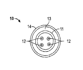
[0013] Fig. 1 is a radial cross-sectional view of a first embodiment of a
fiber optic Gable
according to the disclosure.
4a
CA 2851877 2019-02-25
CA 02851877 2014-04-10
WO 2013/059315
PCT/1JS2012/060608
[0014] Figs. 2A through 2G are radial cross-sectional views of a second
embodiment of a fiber optic cable according to the disclosure.
[0015] Figs. 3A and 3B are radial cross-sectional views of variations of the
second embodiment fiber optic cable shown in Fig. 2G.
[0016] Figs. 4A through 4F are radial cross-sectional views of a third
embodiment of a fiber optic cable according to the disclosure.
[0017] Figs. 5A through 5E are radial cross-sectional views of a fourth
embodiment of a fiber optic cable according to the disclosure.
[0018] Figs. 6A through 6E are radial cross-sectional views of a fifth
embodiment of a fiber optic cable according to the disclosure.
[0019] Figs. 7A through 7E are radial cross-sectional views of a sixth
embodiment of a fiber optic cable core according to the disclosure.
[0020] Figs. 8A through 8C are radial cross-sectional views of variations of a
fiber optic cable incorporating the core shown in Fig. 7E.
[0021] Fig. 9 is a radial cross-sectional view of a further embodiment fiber
optical cable according to the disclosure.
[0022] Fig. 10A is a radial cross sectional view of the cable shown in Fig. 9
installed in a coiled tubing and Fig. 10B is a schematic view of a tool
attached to
the coiled tubing and cable of Fig. 10.
[0023] Figs. 11A through 11H are radial cross-sectional views of an embodiment
of a cable.
[0024] Figs. 12A through 12H are radial cross-sectional views of an embodiment
of a cable.
CA 02851877 2014-04-10
WO 2013/059315
PCT/1JS2012/060608
DETAILED DESCRIPTION
[0025] While the cable embodiments are only shown in cross-sectional views,
it is to be understood that the components of the cables extend in a
longitudinal
direction between the ends of the cables. Referring now to Fig. 1, there is
shown a first embodiment fiber optic cable 10. The first embodiment cable 10
differs from conventional embodiments in that there is a layered construction
of
its outer tube. Instead of a solid metallic tube, the cable 10 begins with a
first
metallic component in the form of an inner thin metallic tube 11 which encases
a
number of optical fibers 12. Although four optical fibers 12 are shown, more
or
less fibers can be used. A jacket or layer 13 of polymer material, such as,
but
not limited to, carbon-fiber-reinforced (CFR) Fluoropolymer material is
extruded
over the central metallic tube 11. A second metallic component in the form of
an
outer metallic tube 14 is drawn over the CFR-Fluoropolymer layer to complete
the cable 10. The layered tube embodiment 10 offers greater crush and torque
resistance than a single solid metallic tube. The polymeric layer 13 provides
a
seal against any fluid penetrating through pinholes in the outer metallic tube
14.
In addition, because the polymer material provides a layer 13 of electrical
insulation between the metallic tubes 11 and 14, the two metallic tubes can be
used as electrical conductors, with the inner metallic tube 11 used as a
positive
conductor and the outer metallic tube 14 used as the return.
[0026] Referring now to Figs. 2A through 2G, there is shown a second
embodiment fiber optic cable 20, during steps of a cable construction method .
A fiber-optic micro-cable 21 is placed within a first metallic component in
the
form of a split-tube conductor 22 surrounded by a second metallic component in
the form of a caged armor 23a , 23b surrounded by a third metallic component
in
the form of an outer metallic tube 24. The split tube 22 can be used to
provide
electrical power to downhole tools with the armor wires 23a and/or 23b used as
a return path. The numbers and arrangement of the armor wires 23a and 23b in
two strength member layers are utilized to minimize torque imbalance. A
"caged" in a CFR-Fluoropolymer jacketing system adds strength to the cable 20
and protects against damage from fluids penetrating through pinholes in the
6
CA 02851877 2014-04-10
WO 2013/059315
PCMJS2012/060608
outer metallic tube 24. A method of construction of the cable 20 is
illustrated in
Figs. 2A-2G as described below.
[0027] The method of construction begins with a step of providing the fiber-
optic micro-cable 21 which serves as the cable core, as shown in Fig. 2A
(though illustrated as a three fiber cable those skilled in the art will
appreciate
that a four-fiber or other configuration core may also be used). In a second
step
shown in Fig. 2B, the split tube 22 made of a conductive metal (such as,
copper)
is placed over the micro-cable cable core 21 and a first layer 25 of polymer
material is extruded over the split tube 22 to hold the two split halves in
place. In
a third step shown in Fig. 2C, an inner layer of the armor wire strength
members
23a is cabled at a lay angle over the polymer-coated split tube 22. In a
fourth
step shown in Fig. 2D, a second polymer layer 26 of CFR-Fluoropolymer
material, or other suitable polymer material, is extruded over and encases the
armor wire strength members 23a.
[0028] As shown in Fig. 2E, a second layer of the armor wire strength
members 23b is cabled (at a counter-helical lay angle to the first armor wire
layer 23a shown in Fig. 2C) over the CFR-Fluoropolymer layer 26 in a fifth
step
of the method. Fig. 2F shows a sixth step in which a third polymer layer 27 (a
second layer of the CFR-Fluoropolymer material) is extruded over and encases
the second layer of armor wires 23b. The two layers 26 and 27 of CFR-
Fluoropolymer material bond to each other and to the polymer material first
layer
25 coating the split tube 22 to create a bonded jacketing system to complete a
cable 20a. As an option, the metallic tube 24 can be drawn over the outer CFR-
Fluoropolymer layer 27 to enhance stiffness and form the cable 20 as shown in
Fig. 2G.
[0029] There is shown in Figs. 3A and 3B variations of the second
embodiment cable 20 shown in Fig. 2G. A cable 30a shown in Fig. 3A
comprises essentially the same construction as the cable 20 shown in Fig. 2G
with the exception of the outer layer of strength members 23b added to the
cable
20 in Step 5. In the cable 30a, these outer strength members 23b comprise
stranded wire 31b. Similarly, a cable 30b shown in Fig. 3B is of the same
7
CA 02851877 2014-04-10
WO 2013/059315
PCMJS2012/060608
construction as the cable 20 as shown in Fig. 2G with the exceptions that the
armor wire strength members 23a and 23b added to the cable 20 in Steps 3 and
respectively are replaced with stranded wire strength members 31a and 31b
respectively.
[0030] Referring now to Figs. 4A through 4F, there is shown a third
embodiment fiber-in-metal-tube (FIMT) based cable 40 , during steps of a cable
construction method . A cable core is surrounded by a bonded caged-armor
jacketing system, discussed in more detail below. A metallic portion of the
FIMT
cable 40 may be used to provide electrical power to downhole tools with armor
wires used as a return path. The numbers and arrangement of the armor wires
in two strength member layers are selected to minimize torque imbalance. The
caged CFR-Fluoropolymer jacketing system adds strength to the cable and
protects against the cable damage from fluids. As illustrated in Figs. 4A
through
4F, the cable 40 may be constructed according to the following method steps.
[0031] The construction begins with a first step wherein the FIMT cable 41
which serves as the cable core is provided as shown in Fig. 4A. The cable core
41 includes a first metallic component in the form of a metallic tube 42
surrounding a plurality of optical fibers 43. In a second step shown in Fig.
4B, a
layer 44 of polymer material is extruded over the FIMT core 41 and the
metallic
tube 42 can be used as an insulated conductor. An inner layer of armor wire
strength members 45a is cabled at a lay angle over the FIMT core 41 in a third
step, as shown in Fig. 4C, and the inner layer of armor wires can be used as
electrical conductors. In a fourth step shown in Fig. 4D, a second layer 46 of
CFR-Fluoropolymer material, or other suitable polymer material, is extruded to
encase the armor wire strength members 45a. In a fifth step shown in Fig. 4E,
a
second layer of armor wire strength members 45b is cabled (at a counter-
helical
lay angle to the first armor wire layer 45a shown in Fig. 4C) over the CFR-
Fluoropolymer layer 46 and these outer armor wires can be used as electrical
conductors. Either or both of the layers of armor wire strength members form a
second metallic component. In a final sixth step shown in Fig. 4F, a third
polymer layer 47 of CFR-Fluoropolymer material is extruded over and encases
the second layer of armor wires 45b. The two layers 46 and 47 of CFR-
8
CA 02851877 2014-04-10
WO 2013/059315
PCT/1JS2012/060608
Fluoropolymer material bond to each other and to the first polymer layer 44
coating the FIMT cable 41 to create a bonded jacketing system.
[0032] Referring now to Figs. 5A through 5E, there is shown a fourth
embodiment fiber optic cable 50 wherein individual optical fibers contained in
insulated split-tube conductors are cabled together in a CFR-Fluoropolymer
material jacket to serve as the cable core, surrounded by a bonded caged-armor
jacketing system, discussed in more detail below. The metallic portions of the
split-tubes can be used to provide electrical power to down hole tools. The
armor
wires also can be used as potential return paths. "Caging" the armor wires in
a
CFR-Fluoropolymer jacketing system adds strength to the cable and protects
against damage from fluids. The cable 50 is constructed according to the
following method steps of the invention.
[0033] The cable 50 begins with a cable core 51 having a first metallic
component in the form of a split-tube conductor 52 encasing a single optical
fiber
53 provided as shown in Fig. 5A. A first layer 54 of polymer material is
extruded
over the split-tube 52, creating an insulated conductor 55 in a second step,
as
shown in Fig. 5B. A number of these insulated split-tube electrical/fiber-
optic
conductors 55 are cabled together in an extrusion of a second polymer layer 56
of CFR-Fluoropolymer material to create a cable core in a third step, as shown
in
Fig. 5C. A second metallic component in the form of a layer of armor wire
strength members 57 is cabled at a lay angle over the cable core in a fourth
step
shown in Fig. 5D, and these armor wires 57 can also be used as electrical
conductors. In a fifth step shown in Fig. 5E, a third polymer layer 58 of CFR-
Fluoropolymer material, or other suitable polymer material, may be extruded
over to encase the armor wire strength members 57. The outer layer 58 of CFR-
Fluoropolymer material bonds to the core to create a bonded jacketing system.
A
second layer of solid armor may be placed counter helix to the armor 57,
followed by an outer CFR-Fluoropolymer jacket may also be given to the cable
50 similar to cable 20 and 40.
[0034] Referring now to Figs. 6A through 6E, there is shown a fifth
embodiment fiber optic cable 60 wherein individual optical fibers placed in
slots
formed in insulated slotted armor or copper wires can be cabled together in a
9
CA 02851877 2014-04-10
WO 2013/059315
PCMJS2012/060608
CFR-Fluoropolymer material jacket to serve as the cable core, surrounded by a
bonded, caged-armor jacketing system, discussed in more detail below. The
metallic portions of the slotted armor or copper wires can be used to provide
electrical power to downhole tools or the like. The caged armor wires may also
be used as potential return paths. "Caging" the armor wires in a CFR-
Fluoropolymer jacketing system adds strength to the cable and protects against
damage from fluids. As illustrated in Figs. 6A through 6E, the cable 60 can be
constructed as described in the following steps of the method .
[0035] The cable 60 begins with a first step shown in Fig. 6A wherein a cable
core 61 is formed by placing a single optical fiber 63 in a longitudinally
extending
slot 62a of a first metallic component in the form of a slotted armor or
copper
wire 62. In a second step shown in Fig. 6B, a first layer 64 of polymer
material is
extruded over the cable core 61 creating an insulated conductor 65. Several of
these insulated conductors 65 are cabled together in a second polymer layer 66
extrusion of a CFR-Fluoropolymer material to create a cable core according to
a
third step as shown in Fig. 6C. In a fourth step shown in Fig. 6D, a second
metallic component in the form of a layer of armor wire strength members 67 is
cabled at a lay angle over the cable core and these armor wires can also be
used as electrical conductors. In a fifth step shown in Fig. 6E, a third
polymer
layer 68 of CFR-Fluoropolymer material, or other suitable polymer material, is
extruded over to encase the armor wire strength members 67. The outer CFR-
Fluoropolymer layer 68 bonds to the core to create a bonded jacket for the
cable
60. A second layer of solid armor may be placed counter helix to the armors
67,
followed by an outer CFR-Fluoropolymer jacket may also be given to the cable
60 similar to cable 20 and 40.
[0036] Referring now to Figs. 7A through 7E, a sixth embodiment cable core
70 retains the strength and flexibility of the previous embodiments, first
through
sixth, and adds the ability to return electrical current on a separate
conductor
rather than on the armor wire strength members. In the cable core 70, three or
more optical fibers can be placed in a soft polymer material between two
layers
of split tube conductors. The layers of split tube conductors are separated by
layers of insulation so that each layer can be used as a separate conductor.
The
cable core 70 is completed by encasing the cable core in a polymeric jacketing
CA 02851877 2014-04-10
WO 2013/059315
PCMJS2012/060608
system consisting of a short-fiber-reinforced polymer material with multiple
layers of solid and/or stranded armor wires "caged" inside the polymer
material.
This embodiment allows current to be passed down one split-tube conductor and
returned on the other. In this embodiment, the electrical return on the armor
wires is not necessary. Referring now to Figs 7A through 7E, the basic
assembly process is described as follows.
[0037] In a first step shown in Fig. 7A, a number of optical fibers 71 are
placed
at a center of the cable core 70. In a second step shown in Fig. 7B, the
optical
fibers 71 are encased in a soft polymer material 72 as two halves of a split-
tube
conductor 73 are brought together to encase the optical fibers 71 and the soft
polymer material 72. Fig. 7C shows a third step in which a first layer 74 of
polymer material is extruded over the split-tube conductor 73 to hold the two
halves together and insulate the conductor. In a fourth step shown in Fig. 7D,
a
second, larger-diameter split-tube conductor 75 has a set of conductor halves
placed over the first polymer layer 74. Fig. 7E shows a fifth step in which a
second layer 76 of polymer material is extruded over the second split-tube
conductor 75 to hold the two halves together and insulate the outer conductor
of
the cable core 70. The split-tube conductors 73 and 75 form a first metallic
component.
[0038] Referring now to Figs. 8A through 8C, the caged armor polymeric
jacketing system (using an amended polymer material such as, but not limited
to, CFR-Fluoropolymer material) described above can be applied over the
completed cable core 70 of Fig. 7E, as described above, to produce several
possible arrangements of an armor jacketing system. As shown in Fig. 8A, a
fiber optic cable 80a is formed from the core 70 encased in an inner layer 81a
of
a polymer material and an outer layer 81b a polymer material. Embedded in the
layers 81a and 81b are solid armor wire strength members 82a and 82b
respectively. As shown in Fig. 8B, a fiber optic cable 80b is formed similar
to the
cable 80a except that the outer layer of solid armor wire strength members 82b
is replaced with an outer layer of stranded armor wire strength members 83b.
As shown in Fig. 8C, a fiber optic cable 80c is formed similar to the cable
80b
except that the inner layer of solid armor wire strength members 82a is
replaced
with an inner layer of stranded armor wire strength members 83a. The
11
CA 02851877 2014-04-10
WO 2013/059315
PCMJS2012/060608
combinations of the armor wire strength members 82a, 82b, 83a and 83b form a
second metallic component.
[0039] Referring now to Figs. 11A through 11H, a seventh embodiment cable
core 110 is shown. In the cable core 110, three or more optical fibers (four
are
illustrated) can be placed in a soft polymer material between a layer of split
tube
conductors. Drawn over the split tube conductors is a metallic tube, separated
from the split tube conductor by a layers of insulation. The cable core 110 is
completed by encasing the cable core in a polymeric jacketing system
consisting
of a short-fiber-reinforced polymer material with multiple layers of solid
and/or
stranded armor wires "caged" inside the polymer material. This embodiment
enhances the stiffness of the overall cable and cable core, discussed in more
detail below. Referring now to Figs 11A through 11H, the basic assembly
process is described as follows.
[0040] Referring now to Fig. 11A, the cable 121 begins with a first step shown
in
Fig. 11A with a cable core 110 having a first metallic component in the form
of a
split-tube conductor 113 encasing a plurality optical fibers 111 surrounded by
a
polymeric layer 112 provided as shown in Fig. 11A. A first layer 114 of
polymer
material is extruded over the split-tube 113, as shown in Fig. 11B, over which
is
drawn a metallic tube 115, formed from Inconel or any other suitable metallic
material to provide stiffness to the cable core 110 as shown in Fig. 11C. A
second polymer layer 116 of CFR-Fluoropolymer material is extruded over the
cable core 110, as shown in Fig. 11D. A second metallic component in the form
of a layer of armor wire strength members 117 is cabled at a lay angle over
the
cable core in a fourth step shown in Fig. 11E. In a step shown in Fig. 11F, a
third polymer layer 118 of CFR-Fluoropolymer material, or other suitable
polymer
material, may be extruded over to encase the armor wire strength members 117.
The layer 118 of CFR-Fluoropolymer material bonds to the core to create a
bonded jacketing system. A third metallic component in the form of a second
layer of solid armor wire strength members 119 may be placed counter helix to
the armor 117, followed by an outer CFR-Fluoropolymer jacket 120 to complete
the cable 121.
12
CA 02851877 2014-04-10
WO 2013/059315
PCMJS2012/060608
[0041] Referring to Fig. 12A through 12H, Referring now to Figs. 11A through
11H, an eighth embodiment cable core 130 is shown. In the cable core 130,
three or more optical fibers (four are illustrated) can be placed in a soft
polymer
material between a layer of split tube conductors. The layer of split tube
conductors is separated from a serve layer by a layer of insulation so that
each
layer can be used as a separate conductor. The cable core 130 is completed by
encasing the cable core in a polymeric jacketing system consisting of a short-
fiber-reinforced polymer material with multiple layers of solid and/or
stranded
armor wires "caged" inside the polymer material. This embodiment allows
current to be passed down one split-tube conductor and returned on the other.
In this embodiment, the electrical return on the armor wires is not necessary.
Referring now to Figs 12A through 12H, the basic assembly process is
described as follows.
[0042] Referring now to Fig. 12A through 12H, the cable 142 begins with a
cable
core 130 having a first metallic component in the form of a split-tube
conductor
133 encasing a plurality of optical fibers 131 surrounded by a polymer
material
132 provided as shown in Fig. 12A and 12B. A first layer 134 of polymer
material is extruded over the split-tube 133, as shown in Fig. 12B, over which
is
cabled a serve conductor layer 135, formed from copper or another metallic
material to provide another conductor to the cable core 130 as shown in Fig.
12C. A second polymer layer 136 of CFR-Fluoropolymer material and an
optional third polymer layer 137 is extruded over the cable core 130, as shown
in
Fig. 12D. A second metallic component in the form of a layer of armor wire
strength members 138 is cabled at a lay angle over the cable core shown in
Fig.
12E. In a step shown in Fig. 12F, a third polymer layer 139 of CFR-
Fluoropolymer material, or other suitable polymer material, may be extruded
over to encase the armor wire strength members 138. The layer 139 of CFR-
Fluoropolymer material bonds to the core to create a bonded jacketing system.
A
third metallic component in the form of a second layer of solid armor wire
strength members 140 may be placed counter helix to the armor 138, followed
by an outer CFR-Fluoropolymer jacket 141 to complete the cable 142.
13
CA 02851877 2014-04-10
WO 2013/059315
PCT/1JS2012/060608
[0043] Referring to Fig. 9, another embodiment fiber optic cable 90 is shown.
The cable 90 includes a cable core formed as an optical fiber unit or fiber-
optic
micro cable comprising three optical fibers 91 enclosed in a metallic tube 92
or
the like. As an example, the optical fiber unit is formed of the optical
fibers 91 of
50mm diameter to form a unit of about 0.030" or 0.75 mm in diameter. Disposed
about the optical fiber unit is a split copper tube 93, which increases the
diameter of the cable to about 0.052" or 1.32 mm. The tubes 92 and 93 form a
first metallic component. A PEEK (polyether ether ketone organic polymer
thermoplastic) material jacket 94 is disposed about the split copper tube 93,
which increases the diameter of the cable to about 0.068" or 1.73 mm. A layer
of inner armor wire members 95 comprising about eighteen armor wire members
is disposed about the PEEK jacket, which increases the diameter of the cable
to
about 0.110" or 2.79 mm. The inner armor wire members 95 may be solid armor
wire members. A layer of outer armor wire members 96 comprising about
seventeen armor wire members is disposed about the inner armor wire layer 95,
which increases the diameter of the cable to about 0.155" or 3.94 mm. The
outer armor wire members 96 may be 3-strand outer armors or a single solid
armor wire of same dimension as the 3-strand outer armors that are embedded
in a polymer composite matrix with a smooth outer surface. Each of the armor
wire layers 95, 96 can be encased in a polymer material such as the layers 81a
and 81b as described hereinabove. The armor wire layers 95, 96 form a second
metallic component. A polymer outer jacket 97 is disposed about the outer
armor wire layer 96, which increases the final diameter of the cable 90 to
about
0.168" or 4.27mm. Those skilled in the art will appreciate the final diameter
of
the cable 90 may be greater (such as up to about 0.200" inches or more) or
lesser than that described hereinabove.
[0044] Such a cable 90 as shown in Fig. 9, or any of the cables 10, 20, 20a,
30a, 30b, 40, 50, 60, 80a, 80b and 80c, can be disposed within a length of
coiled tubing 100 such as that shown in Fig. 10A, and disposed in a wellbore,
as
will be appreciated by those skilled in the art. The relatively small exterior
or
outer diameter of the cable 90 compared to the inner diameter of the coiled
tubing 100 (the outer diameter of which is typically between about 2 and 1/8
inches (about 53.9mm) to about 3 and 3/4 inches (about 95.3mm)), which
14
CA 02851877 2014-04-10
WO 2013/059315
PCMJS2012/060608
advantageously does not substantially reduce the amount of internal area or
volume within the coiled tubing for performing wellbore operations. The
wellbore
operation may comprise a coiled tubing operation including, but not limited
to, a
fluid pumping operation, a fracturing operation, an acidizing operation, a
drilling
operation. The cable 90 and/or the coiled tubing 100 may be attached to a
wellbore device such as a downhole coiled tubing tool 101 or the like, as
shown
in Fig. 10B. In a non-limiting example, the wellbore device or tool may
comprise
a measurement device to measure a property and generate an output and an
interface device to convert the output from the measurement device to an
optical
or electrical signal. The property may be any property that can be measured in
a
borehole such as, but not limited to, pressure, temperature, distributed
temperature, pH, amount of precipitate, fluid temperature, depth, chemical
luminescence, gamma-ray, resistivity, salinity, fluid flow, fluid
compressibility,
viscosity, compression, stress, strain, tool location, tool state, tool
orientation,
and combinations thereof. In some embodiments, the apparatus of the invention
may comprise a device to enter a predetermined branch of a multi-lateral well.
In particular embodiments, the wellbore may be a multilateral well and the
measured property be a tool orientation or a tool position. Types of wellbore
devices may comprise a camera, a caliper, a feeler, a casing collar locator, a
sensor, a temperature sensor, a chemical sensor, a pressure sensor, a
proximity
sensor, a resistivity sensor, an electrical sensor, an actuator, an optically
activated tool, a chemical analyzer, a flow-measuring device, a valve
actuator, a
firing head actuator, a tool actuator, a reversing valve, a check valve, and a
fluid
analyzer. The wellbore device may be provided power and telemetry by the
cable 90 or other cables disclosed hereinabove. A variety of wellbore
operations
may be performed, such as matrix stimulation, fill cleanout, fracturing, scale
removal, zonal isolation, perforation, downhole flow control, downhole
completion manipulation, well logging, fishing, drilling, milling, measuring a
physical property, locating a piece of equipment in the well, locating a
particular
feature in a wellbore, controlling a valve, and controlling a tool, as will be
appreciated by those skilled in the art.
[0045] The cable disposed within the coiled tubing may provide telemetry and
power for transmitting signals, power, or information from the wellbore to the
CA 02851877 2014-04-10
WO 2013/059315
PCT/1JS2012/060608
surface or from the surface to the wellbore for a number of downhole
operations
and/or tools disposed in the wellbore on the coiled tubing, as will be
appreciated
by those skilled in the art.
[0046] The fiber optic cable embodiments described above provide
jacketing/tubing options that include polymeric layers to mitigate the
possibility of
damage from pinholes. Embodiments disclosed herein provide cables
comprising segregated, insulated metallic components that may be used as
electrical conductors. The embodiments offer greater protection of optical
fibers
resulting in decreased signal attenuation and optical fiber failure and are
also
more resistant to collapse under torque stresses.
[0047] The preceding description has been presented with reference to
present embodiments. Persons skilled in the art and technology to which this
disclosure pertains will appreciate that alterations and changes in the
described
structures and methods of operation can be practiced without meaningfully
departing from the principle, and scope of this invention. Accordingly, the
foregoing description should not be read as pertaining only to the precise
structures described and shown in the accompanying drawings, but rather
should be read as consistent with and as support for the following claims,
which
are to have their fullest and fairest scope.
16