Note: Descriptions are shown in the official language in which they were submitted.
CA 02852358 2014-05-20
Continuous Circulating Concentric Casing Managed
Equivalent Circulating Density (ECD) Drilling For
Methane Gas Recovery from Coal Seams
BACKGROUND OF THE INVENTION
1. Field of the Invention
The system of the present invention relates to over-
pressured coal seams and coal bed methane drilling and
completion. More particularly, the present invention
relates to a continuous circulating concentric casing
system for controlled bottom hole pressure for coal bed
methane drilling without the use of weighted drilling
fluids containing chemicals utilizing annular friction
control and or in conjunction with surface choking to
provide the required hydrostatic pressure within the bore
hole.
2. General Background
In over-pressured coal (CBM) seams and in
circumstances when drilling in the direction perpendicular
to the face cleats in the coal seams, which has the highest
permeability, but in the lowest borehole stability
direction, coal seam permeability is easily damaged by the
addition of any chemicals or weighting agents as it becomes
necessary to have a fluid in the hole with a higher
specific gravity heavier than water. In the prior art, to
obtain a specific gravity heavier than water, weighting
agents and chemicals have been added to water to obtain a
desired hydrostatic weight. What happens in coal is that
coal has a unique ability to absorb, and to adsorb a wide
variety of chemicals that irreversibly reduce the
permeability by as much as 85%.
An objective of the present invention is to eliminate
a need to add weighting agents and chemicals. The method of
1
CA 02852358 2014-05-20
the present invention creates back pressure thru the use of
either friction on the return annulus or to choke the
return annulus, creating back pressure on the formation, or
to use a combination of both to create, thru continuous
circulating, an induced higher Equivalent Circulating
Density (ECD) on the formation. Thus the formation thinks
it has a heavier fluid in the hole but only has water in
the annulus. This way formation damage is eliminated and
higher pressures are exerted in the wellbore creating a
reduced collapse window and reduced wellbore collapse
issue.
BRIEF SUMMARY OF THE INVENTION
The present invention solves the problems faced in the
art in a simple and straightforward manner. The present
invention provides a method of drilling multiple boreholes
within a single caisson, to recover methane gas from coal
seams, including the steps of drilling first and second
vertical boreholes from a single location within a single
caisson; drilling at least one or more horizontal wells
from the several vertical bore hole, the horizontal wells
drilled substantially parallel or at a 45 degree angle to a
face cleat in the coal bed; drilling at least one or more
lateral wells from the one or more horizontal wells, the
lateral wells drilled substantially perpendicular to one or
more face cleats in the coal seam or seams; continuously
circulating water through the drilled vertical, horizontal
and lateral wells to recover the water and cuttings from
the coal seam; applying friction or choke manifold to the
water circulating down the well bores so that the water
creates an Equivalent Circulating Density (ECD) pressure
within the well bore sufficient to maintain an equilibrium
with the hydrostatic pressure in the coal bed formation;
and drilling at least a third vertical borehole within the
single caisson, with one or more horizontal boreholes and
one or more lateral boreholes for returning water obtained
2
CA 02852358 2014-05-20
from the lateral producing wells into a water zone beneath
the surface for water injection during the production
phase.
In the system of the present invention, the present
invention would enable the prevention of pressured CBM
(over-pressured coal) reservoir damage. This may be done
through the use of concentric casing string for annular
friction control and in combination with surface choking
systems control of bottom hole pressures, which allows the
reservoir to be drilled and completed in a non-invasive and
stable bore hole environment. Manage Pressure Drilling
(MPD) may be accomplished by many means including
combinations of backpressure, variable fluid density, fluid
rheology, circulating friction and hole geometry. MPD can
overcome a variety of problems, including shallow
geotechnical hazards, well bore instability, lost
circulation, and narrow margins between formation pore
pressure and fracture gradient.
In an embodiment of the method of the present
invention, the method comprises drilling multiple boreholes
within a single caisson, to recover methane gas from a coal
bed, comprising the following steps: (a)drilling a first
vertical borehole from a single location within a single
caisson;(b)drilling at least one horizontal well from the
vertical bore hole, the horizontal well drilled
substantially parallel to a face cleat in the coal
bed;(c)drilling at least one or more lateral wells from the
horizontal well, the lateral wells drilled substantially
perpendicular to one or more face cleats in the coal bed;
(d) continuously circulating water through the drilled
wells to circulate water and cuttings from the coal bed;
and (e) applying friction and or choke methods or a
combination of both to the water circulating so that the
water attains a hydrostatic pressure within the well
sufficient to maintain an equilibrium with the hydrostatic
3
CA 02852358 2014-05-20
pressure in the coal bed formation to prevent collapse of
the well.
In another embodiment of the method of the present
invention, there is drilled at least a second vertical
borehole within the single caisson, with one or more
horizontal boreholes and one or more lateral boreholes for
recovering methane gas and water from the second borehole
using the continuous circulating process and maintaining
the water under a certain hydrostatic pressure equal to the
pressure within the coal bed.
In another embodiment of the method of the present
invention, there is drilled at least a third vertical
borehole within the single caisson, with one or more
horizontal boreholes and one or more lateral boreholes for
returning water received from the first and second wells
into a waste water zone beneath the surface.
In another embodiment of the method of the present
invention, the water recovered from the coal bed seam is
separated removing solids, filtered and returned down the
third borehole into the waste water zone, while the methane
gas is stored above the surface.
In another embodiment of the method of the present
invention, imparting a friction component to the flow of
the water as it is circulated within the drilled wells
provides a greater hydrostatic pressure to the water equal
to the hydrostatic pressure obtained by using chemicals in
the water that may be harmful to the coal bed and impede
recovery of the methane gas.
In another embodiment of the method of the present
invention, circulating fresh untreated water with greater
hydrostatic pressure obtained by friction or a choke
manifold down the drilled wells to recover the methane gas
eliminates the use of chemicals in the water which would
4
CA 02852358 2014-05-20
reduce or stop the flow of methane gas from the coal bed
formation.
In another embodiment of the method of the present
invention, the recovery of the methane gas from the coal
formation would be done through lateral wells being drilled
perpendicular to face cleats in the coal bed formation for
maximum recovery of methane gas.
Another embodiment of the method of the present
invention comprises a method of drilling multiple boreholes
within a single caisson, to recovery methane gas from a
coal bed, comprising the following steps: (a)drilling first
and second vertical boreholes from a single location within
a single caisson;(b)drilling at least one or more
horizontal wells from the several vertical bore holes, the
horizontal wells drilled substantially parallel to a face
cleat in the coal bed; (c) drilling at least one or more
lateral wells from the one or more horizontal wells, the
lateral wells drilled substantially perpendicular to one or
more face cleats in the coal bed; (d) continuously
circulating water through the drilled vertical, horizontal
and lateral wells to recover the water and entrained
methane gas from the coal bed; e) applying friction or
choke manifold to the water circulating down the well bores
so that the water attains a hydrostatic pressure within the
well sufficient to maintain an equilibrium with the
hydrostatic pressure in the coal bed formation; and (f)
drilling at least a third vertical borehole within the
single caisson, with one or more horizontal boreholes and
one or more lateral boreholes for returning the water
circulated from the lateral wells into a waste water zone
beneath the surface.
In another embodiment of the method of the present
invention, the recovery of the methane gas from the coal
formation would be done through lateral wells being drilled
perpendicular to face cleat fractures in the coal bed
5
CA 02852358 2014-05-20
formation for maximum recovery of methane gas.
In another embodiment of the method of the present
invention, one or more horizontal wells are drilled from
the vertical well, each horizontal well drilled parallel to
the face cleat fractures in the coal bed and one or more
lateral wells are drilled from the horizontal wells, each
lateral well drilled perpendicular to the face cleat
fractures to provide a maximum recovery of methane gas as
the laterals wells penetrate a plurality of face cleat
fractures.
Another embodiment of the method of the present
invention comprises a method of drilling multiple boreholes
within a single caisson, to recovery methane gas from a
coal bed, comprising the following steps: (a) drilling
first and second vertical boreholes from a single location
within a single caisson; (b) drilling at least one or more
horizontal wells from the several vertical bore holes, the
horizontal wells drilled substantially parallel to a face
cleat in the coal bed; (c)drilling at least one or more
lateral wells from the one or more horizontal wells, the
lateral wells drilled substantially perpendicular to one or
more face cleats in the coal bed;(d)continuously
circulating water through the drilled vertical, horizontal
and lateral wells to recover the water and entrained
methane gas from the coal bed; (e) applying friction or
choke manifold to the water circulating down the well bores
so that the water appears to have a hydrostatic pressure
within the well sufficient to maintain an equilibrium with
the hydrostatic pressure in the coal bed formation; and
(f)drilling at least a third vertical borehole within the
single caisson, with one or more horizontal boreholes and
one or more lateral boreholes for returning water obtained
from the lateral wells into a waste water zone beneath the
surface.
In another embodiment of the method of the present
6
CA 02852358 2014-05-20
invention, imparting friction or choke to the circulating
water, increases the hydrostatic effects of the water from
a weight of 8.6 lbs/gal to at least 12.5 lbs/gal,
substantially equal to the hydrostatic pressure of the coal
formation.
Another embodiment of the present invention comprises
a method of recovering methane gas from a pressurized coal
bed through one or more wells within a single caisson by
continuously circulating untreated water having an
effective hydrostatic pressure equal to the coal bed
formation, so that methane gas entrained in the formation
can flow into the circulating water and be recovered from
the circulating water when the water is returned to the
surface, and the water can be recirculated into a waste
water zone beneath the surface through a separate well
within the caisson.
BRIEF DESCRIPTION OF THE DRAWINGS
For a further understanding of the nature, objects,
and advantages of the present invention, reference should
be had to the following detailed description, read in
conjunction with the following drawings, wherein like
reference numerals denote like elements and wherein:
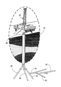
Figure 1 illustrates an overall view of multiple
wells being drilled out of a single caisson from a single
location in the method of the present invention;
Figure 2 illustrates a cross-section view of the
multiple wells within the caisson as illustrated in
Figure 1 in the method of the present invention;
Figure 3A illustrates a water injection well to
return waste water into the formation utilizing a
vertical well in the method of the present invention;
Figure 3B illustrates a water injection well
returning waste water into the formation through a use of
a horizontal well extending from the vertical well in
Figure 3A in the method of the present invention;
7
CA 02852358 2014-05-20
Figure 4 illustrates yet another embodiment of the
water injection well in Figures 3A and 3B, where there
are multiple lateral wells extending out from the
horizontal well in the method of the present invention;
Figure 5 illustrates a depiction of the drilling of
the lateral wells perpendicular to the face cleats in the
coal seam to recover maximum of methane gas from the coal
seam in the method of the present invention;
Figure 6 illustrates the single pass continuous
circulation drilling utilized in the method of the
present invention;
Figure 7 illustrates the continuous circulating
concentric casing pressure management with friction and
choke methods in the method of the present invention;
Figure 8 illustrates a wellhead for continuous
circulation in the method of the present invention;
Figure 9 illustrates a plurality of lateral wells
which have been lined with liners as the methane gas is
collected from the coal seam in the method of the present
invention;
Figure 10 illustrates an overall view of the methane
gas collection from the coal seam utilizing a plurality
of lateral wells and the water injection well returning
used water into the underground, all through the same
caisson in the method of the present invention;
Figure 11 illustrates a depiction of a plurality of
horizontal wells having been drilled parallel to the face
cleats and a plurality lateral wells having been drilled
perpendicular to the face cleats in the coal seam for
obtaining maximum collection of methane gas; and
Figure 12 illustrates a continuous circulating
concentric casing in the method of the present invention.
DETAILED DESCRIPTION OF THE PREFERRED EMBODIMENT
Figures 1 through 11 illustrate the preferred method
of the present invention, which in summary is a plurality
8
CA 02852358 2014-05-20
of wells being drilled through a single caisson from the
rig floor, at least two of the wells drilled for the
ultimate collection of methane gas from a coal seam, and a
third well drilled to return waste water used in the
process to a water collection zone beneath the surface.
Turning now to the individual Figures, as seen in
overall view in Figure 1, and in cross-section view in
Figure 2, there is illustrated in overall view in Figure 1,
a drilling rig 20 having a single caisson 22 with three
wells 24, 26, 28 within the single caisson 22. As seen,
each of the wells include a vertical well section 29, which
terminates in at least one or more horizontal wells 30,
which branch off into a plurality of lateral wells 32, for
reasons stated herein. Of the three wells depicted, two of
the wells 24, 26 are multilateral wells to produce water
and methane gas, while the third well 28 comprises an
injection well 28 that can inject waste water back into one
of the underground reservoirs.
The two producing wells 24, 26 would produce the water
and methane gas after completion, where the recovery from
these wells would be run thru a centrifuge 82 (as seen in
Figure 7) to remove the fine particles during the drilling
phase and additionally a centrifuge would be used after
completion to remove the coal fines for re-injection, while
for the third well 28, water would be re-injected back into
the earth in a water bearing zone. The configuration of the
three wells 24, 26, 28 within a single conduit or caisson
22 is important and novel since this allows the single site
to produce gas through the circulated water in wells 24,
and 26, and send waste water down into the water bearing
zone via well 28, rather than on site collection ponds,
which may be required in some jurisdictional legal
guidelines.
As further illustrated in Figures 3A and 3B, water 36
is being injected into a vertical well section 29 (Figure
9
CA 02852358 2014-05-20
3A), or into a horizontal well 30 (Figure 3B) or into a
horizontal with multiple laterals 32, as seen in Figure 4
for sending the water into water bearing zones in formation
31. Figure 4 depicts injection down the hole of produced
water or produced waste water 37 that has been run thru
solids removal equipment.
In understanding the nature of a coal seam, coal seams
contain face cleats and butt cleats. All of the face cleats
comprise cracks in the coal seam which are in a certain
direction and comprise the pathway for gas movement thru
the coal seam, while the butt cleats connect the face
cleats. In a
coal seam all major fractures, or face
cleats, are in the same direction.
Therefore, if one
drills in parallel to the face cleats, and only connects
two of them, this is the most stable direction. But, if
one drills perpendicular to the face cleats, and connects
all of the fractures, the recovery is very good, which has,
in effect, created a new mechanical induced butt cleat,
i.e., connecting one or more face cleats. Drilling from
parallel to perpendicular requires more hydrostatic
pressure, i.e. mud weight, going from stable to unstable.
Most drillers want to drill parallel to the face cleats to
avoid the instability in the well. For example, the mine
shaft in a coal mine may be mined parallel to the face
cleats, to avoid collapse of the mine shaft. However, in
coal bed drilling for methane gas, the recovery, when one
drills perpendicular to the face cleats is 10 to 20 times
more productive; therefore, the most productive direction
is to drill perpendicular.
With that in mind, turning now to Figure 5, it has
been determined that if there is a fracture in the coal
seam, referenced as face cleat fractures 50, that these
face cleat fractures 50 would all be parallel one another
in the coal seam. One would drill a vertical well, such as
well 24, and drill the horizontal well 30 parallel to the
CA 02852358 2014-05-20
fractures 50 for attaining the most stable well bore, which
means the less likely to collapse under downhole pressures.
Drilling parallel to the fractures 50 is the most stable
direction, but it is the least productive of the drilling.
One would want to be able to drill perpendicular to the
fractures 50 for maximum production of methane gas through
the lateral wells 32. As stated earlier, drilling
perpendicular to the fractures is useful because production
of methane gas is ten to twenty times greater when the
production wells are perpendicular to the fractures 50
rather than parallel to the fractures 50.
In an embodiment of the present invention, to drill
perpendicular to the face cleat fractures 50 in a stable
environment, one would provide higher hydrostatic pressure
by higher mud weight or, with water alone, having the water ,
exhibit characteristics which renders its weight or ECD
from 8.6 to 12.6 lbs/gal, for example. An embodiment of the
present invention provides the desired weight or ECD thru
creating mechanical friction, since fluid has resistance,
which creates back pressure. In another embodiment, using
fresh water, the method comprises use of chokes on surface.
For example, one would pump in 100 gallons, but only let
out 90 gallons, therefore creating back pressure. The back
pressure caused by this process would give greater weight
effect or ECD to the water, and increase sufficient
hydrostatic pressure in the well bore.
In an embodiment of the present invention, one would
use treated water free from any chemicals and bacteria. An
object of the present invention is to enable a cleaner
formation with no damage by chemicals. However, because the
perpendicular drilled wells create instability, in order to
minimize that problem, a higher bottom hole pressure is
useful, when the coal seam is pressurized down hole. As
discussed earlier, in order to minimize a coal seam from
being damaged by mud additives added to water in order to
11
CA 02852358 2014-05-20
create a greater hydrostatic pressure, in a preferred
embodiment one would drill with clear water. However, it
is difficult to obtain the proper hydrostatic pressure to
keep the well from collapsing with just water, without
increasing the hydrostatic pressure in some manner. In
coal reservoirs which are pressured, there is a need for a
process to obtain instantaneous increases of hydrostatic
pressure from 8.6 to 12.6 lbs per gallon mud or higher,
such as barite or other chemicals added to the water.
These chemicals damage the permeability in the formation,
actually holding back the pressure, and reduce the
opportunity for desorption of methane gas from the
formation. Therefore, in a preferred embodiment pure or
clear water (containing less than 4 microns of solids
drilling fluid, for example) is used, which has a weight of
8.6, but has the effect as the heavier mud, at possibly 12
lbs/gal. In a preferred embodiment of the present
invention, to address this problem, one would drill the
wells from the parallel or sub-parallel to the
perpendicular, without agents, such as chemicals, and with
use of friction or back pressure, or a combination of both,
as discussed earlier. These means, i.e. the friction or
back pressure, can increase the circulating density of the
fluid, which is only water in a preferred embodiment.
23 Turning therefore to Figures 6 through 8, these
figures show that on the surface systems may be used to
increase friction within the well or through the use of a
choke manifold, or a combination of both circulated
continuously down the concentric annulus, both of which
would cause the water to exhibit a greater hydrostatic
pressure, of a suitable magnitude, without the use of
chemical or surfactants. By creating the higher equivalent
of back pressure, through friction or a choke manifold, one
is able to drill the wells perpendicular, for greater
recovery of methane gas. That allows one to drill
12
CA 02852358 2014-05-20
perpendicular and have a higher effective bottom hole
pressure without having the bore collapse. There are no
chemical agents, such as surfactants involved, which can
cause the clay to swell and choke off the flow of gas out
of the formation.
It should be noted that as seen in Figures 6 through
8, the system, in a preferred embodiment, would be a
continuous circulating system for reducing the likelihood
of the formation collapsing under pressure, wherein the
water through either friction or the choke valve maintains
a 10 lb. per sq. inch pressure down hole, for example,
without the use of chemicals.
In Figure 6, water is pumped from pumps 70 and 72 via
line 74 to the stand pipe 76 and circulated down the
borehole. While circulating, due to the hydrostatic
pressure of the water and choking effects, for reasons
described earlier, the formation remains stable. The water
is then returned from the borehole, and after cleansing
through the shale shaker 78, de-silter 80, and decanting
centrifuge 82, the water returns to pumps 70 and 72.
In Figures 7-8, the water is being pumped from pump 70
via line 74 to stand pipe 76 returning up bore 90.
Simultaneously pumping with pump 70 from pump 72 via line
103, then down annulus 104 thru perforations 100, and
returns comingled with fluid from pump 70 up the inner
annulus 98 of the well, and goes to the rig manifold 94.
This creates both friction control of the annulus and
choking to increase the hydrostatic SOD control of bottom
hole pressure. The water is then cleansed and returns to
pumps 70 and 72. Figure 8 illustrates a view of a well head
102, with the water being pumped down an inner bore 96, and
returned up an annulus 98 where the water from pump 70 and
pump 72 are comingled creating the friction effect for
hydrostatic friction which then returns to the rig floor
for additional choking effect and separation. In a
13
CA 02852358 2014-05-20
preferred embodiment the present invention is a continuous
circulation system, if circulation stops, i.e., turn the
pumps off, this can create a loss of friction and choking,
so that the formation may collapse. Pump 72 during
connections can increase its flow to match the gallons per
minute of both pumps 70 and 72 to maintain the friction
effect. After a connection is made and flow is re-
established to pump 70, pump 72 can slow to the comingled
volume and maintain the friction effect.
As illustrated in Figure 9, at some point in time
during the process, one may wish to case the laterals 32
off. Figure 9 illustrates slotted liners 60 which have been
inserted into each of the laterals 32. This is useful to
help maintain the integrity of the laterals 32 during the
method of the invention.
In Figure 10, there is again depicted an overall view
of a drilling rig 20 with multiple wells from a single
caisson 22, where some of the laterals 32 from wells 24, 26
are collecting methane gas by continuously circulating
water into the formation, while laterals 32 from a third
well 28 are returning waste water to the water bearing
zones beneath the surface. In Figure 11, there is depicted
the vertical wells extending from the single caisson 22,
where there are a plurality of horizontal wells 30 drilled
in the same direction as the face cleat fractures 50, to
maintain stability, but where there are a plurality of
lateral wells 32 being drilled perpendicular to the
horizontal wells 30 through multiple face cleats 50 of the
coal seam, to obtain maximum methane gas recovery. In an
embodiment of the present invention, cased hole or open
hole may be used, wherein the hydrostatic pressure is
maintained through the continuous circulation of the water
through the system under friction or through a choke at the
surface, for maintaining the hydrostatic pressure of the
water sufficiently high to prevent collapse of the
14
CA 02852358 2014-05-20
formation at all times.
In an embodiment of the present invention, the novel
system for recovering methane gas from coal seams involves
a continuously circulating concentric pressure drilling
program which may be adapted to include a splitter wellhead
system for purposes of using a single borehole with three
wells, or conduits, in the single borehole, with two of the
conduits used for completing coal bed methane wells, and
the third used as a water disposal well all within a single
well caisson.
An embodiment of the present invention, involves a
process for recovering methane from coal seams through the
following steps: drilling and installing a caisson with
multiple conduits; drilling a well bore through the conduit
into a coal seam; using a continuous circulating process to
drill and complete those wells within the coal seam with
the lateral wells being perpendicular to the face cleats
of the coal seam so that the well extends through multiple
face cleats for maximum recovery of methane gas; completing
each well either open or cased hole; next, drill the second
well, and complete a series of multi-lateral wells into the
coal seam perpendicular to the face cleat fractures as
described earlier; then, in the third conduit, drill a
vertical or horizontal or multilateral well for disposing
the water produced from the other two conduits. The water
would be returned through a pumping mechanism from conduits
1 and 2, filtered for solids removal, and re-injected into
the well bore via the borehole in conduit 3. The present
invention overcomes problems in the prior art thru use of
multiple wells drilled from a single caisson in a coal bed
methane system, using friction and choking methods to
maintain the proper hydrostatic pressure of pure water, for
coal bed methane recovery in at least two of the wells, and
injecting water down hole, all within the same vertical
well bore.
CA 02852358 2014-05-20
In an embodiment of the method of the present
invention for a continuous circulating concentric casing
managed equivalent circulating density (ECD) drilling
method, the method involves a continuous circulating
concentric casing using less than conventional mud density.
Using less than conventional mud density, the well will be
stable and dynamically dead, but may be statically
underbalanced (see Figure 12). As stated earlier, in an
embodiment of the invention and in the well planning, one
would drill wells perpendicular to the face cleats of the
coal. From the
face cleat direction, there would be a
single fracture, reorientation and a single t-shaped
multiple 105 provided as seen in Figure 5.
For purposes of the below paragraph, the following
abbreviations will apply:
Equivalent Circulating Density (ECD)
Managed Pressure Drilling (MPD)
Bottom Hole Pressure (BHP)
Bottom Hole Circulating Pressure (BHCP)
Mud Weight (MW)
The MPD advantage as seen is at under conventional
drilling MPD = MW + Annulus Friction Pressure. BHP control
= only pump speed and MW change, because it is an "Open to
Atmosphere" system; whereas in Managed Pressure Drilling
(MPD), the MPD = MW + Annulus Friction Pressure +
Backpressure. BHP
control = pump speed, MW change and
application of back pressure, because it is an enclosed,
pressured system.
In the continuous circulating concentric casing
pressure management, there is provided an adaptive drilling
process used to precisely control the annular pressure
profile throughout the wellbore. The objectives are to
ascertain the downhole pressure environment limits and to
manage the annular hydraulic pressure profile accordingly.
It is an objective of the system to manage BHP from a
16
CA 02852358 2014-05-20
specific gravity of 1 to 1.8 utilizing clean, less than 4
microns of solids, for example, in the drilling fluid. The
drilling fluid may be comprised of produced water from
other field wells. Any influx incidental to the operation
would be safely contained using an appropriate process.
Figure 12 illustrates a continuous circulating
concentric casing where using less than conventional mud
density, the well will be stable and dynamically dead, but
may be statically underbalanced.
The following is a list of parts and materials
suitable for use in the present invention:
PARTS LIST:
PART NUMBER DESCRIPTION
drilling rig
15 22 caisson
24, 26, 28 wells
29 vertical well section
horizontal wells
31 formation
20 32 lateral wells
36 water
37 produced waste water
50 face cleat fractures
60 slotted liners
25 70, 72 pumps
74 line
76 stand pipe
78 shale shaker
80 de-silter
30 82 centrifuge
90 bore
94 rig manifold
96 inner bore
98 annulus
100 perforations
17
CA 02852358 2014-05-20
102 well head
103 line from pump 72
104 inner annulus
105 t-shaped multiple
All measurements disclosed herein are at standard
temperature and pressure, at sea level on Earth, unless
indicated otherwise.
The foregoing embodiments are presented by way of
example only; the scope of the present invention is to be
limited only by the following claims.
18