Note: Descriptions are shown in the official language in which they were submitted.
CA 02852439 2014-05-28
SYSTEMS AND METHODS FOR RADIOIVIE'TRICALLY MEASURING
TEMPERATURE AND DETECTING TISSUE CONTACT PRIOR TO AND DURING
TISSUE ABLATION
Field of the Invention
(0001]
This application generally relates to systems and methods for measuring
temperature and detecting tissue contact prior to and during tissue ablation.
Background of the Invention
[0002] Tissue
ablation may be used to treat a variety of clinical disorders. For
example, tissue ablation may be used to treat cardiac arrhythmias by
destroying aberrant
pathways that would otherwise conduct abnormal electrical signals to the heart
muscle,
[0003]
Several ablation techniques have been developed, including cryoablation,
microwave ablation, radio frequency (RF) ablation, and high frequency
ultrasound ablation.
For cardiac applications, such techniques are typically performed by a
clinician who
introduces a catheter having an ablative tip to the endocardium via the venous
vasculature,
positions the ablative tip adjacent to what the clinician believes to be an
appropriate region of
the endocardium based on tactile feedback, mapping electrocardiogram (ECG)
signals,
anatomy, and/or fluoroscopic imaging, actuates flow of an irrigant to cool the
surface of the
selected region, and then actuates the ablative tip for a period of time and
at a power believed
sufficient to destroy tissue in the selected region.
(00041
Although commercially available ablative tips may include thermocouples
for providing temperature feedback via a digital display, such thermocouples
typically do not
provide meaningful temperature feedback during irrigated ablation. For
example, the
thermocouple only measures surface temperature, whereas the heating or cooling
of the tissue
that results in tissue ablation may occur at some depth below the tissue
surface, Moreover, for
procedures in which the surface of the tissue is cooled with an irrigant, the
thermocouple will
measure the temperature of the irrigant, thus further obscuring any useful
information about
the temperature of the tissue, particularly at depth. As such, the clinician
has no useful
-1-
CA 02852439 2014-05-28
feedback regarding the temperature of the tissue as it is being ablated or
whether the time
period of the ablation is sufficient.
[0005]
Moreover, during an ablation procedure it is important that the clinician
position the ablative tip directly against the cardiac surface (e.g., makes
good contact) before
activating the ablation energy source and attempting to ablate the tissue. If
the clinician does
not have good tissue contact, ablation energy may heat the blood instead of
the tissue, leading
to the formation of an edema, e.g., a fluid-filled pocket or blister on the
tissue surface. Such
an edema may inhibit adequate destruction of aberrant nerve pathways in the
tissue. For
example, edemas may physically interfere with the clinician's ability to
contact a desired
region of tissue with the ablative tip, and thus may interfere with
destruction of a desired
nerve pathway. Additionally, partial lesions or lesions in undesired locations
have been found
after the clinician completes the procedure and the edema dissipates.
Formation of such partial
or undesired lesions are thought to be caused by reduced contact between the
ablative tip and
the tissue, resulting in a tissue temperature insufficient to cause tissue
necrosis. Edemas and
partially formed lesions also may make it more difficult to create an
effective lesion in the
future, for example during a touch-up ablation within the same procedure or
later on during a
secondary procedure.
[0006]
Accordingly, it may only be revealed after the procedure is completed ¨ for
example, if the patient continues to experience cardiac arrhythmias ¨ that the
targeted aberrant
pathway was not adequately interrupted. In such a circumstance, the clinician
may not know
whether the procedure failed because the incorrect region of tissue was
ablated, because the
ablative tip was not actuated for a sufficient period of time to destroy the
aberrant pathway,
because the ablative tip was not touching or not sufficiently touching the
tissue, because the
power of the ablative energy was insufficient, or some combination of the
above. Upon
repeating the ablation procedure so as to again attempt to treat the
arrhythmia, the clinician
may have as little feedback as during the first procedure, and thus
potentially may again fail to
destroy the aberrant pathway. Additionally, there may be some risk that the
clinician would re-
treat a previously ablated region of the endocardium and not only ablate the
conduction
pathway, but damage adjacent tissues.
-2-
CA 02852439 2014-05-28
[0007] In some circumstances, to avoid having to repeat the
ablation procedure as
such, the clinician may ablate a series of regions of the endocardium along
which the aberrant
pathway is believed to lie, so as to improve the chance of interrupting
conduction along that
pathway. However, there is again insufficient feedback to assist the clinician
in determining
whether any of those ablated regions are sufficiently destroyed.
[0008] U.S. Pa. No. 4,190,053 to Sterzer describes a hyperthermia
treatment
apparatus in which a microwave source is used to deposit energy in living
tissue to effect
hyperthermia. The apparatus includes a radiometer for measuring temperature at
depth within
the tissue, and includes a controller that feeds back a control signal from
the radiometer,
corresponding to the measured temperature, to control the application of
energy from the
microwave source, The apparatus alternates between delivering microwave energy
from the
microwave source and measuring the radiant energy with the radiometer to
measure the
temperature. As a consequence of this time division multiplexing of energy
application and
temperature measurement, temperature values reported by the radiometer are not
simultaneous
with energy delivery.
[0009] U.S. Pat. No. 7,769,469 to Carr et al. describes an
integrated heating and
sensing catheter apparatus for treating arrhyfhmias, tumors and the like,
having a diplexer that
permits near simultaneous heating and temperature measurement. This patent too
describes
that temperature measured by the radiometer may be used to control the
application of energy,
e.g., to maintain a selected heating profile.
[0010] Despite the promise of precise temperature measurement
sensitivity and
control offered by the use of radiometry, there have been few successful
commercial medical
applications of this technology. One drawback of previously-known systems has
been an
inability to obtain highly reproducible results due to slight variations in
the construction of the
microwave antenna used in the radiometer, which can lead to significant
differences in
measured temperature from one catheter to another. Problems also have arisen
with respect to
orienting the radiometer antenna on the catheter to adequately capture the
radiant energy
emitted by the tissue, and with respect to shielding high frequency microwave
components in
the surgical environment so as to prevent interference between the radiometer
components and
other devices in the surgical field.
-3-
CA 02852439 2014-05-28
100111
Acceptance of microwave-based hyperthermia treatments and temperature
measurement techniques also has been impeded by the capital costs associated
with
implementing radiometric temperature control schemes. Radiofreq-uency ablation
techniques
have developed a substantial following in the medical community, even though
such systems
can have severe limitations, such as the inability to accurately measure
tissue temperature at
depth, e.g., where irrigation is employed. However, the widespread acceptance
of RF ablation
systems, extensive knowledge base of the medical community with such systems,
and the
significant cost required to changeover to, and train for, newer technologies
has dramatically
retarded the widespread adoption of radiometry.
100121 In view of
the foregoing, it would be desirable to provide apparatus and
methods that permit radiometric measurement of temperature at depth in tissue,
and permit
use of such measurements to control the application of ablation energy in an
ablation
treatment, e.g., a hyperthermia or hypothermia treatment, particularly in
which contact
between the ablative tip and the tissue readily may be assessed.
[0013] It further
would be desirable to provide apparatus and methods that employ
microwave radiometer components that can be readily constructed and calibrated
to provide a
high degree of measurement reproducibility and reliability.
[00141 It
also would be desirable to provide apparatus and methods that permit
radiometric temperature measurement and control techniques to be introduced in
a manner
that is readily accessible to clinicians trained in the use of previously-
known RF ablation
catheters, with a minimum of retraining, and that provide readily
understandable signals to the
clinicians as to whether the ablative tip is in contact with tissue.
[0015] It
still further would be desirable to provide apparatus and methods that
permit radiometric temperature measurement and control techniques to be
readily employed
with previously-known RF electrosurgical generators, thereby reducing the
capital costs
needed to implement such new techniques.
Summary
100161 In
view of the foregoing, it would be desirable to provide apparatus and
methods for treating living tissue that employs a radiometer for temperature
measurement and
-4-
CA 02852439 2014-05-28
control. In accordance with one aspect of the disclosure, systems and methods
are provided
for radiometrically measuring temperature and detecting tissue contact prior
to and during RF
ablation, i.e., calculating temperature and detecting tissue contact based on
signal(s) from a
radiometer. Unlike standard thermocouple techniques used in existing
commercial ablation
systems, a radiometer may provide useful information about tissue temperature
at depth ¨
where the tissue ablation occurs ¨ and thus provide feedback to the clinician
about the extent
of tissue damage as the clinician ablates a selected region of the tissue.
Additionally, the
radiometer may provide useful information about whether an ablative tip is in
contact with
tissue, and thus provide feedback to assist the clinician in properly
contacting and ablating the
tissue.
[0017] In
one embodiment, the present invention comprises an interface module
(system) that may be coupled to a previously-knovvn commercially available
ablation energy
generator, e.g., an electrosurgical generator, thereby enabling radiometric
techniques to be
employed with reduced. capital outlay. In this manner, the conventional
electrosurgical
generator can be used to supply ablative energy to an "integrated catheter
tip" (ICT) that
includes an ablative tip, a thermocouple, and a radiometer for detecting the
volumetric
temperature of tissue subjected to ablation. The interface module is
configured to be coupled
between the conventional electrosurgical generator and the ICT, and to
coordinate signals
therebetween. The interface module thereby provides the electrosurgical
generator with the
information required for operation, transmits ablative energy to the ICT under
the control of
the clinician, displays via a temperature display the temperature at depth of
tissue as it is being
ablated, and outputs a visible or audible indication of tissue contact for use
by the clinician.
The displayed temperature and determination of tissue contact may be
calculated based on
signal(s) measured by the radiometer using algorithms such as discussed
further below,
[0018] In an
exemplary embodiment, the interface module includes a first
input/output (I/0) port that is configured to receive a digital radiometer
signal and a digital
thermocouple signal from the ICT, and a second I/0 port that is configured to
receive ablative
energy from the electrosurgical generator. The interface module also includes
a processor, a
patient relay in communication with the processor and the first and second I/0
ports, and a
persistent computer-readable medium. The computer-readable medium stores
operation
-5-
CA 02852439 2014-05-28
parameters for the radiometer and the thermocouple, as well as instructions
for the processor
to use in coordinating operation of the ICT and the electro surgical
generator,
[0019] The
computer-readable medium preferably stores instructions that cause the
processor to execute the step of calculating a temperature adjacent to the ICT
based on the
digital radiometer signal, the digital thermocouple signal, and the operation
parameters. This
temperature is expected to provide significantly more accurate information
about lesion
quality and temperature at depth in the tissue than would a temperature based
solely on a
thermocouple readout. The computer-readable medium may further store
instructions for
causing the processor to cause the temperature display to display the
calculated temperature,
for example so that the clinician may control the time period for ablation
responsive to the
displayed temperature. The computer-readable medium may further store
instructions for
causing the processor to close the patient relay, such that the patient relay
passes ablative
energy received on the second 1/0 port, from the electrosurgical generator, to
the first I/0 port,
to the ICT. Note that the instructions may cause the processor to maintain the
patient relay in a
normally closed state, and to open the patient relay upon detection of unsafe
conditions.
[0020] The
computer-readable medium preferably also stores instructions that
cause the processor to execute the step of determining whether the ICT is in
contact with
tissue, based on the digital radiometer signal. For example, because blood and
tissue have
different dielectric constants, the digital radiometer signal may change when
the ICT is
brought into or out of contact with the tissue, The instructions may cause the
processor to
monitor the digital radiometer signal for changes. Any such changes may be
compared to a
predetemiined threshold value (also stored on the computer-readable medium).
If the change
is determined to be greater than the threshold value, then the processor
outputs a signal to an
output device that, responsive to the signal, indicates whether the ICT is in
contact with tissue.
The output device may be, for example, a visual display device that visually
represents the
tissue contact, e.g,, a light that illuminates when there is tissue contact,
or an audio device that
audibly represents the tissue contact, e.g., a speaker that generates a tone
when there is tissue
contact. Preferably, the processor determines whether the ICT is in contact
with the tissue
before passing ablation energy to the ICT,
-6-
CA 02852439 2014-05-28
[0020A] In
one illustrative embodiment, a system for facilitating detection of
contact with targeted tissue of a subject includes a catheter including a
radiofrequency
electrode and a radiometer, and a processor. The processor is configured to
receive a signal
from the radiometer and to provide an output indicative of contact between the
radiofrequency
electrode and targeted tissue of the subject based upon, at least in part,
tissue properties
determined from the signal received from the radiometer,
[0020B] In
another illustrative embodiment, a system for facilitating detection of
contact with targeted tissue of a subject includes a processor which is
configured to receive a
signal from a radiometer positioned at a tip along a distal end of a catheter,
and to provide an
output indicative of contact between the tip of the catheter and targeted
tissue of a subject
based upon, at least in part, tissue properties determined from the signal
received from the
radiometer,
[0920C1 In
another illustrative embodiment, a system for facilitating detection of
contact with targeted tissue of a subject includes a processor, which is
configured to receive a
signal from a radiometer carried by a medical instrument and to provide an
output indicative
of contact between a portion of the medical instrument and targeted tissue of
a subject based
upon, at least in part, tissue properties determined from the signal received
from the
radiometer.
[0020D] In
another illustrative embodiment, a method of determining contact
between a medical instrument and tissue of a subject includes determining
whether a
radiofrequency electrode positioned at a distal end of a catheter is in
contact with tissue based
on tissue properties determined from a signal generated by a radiometer
positioned at the
distal end of the catheter, The method further includes causing energy to be
delivered to the
tissue by activating the radiofrequency electrode after determining that the
radiofrequency
electrode is in contact with the tissue.
[0020E] In
another illustrative embodiment, a method of determining contact
between a medical instrument and tissue of a subject includes determining
whether an energy
delivery member of a medical instrument is in contact with tissue based on
tissue properties
determined from a signal generated by a radiometer positioned at a distal end
of the medical
instrument. The method further includes causing energy to be delivered to the
tissue by
-7-
CA 02852439 2014-05-28
activating the energy delivery member after determining that the energy
delivery member is in
contact with the tissue.
[0020F1 In
another illustrative embodiment, a method of determining contact
between a medical instrument and tissue of a subject includes determining
whether a medical
instrument is in contact with tissue based on tissue properties determined
from a signal
generated by a radiometer carried by the medical instrument, and generating an
output
indicating that a portion of the medical instrument is in contact with the
tissue.
Brief Description of Drawings
[0021] FIG. lA is a
schematic illustration of a first embodiment of an arrangement
including an interface module with tissue contact indicator, including a
display of the front
and back panels of, and exemplary connections between, the interface module, a
previously
known ablation energy generator, e.g., electrosurgical generator, and an
integrated catheter tip
(ICT).
[0022] FIG. 1B is a
schematic illustrating exemplary connections to and from the
interface module of FIG: 1A, as well as connections among other components
that may be
used with the interface module.
[0023]
FIG. 2A is a schematic illustrating internal components of the interface
module of FIGS. 1A-1B.
10024] FIG. 2B
schematically illustrates additional internal components of the
interface module of FIG. 2A, as well as selected connections to and from the
interface
module.
[00251
FIG. 3A illustrates steps in a method of using the interface module of
FIGS. 1A-2B during tissue ablation.
10026] FIG. 3B
illustrates steps in a method of calculating radiometric temperature
using digital signals from a radiometer and a thermocouple and operation
parameters.
[0027]
FIG. 3C illustrates steps in a method of controlling an ablation procedure
using a temperature calculated based on signal(s) from a radiometer using the
interface
module of FIGS. 1A-2B.
-8-
CA 02852439 2014-05-28
(0028]
FIG. 4A illustrates data obtained during an exemplary tissue contact
measurement procedure performed using the interface module of FIGS, 1A-2B.
[0029]
FIGS. 4B-4E illustrate data obtained during exemplary ablation procedures
performed using the interface module of FIGS. 1A-2B.
[0030] FIG. SA
illustrates a plan view of an exemplary patient interface module
(PIM) associated with an integrated catheter tip (ICT) for use with the
interface module of
FIGS. 1A-2B.
[0031]
FIG. 5B schematically illustrates selected internal components of the PIM
of FIG. 5A, according to some embodiments of the present invention.
[0032] FIGS. 6A-6B
respectively illustrate perspective and exploded views of an
exemplary integrated catheter tip (ICI) for use with the interface module of
FIGS. IA-2B and
the PIM of FIGS. 5A-5B, according to some embodiments of the present
invention.
Detailed Description
[0033] Embodiments
of the present invention provide systems and methods for
radiometrically measuring temperature and detecting tissue contact prior to
and during
ablation, in particular cardiac ablation. As noted above, commercially
available systems for
cardiac ablation may include thermocouples for measuring temperature, but such
thermocouples may not adequately provide the clinician with information about
tissue
temperature or tissue contact, Thus, the clinician may need to make an
"educated guess" about
whether an ablative tip is in contact with tissue, as well as whether a given
region of tissue has
been sufficiently ablated to achieve the desired effect. By comparison,
calculating a
temperature based on signal(s) from a radiometer is expected to provide
accurate information
to the clinician about the temperature of tissue at depth, even during an
irrigated procedure.
Moreover, the signal(s) from the radiometer may be used to determine whether
the ablative tip
is in sufficient contact with tissue before attempting to ablate the tissue,
so as to reduce the
likelihood of forming edemas such as described above and improve the
likelihood of creating
effective transmural lesions. The present invention provides a "retrofit"
solution that includes
an interface module that works with existing, commercially available ablation
energy
generators, such as electrosurgical generators. In accordance with one
embodiment of the
-9-
CA 02852439 2014-05-28
present invention, the interface module displays a tissue temperature and
provides an
indication of tissue contact based on signal(s) measured by a radiometer, that
a clinician may
use to perform ablation procedures with significantly better accuracy than can
be achieved
using only a thermocouple for temperature measurement.
00341 First, high
level overviews of the interface module, including tissue contact
indicator, and connections thereto are provided. Then, further detail on the
internal
components of the interface module, and exemplary methods of calculating
radiometric
temperature, determining tissue contact, and controlling an ablation procedure
based on same,
are provided. Data obtained during experimental procedures also is presented.
Lastly, further
detail on components that may be used with the interface module is provided.
[0035]
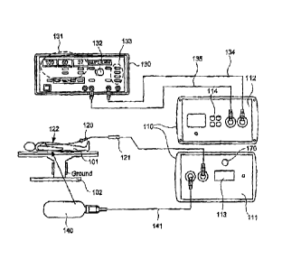
FIG. 1A illustrates plan views of front panel 111, back panel 112, and
connections to and from exemplary interface module 110, constructed in
accordance with the
principles of the present invention. As illustrated in FIG. 1A, front panel
111 of interface
module 110 may be connected to a catheter 120 that includes patient interface
module (NM)
121 and integrated catheter tip (ICT) 122. Catheter 120 optionally is
steerable, or may be non-
steerable and used in conjunction with a robotic positioning system or a third-
party steerable
sheath (not shown). ICT 122 is positioned by a clinician (optionally with
mechanical
assistance such as noted above), during a procedure, within subject 101 lying
on grounded
table 102. ICT 122 may include, among other things, an ablative tip, a
thermocouple, and a
radiometer for detecting the volumetric temperature of tissue subjected to
ablation. The ICT
122 optionally includes one or more irrigation ports, which in one embodiment
may be
connected directly to a commercially available irrigant pump.
[0036] In
embodiments in which the ablation energy is radiofrequency (RF)
energy, the ablative tip may include an irrigated ablation electrode, such as
described in
greater detail below with reference to FIGS. 6A-6B. ICI' 122 further may
include one or more
electrocardiogram (ECG) electrodes for use in monitoring electrical activity
of the heart of
subject 101. Interface module 110 receives signals from the thermocouple,
radiometer, and
optional ECG electrodes of ICT 122 via PIM 121. Interface module 110 provides
to ICT 122,
via PIM 121, power for the operation of the PIM and the sensors (thermocouple,
radiometer,
and ECG electrodes), and ablation energy to be applied to subject 101 via the
ablative tip.
-10-
CA 02852439 2014-05-28
[0031 Front panel 111
includes tissue contact indicator 170, which is an output
device configured to indicate whether ICT 122 is in contact with tissue, e.g.,
which interface
module 110 determines based on signal(s) from the radiometer as described in
greater detail
below. Tissue contact indicator 170 may include a visual display device that
visually
represents interface module 110's determination of whether ICT 122 is in
contact with tissue.
For example, tissue contact indicator 170 may include a light that illuminates
when interface
module 110 determines that ICT 122 is in contact with tissue, and is dark when
interface
module 110 determines that ICT 122 is out of contact with tissue.
Alternatively, tissue contact
indicator 170 may be an audio device that audibly represents interface module
110's
determination of whether ICT 122 is in contact with tissue. For example,
tissue contact
indicator 170 may include a speaker that generates a tone when interface
module 110
determines that ICT 122 is in contact with tissue, and is silent when
interface module 110
determines that ICT 122 is out of contact with tissue. Tissue contact
indicator 170 may
continuously generate a tone throughout the duration of the contact, and cease
generating the
tone when contact is lost, so as to facilitate the clinician's ability to
determine whether tissue
contact has been lost. Alternatively, tissue contact indicator 170 may
generate a brief tone at a
first frequency when contact is made, and may generate a second tone at a
second frequency
when contact is lost. Optionally, tissue contact indicator 170 includes a
visual display device
and an audio device for providing the clinician with both visible and audible
indications of
tissue contact.
[0038j Back panel 112 of
interface module 110 may be connected via connection
cable 135 to a commercially available previously-known ablation energy
generator 130, for
example an electro surgical generator 130, such as a Stockert EP-Shuttle 100
Generator
(Stockert GmbH, Freiburg Germany) or Stockert 70 RE Generator (13iosense
Webster,
Diamond Bar, California). In embodiments where the electrosurgical generator
130 is a
Stockert EP-Shuttle or 70 RF Generator, generator 130 includes display device
131 for
displaying temperature and the impedance and time associated with application
of a dose of
RE ablation energy; power control knob 132 for allowing a clinician to
manually adjust the
power of RE ablative energy delivered to subject 101; and start/stop/mode
input 133 for
allowing a clinician to initiate or terminate the delivery of RE ablation
energy. Start/stop/mode
-11-
CA 02852439 2014-05-28
input 133 also may be configured to control the mode of energy delivery, e.g.,
whether the
energy is to be cut off after a given period of time.
[00391
Although generator 130 may be configured to display temperature on
display device 131, that temperature is based on readings from a standard
thermocouple. As
noted above, however, that reported temperature may be inaccurate while
irrigant and ablative
energy are being applied to tissue. Interface module 110 provides to generator
130, via
connection cable 135, a thermocouple signal for use in displaying such a
temperature, and
signals from the ECG electrodes; and provides via indifferent electrode cable
134 a pass-
through connection to indifferent electrode 140. Interface module 110 receives
from generator
130, via connection cable 135, RF ablation energy that module 110 controllably
provides to
ICT 122 for use in ablating tissue of subject 101.
[00401 As
will be familiar to those skilled in the art, for a monopolar RF ablation
procedure, a clinician may position an indifferent electrode (M) 140 on the
back of subject
101 so as to provide a voltage differential that enables transmission of RF
energy into the
tissue of the subject. In the illustrated embodiment, M 140 is connected to
interface module
110 via first indifferent electrode cable 141. Interface module 110 passes
through the IE signal
to second indifferent electrode cable 134, which is connected to an
indifferent electrode input
port on electrosurgical generator 130. Alternatively, M 140 may be connected
directly to that
port of the electrosurgical generator. 130 via appropriate cabling (not
shown).
[0041] It should be
understood that electrosurgical generators other than the
Stockert EP-Shuttle or 70 RF Generator suitably may be used, e.g., other makes
or models of
RF electrosurgical generators. Alternatively, generators that produce other
types of ablation
energy, such as microwave generators, cryosurgical sources, or high frequency
ultrasound
generators, may be used. Ablation energy generator 130 need not necessarily be
commercially
available, although as noted above it may be convenient to use one that is. It
should also be
appreciated that the connections described herein may be provided on any
desired face or
panel of interface module 110, and that the functionalities of different
connectors and
input/output (I/O) ports may be combined or otherwise suitably modified,
[0042]
Front panel 111 of interface module 110 includes temperature display 113,
e.g., a digital two or three-digit display device configured to display a
temperature calculated
-12-
CA 02852439 2014-05-28
by a processor internal to interface module 110, e.g., as described in greater
detail below with
reference to FIGS. 2A-2B and 3A. Other types of temperature displays, such
multicolor liquid
crystal displays (LCDs), alternatively may be used. In one embodiment, the
functionalities of
temperature display 113 and tissue contact indicator 170 are provided by a
single display
device configured both to display temperature and to provide an indication of
interface
module 110's determination of whether ICT 122 is in contact with tissue, For
example, the
background of temperature display 113 may be configured to change from one
color to
another (e.g., from red to green) when interface module 110 determines that
ICT 122 is in
contact with tissue, In such an embodiment, a separate, audible tissue contact
indicator 170
such as described above optionally may be provided as well. Front panel 111
also includes
connectors (not labeled) through which interface module 110 is connected to
ICT 122 via NM
121, and to 1E 140 via indifferent electrode cable 141.
[0043]
Back panel 112 of interface module 110 includes connectors (not labeled)
through which interface module 110 is connected to electrosurgical generator
130, via
indifferent electrode cable 134 and connection cable 135. Back panel 112 of
interface module
110 also includes data ports 114 configured to output one or more signals to a
suitably
programmed personal computer or other remote device, for example an EP
monitoring/recording system such as the LABSYSTEM.Im PRO EP Recording System
(C.R.
Bard, Inc., Lowell, Mass.). Such signals may, for example, include signals
generated by the
thermocouple, radiometer, and/or ECG electrodes of the ICT, the tissue
temperature
calculated by interface module 110, and the like.
[00441
Referring now to FIG_ 1B, exemplary connections to and from interface
module 110 of FIG. 1A, as well as connections among other components, are
described. In
FIG. 1B, interface module 110 is in operable communication with catheter 120
having a
patient interface module (PIM) 121 and an integrated catheter tip (ICT) 122
that includes a
radiometer, ablative tip, a thermocouple (TC), and optionally also includes
ECG electrodes
and/or irrigation ports(s). Interface module 110 is also in operable
communication with
electrosurgical generator 130 and indifferent electrode 140.
[0045]
Electro surgical generator 130 optionally is in operable communication with
electrophysiology (EP) monitoring/recording system 160 via appropriate cabling
161, or
-13-
CA 02852439 2014-05-28
alternatively via data ports 114 of interface module 110 and appropriate
cabling (not shown).
EP monitoring/recording system 160 may include, for example, various monitors,
processors,
and the like that display pertinent information about an ablation procedure to
a clinician, such
as the subject's heart rate and blood pressure, the temperature recorded by
the thermocouple
on the catheter tip, the ablation power and time period over which it is
applied, fluoroscopic
images, and the like. EP monitoring/recording systems are commercially
available, e.g., the
MEDELEC.Tm Synergy T-EP¨EIVIG/EP Monitoring System (CareFusion, San Diego,
Calif.),
or the LABSYSTEM.Tm PRO EP Recording System (CR. Bard, Inc., Lowell, Mass.).
[0046] If
ICT 122 includes irrigation port(s), then one convenient means of
providing irrigant to such ports is irrigation pump 140 associated with
electrosurgical
generator 130, which pump is in operable communication with the generator and
in fluidic
communication with the ICT 122 via connector 151. For example, the Stockert 70
RF
Generator is designed for use with a CoolFlowTM Irrigation pump, also
manufactured by
Biosense Webster. Specifically, the Stockert 70 RF Generator and the CoolFlow.
TM pump may
be connected to one another by a commercially available interface cable, so as
to operate as an
integrated system that works in substantially the same way as it would with a
standard,
commercially available catheter tip. For example, prior to positioning ICT 122
in the body, the
clinician instructs the pump to provide a low flow rate of irrigant to the
ICT, as it would to a
standard catheter tip; the ICT is then positioned in the body. Then, when the
clinician presses
the "start" button on the face of generator 130, the generator may instruct
pump 150 to
provide a high flow rate of irrigant for a predetermined period (e.g., 5
seconds) before
providing RF ablation energy, again as it would for a standard catheter tip.
After the RF
ablation energy application is terminated, then pump 150 returns to a low flow
rate until the
clinician removes the ICT 122 from the body and manually turns off the pump.
100471 Referring now
to FIGS. 2A-2B, further details of internal components of
interface module 110 of FIGS. 1A-1B are provided.
[00481
FIG, 2A schematically illustrates internal components of one embodiment
of interface module 110. Interface module 110 includes fast, second, third,
and fourth ports
201-204 by which it communicates with external components. Specifically, first
port 201 is an
input/output (I/O) port configured to be connected to catheter 120 via PIM
121, as illustrated
-14-
CA 02852439 2014-05-28
in FIG. 1A. Port 201 receives as input from catheter 120 digital radiometer
and digital
thermocouple (TC) signals, and optionally ECG signals, generated by ICT 122,
and provides
as output to catheter 120 RF ablation energy, as well as power for circuitry
within the ICT 122
and the PIM 121. Second port 202 is also an 1/0 port, configured to be
connected to
electrosurgical generator 130 via connection cable 135 illustrated in FIG. 1A,
and receives as
input from generator 130 RF ablation energy, and provides as output to
generator 130 a
reconstituted analog thermocouple (TC) signal and raw ECG signal(s). Third
port 203 is an
input port configured to be connected to indifferent electrode (1E) 140 via
indifferent electrode
cable 134 illustrated in FIG. 1A, and fourth port 204 is an output port
configured to be
connected to generator 130 via indifferent electrode cable 141 illustrated in
FIG. 1A. As
shown in FIG. 2A, interface module 110 acts as a pass-through for the IE
signal from 1E, 140
to generator 130, and simply receives TE signal on third port 203 and provides
the 1E signal to
generator 130 on fourth port 204.
[00491
Interface module 110 also includes processor 210 coupled to non-volatile
(persistent) computer-readable memory 230, user interface 280, load relay 260,
and patient
relay 250, Memory 230 stores programming that causes processor 210 to perform
steps
described further below with respect to FIGS. 3A-.3C, thereby controlling the
functionality of
interface module 110. Memory 230 also stores parameters used by processor 210.
For
example, memory 230 may store a set of operation parameters 231 for the
thermocouple and
radiometer, as well as a temperature calculation module 233, that processor
210 uses to
calculate the radiometric temperature based on the digital TC and radiometer
signals received
on first I/O port 201, as described in greater detail below with respect to
FIG. 3B. The
operation parameters 231 may be obtained through calibration, or may be fixed.
Memoiy 230
also stores a set of safety parameters 232 that processor 210 uses to maintain
safe conditions
during an ablation procedure, as described further below with respect to FIG.
3C. Memory
230 further stores decision module 234 that processor 210 uses to control the
opening and
closing of patient relay 250 and load relay 260 based on its determinations of
temperature and
safety conditions, as described further below with reference to FIGS. 3A-3C.
When closed,
patient relay 250 passes ablative energy from the second 1/0 port 202 to the
first I/O port 201.
When closed, load relay 260 returns ablative energy to the IE 140 via dummy
load D (resistor,
-15-
CA 02852439 2014-05-28
e.g., of 120.0MEGA. resistance) and fourth I/O port 204. Memory 230 further
stores
predetermined threshold 235 value and tissue contact module 236 that processor
210 uses to
determine whether ICT 122 is in contact with tissue, and to provide output
indicative of such
contact to the clinician, such as described further below with reference to
FIG. 3A.
[0050] As
illustrated in FIG. 2A, interface module 110 further includes user
interface 280 by which a user may receive information about the temperature
adjacent ICT
122 as calculated by processor 210, as well as other potentially useful
information. In the
illustrated embodiment, user interface 280 includes digital temperature
display 113, which
displays the instantaneous temperature calculated by processor 210. In other
embodiments
(not shown), display 113 may be an LCD device that, in addition to displaying
the
instantaneous temperature calculated by processor 210, also graphically
display changes in the
temperature over time for use by the clinician during the ablation procedure.
User interface
280 further may include data ports 114, which may be connected to a computer
or EP
monitoring/recording system by appropriate cabling as noted above, and which
may output
digital or analog signals being received or generated by interface module 110,
e.g., radiometer
signal(s), a thermocouple signal, and/or the temperature calculated by
processor 210.
Preferably, user interface 280 also includes tissue contact indicator 170,
which is configured
display the processor 210s determination as to whether ICT 122 is in contact
with tissue
based on predetermined threshold value 235 and tissue contact module 236
stored in memory
230, e.g., as described in further detail below with reference to FIG. 3A.
[0051] So
as to inhibit potential degradations in the performance of processor 210,
memory 230, or user interface 280 resulting from electrical contact with RF
energy, interface
module 110 may include opto-electronics 299 that communicate information to
and from
processor 210, but that substantially inhibit transmission of RP energy to
processor 210,
memory 230, or user interface 280. This isolation is designated by the dashed
line in FIG. 2A.
For example, opto-electronics 299 may include circuitry that is in operable
communication
with first 1/0 port 201 so as to receive the digital TC and radiometer signals
from first 1/0 port
201, and that converts such digital signals into optical digital signals. Opto-
electronics 299
also may include an optical transmitter in operable communication with such
circuity, that
transmits those optical digital signals to processor 210 through free space.
Opto-electronics
-16-
CA 02852439 2014-05-28
299 further may include an optical receiver in operable communication with
processor 210,
that receives such optical digital signals, and circuitry that converts the
optical digital signals
into digital signals for use by processor 210. The opto-electronic circuitry
in communication
with the processor also may be in operable communication with a second optical
transmitter,
and may receive signals from processor 210 to be transmitted across free space
to an optical
receiver in communication with the circuitry that receives and processes the
digital TC and
radiometer signals. For example, processor 210 may transmit to such circuitry,
via an optical
signal, a signal that causes the circuitry to generate an analog version of
the TC signal and to
provide that analog signal to the second I/O port. Because opto-electronic
circuitry,
transmitters, and receivers are known in the art, its specific components are
not illustrated in
FIG. 2A.
[00521
With respect to FIG. 2B, additional internal components of interface
module 110 of FIG. 2A are described, as well as selected connections to and
from the
interface module. FIG, 2B is an exemplary schematic for a grounding and power
supply
scheme suitable for using interface module 110 with an RF electrosurgical
generator, e.g., a
Stocked EP-Shuttle or 70 RF Generator. Other grounding and power supply
schemes suitably
may be used with other types, makes, or models of electrosurgical generators,
as will be
appreciated by those skilled in the art.
10053] As
illustrated in FIG. 2B, interface module 110 includes isolated main
power supply 205 that may be connected to standard three-prong A/C power
outlet 1, which is
grounded to mains ground G. Interface module 110 also includes several
internal grounds,
designated A, B, C, and I. Internal ground A is coupled to the external mains
ground 0 via a
relatively small capacitance capacitor (e.g., a 10 pF capacitor) and a
relatively high resistance
resistor (e.g., a 20 NB/resistor) that substantially prevents internal ground
A from floating.
Internal ground B is coupled to internal ground A via a low resistance pathway
(e.g., a
pathway or resistor(s) providing less than 10000 resistance, e.g., about 0S-2
resistance).
Similarly, internal ground C is coupled to internal ground B via another low
resistance
pathway. Internal ground I is an isolated ground that is coupled to internal
ground C via a
relatively small capacitance capacitor (e.g., a 10 pF capacitor) and a
relatively high resistance
resistor (e.g., a 20 MO resistor) that substantially prevents isolated ground
I from floating.
-17-
CA 02852439 2014-05-28
[0054]
Isolated main power supply 205 is coupled to internal ground A via a low
resistance pathway. Isolated main power supply 205 is also coupled to, and
provides power
(e.g., 12V) to, one or more internal isolated power supplies that in turn
provide power to
components internal to interface module 110. Such components include, but are
not limited to
components illustrated in FIG. 2A. For example, interface module 110 may
include one or
more isolated power supplies 220 that provide power (e.g., 4V) to processor
210, memory
230, and analog circuitry 240. Analog circuitry 240 may include components of
user interface
280, including temperature display 113 and circuitry that appropriately
prepares signals for
output on data ports 114. Data ports 114, as well as analog circuitry 240, are
coupled to
internal ground B via low resistance pathways, while processor and memory 210,
230 are
coupled to internal ground C via low resistance pathways. Interface module
also may include
one or more isolated power supplies 270 that provide power (e.g., - 4V) to ICT
122, PIM 121,
and RF circuitry 290.
[0055] RF
circuitry 290 may include patient and load relays 250, 260, as well as
circuitry that receives the radiometer and thermocouple signals and provides
such signals to
the processor via optoelectronic coupling, and circuitry that generates a
clock signal to be
provided to the ICT as described further below with reference to FIG. 5B. RF
circuitry 290,
ICT 122, and PIM 121 are coupled to isolated internal ground I via low
resistance pathways.
[0056] As
shown in FIG. 2B, power supply 139 of RF electrosurgical generator
130, which may be external to generator 130 as in FIG. 213 or may be internal
to generator
130, is connected to standard two- or three-prong A/C power outlet 2. However,
generator
power supply 139 is not connected to the ground of the outlet, and thus not
connected to the
mains ground 0, as is the isolated main power supply. Instead, generator power
supply 139
and RF electrosurgical generator 130 are grounded to internal isolated ground
I of interface
module 110 via low resistance pathways between generator 130 and NM 121 and
ICT 122,
and low resistance pathways between NM 121 and ICT 122 and internal isolated
ground I. As
such, RF circuitry 290, PIM 121, IE 140, and generator 130 are all "grounded"
to an internal
isolated ground I that has essentially the same potential as does ICT 122.
Thus, when RF
energy is applied to ICT 122 from generator 130 through interface module 110,
the ground of
-18-
CA 02852439 2014-05-28
RF circuitry 290, PIM 121, ICT 122, IE 140, and generator 130 all essentially
float with the
RF energy amplitude, which may be a sine wave of 50-100V at 500 kHz.
[0057] As
further illustrated in FIG. 2B, the 12V of power that isolated main
power supply 205 provides to isolated processor/memory/analog power supply 220
and to
isolated ICT/RF power supply 270 may be coupled by parasitic capacitance (pc,
approximately 13 pF) to A/C power outlet 1, as may be the 4V of power that
such power
supplies provide to their respective components. Such parasitic coupling will
be familiar to
those skilled in the art. Note also that the particular resistances,
capacitances, and voltages
described with reference to FIG. 2B are purely exemplary and may be suitably
varied as
appropriate to different configurations,
[0058]
Referring now to PIG. 3A, method 300 of using interface module 110 of
FIGS, 1A-2B during a tissue ablation procedure is described. The clinician
couples the
integrated catheter tip (ICT) 122 and indifferent electrode (1E) 140 to
respective 1/0 ports of
interface module 110 (step 301). For example, as shown in FIG. 1A, ICT 122 may
be coupled
to a first connector on front panel 111 of interface module 110 via patient
interface module
(PIM) 121, and LE 140 may be coupled to a third connector on front panel 111
via indifferent
electrode cable 141. The first connector is in operable communication with
first I/0 port 201
(see FIG. 2A) and the third connector is in operable communication with third
I/O port 203
(see PIG, 2A),
[0059] In method 300
of FIG. 3A, the clinician may couple electrosurgical
generator 130 to I/O port(s) of interface module 110 (step 302). For example,
as illustrated in
PIG. IA, electrosurgical generator 130 may be coupled to a second connector on
back panel
112 of interface module 110 via connection cable 135, and also may be coupled
to a fourth
connector on back panel 112 via indifferent electrode cable 134. The second
connector is in
operable communication with second I/0 port 202 (see FIG. 2A), and the fourth
connector is
in operable communication with fourth I/0 port 204 (see FIG. 2A).
[0060] In
method 300 of FIG. 3A, the clinician initiates flow of irrigant, positions
ICT 122 within the subject, e.g., in the subject's heart, and positions 1E 140
in contact with
the subject, e.g., on the subject's back (step 303). Those skilled in the art
will be familiar with
-19-
CA 02852439 2014-05-28
methods of appropriately positioning catheter tips relative to the heart of a
subject in an
ablation procedure, for example via the peripheral arterial or venous
vasculaturc.
[0061] In
method 300 of FIG, 3A, interface module 110 receives digital
radiometer, digital thermocouple, and/or analog ECG signals from the ICT, and
receives
ablation energy from generator 130 (step 304), for example using the
connections, ports, and
pathways described above with references to FIGS. 1A-213. Preferably,
generator 130 may
provide such ablation energy to the interface module responsive to the
clinician pressing
"start" using inputs 133 on the front face of generator 130 (see FIG. 1A).
[0062] In
method 300 of FIG. 3A, interface module 110 calculates and displays the
temperature adjacent to ICT 122, based on the radiometer and thermocouple
signals (step
305). This calculation may be performed, for example, by processor 210 based
on instructions
in temperature calculation module 233 stored in memory 230 (see FIG. 2A),
Exemplary
methods of performing such a calculation are described in greater detail below
with respect to
FIG. 3B.
[0063] In method 300
of FIG. 3A, interface module 110 determines whether ICT
122 is in contact with tissue based on the digital radiometer signal (step
306). For example,
tissue contact module 236 stored in memory 230 may cause processor 210 of
interface module
110 first to identify a change in the radiometer signal. Specifically, the
magnitude of the
radiometer signal is a function of, among other things, the temperature of the
material(s) near
the radiometer and the dielectric constants of the material(s). Blood and
tissue have different
dielectric constants from one another. Therefore, as the clinician brings ICT
122 into or out of
contact with the tissue, that is, into or out of contact with a material
having a different
dielectric constant than the blood, the radiometer signal varies
correspondingly. If the tissue
and the blood are at the same temperature as one another, then any changes to
the radiometer
signal may be attributed to ICT 122 coming into or out of contact with the
tissue. Such
changes may be viewed as a change in the magnitude (e.g., voltage) of the
radiometer signal
over baseline, or as a percent change in the radiometer signal over baseline,
in which baseline
is the magnitude of the signal when ICT 122 is in the blood and away from the
tissue.
[0064]
Tissue contact module 236 then may cause processor 210 of interface
module 110 to compare the change in the radiometer signal to a predetermined
threshold
-20-
CA 02852439 2014-05-28
value, e.g., predetermined threshold value 235 stored in memory 230. The
predetermined
threshold value preferably is selected such that changes in the radiometer
signal caused by
non-contact sources such as noise fall below the threshold value, while
changes in the
radiometer caused by tissue contact fall above the threshold value. As such,
threshold values
may vary from system to system, depending on the particular noise
characteristics and
sensitivity of the radiometer. For example, at baseline, the radiometer signal
may have a noise
level of about 0.1 V. It may be determined via calibration that the
radiometer signal increases
to about 0.3 V above baseline when ICT 122 is brought into contact with
tissue. As such,
predetermined threshold value 135 suitably may be set to an intermediate
magnitude between
the upper end of the noise level and the average value when ICT 122 is in
contact with tissue,
e.g., a value in the range of about 0.11-0.29 V in the above example, e.g.,
0.15 V, 0.2 V. or
0.25 V. Alternatively, the noise level of the radiometer is 10% of baseline,
and it may be
determined via calibration that the radiometer signal increases by about 30%
when ICT 122 is
brought into contact with tissue, As such, predetermined threshold value 135
suitably may be
set to an intermediate percentage between the upper end of the noise level and
the average
value when ICT 122 is in contact with tissue, e.g., in the range of 11-29% in
the above
example, e.g., 15%, 20%, or 25% in the above example,
[0065] If
processor 210 of interface module 110 determines that the change in the
radiometer signal is greater than stored predetermined threshold value 235,
then the processor
causes tissue contact indicator 170 to indicate that there is contact between
ICT 122 and the
tissue. For example, processor 210 may transmit a signal to tissue contact
indicator 170 that
indicates that ICT 122 is in contact with tissue, Responsive to the signal,
tissue contact
indicator 170 generates an appropriate indicator that the clinician may
perceive as meaning
that ICT 122 has been brought into contact with tissue. For example, tissue
contact indicator
170 may include a light that illuminates when there is tissue contact, and/or
may include a
speaker that generates a tone when there is tissue contact, or otherwise
signal contact such as
described above with reference to FIG. 1A.
10066] In
method 300 illustrated in FIG. 3A, interface module 110 also actuates
patient relay 250 so as to provide ablation energy to ICT 122 for use in
tissue ablation (step
307). For example, processor 210 may maintain patient relay 250 illustrated in
FIG. 2A in a
-21-
CA 02852439 2014-05-28
normally closed state during operation, such that ablation energy flows from
electrosurgical
generator 130 to ICT 122 through interface module 110 without delay upon the
clinician's
actuation of the generator, and may open patient relay 250 only upon detection
of unsafe
conditions such as described below with respect to FIG. 3C. In an alternative
embodiment,
processor 210 may maintain patient relay 250 in a normally open state during
operation, and
may determine based on instructions in decision module 234 and on the
temperature
calculated in step 305 that it is safe to proceed with the tissue ablation,
and then close patient
relay so as to pass ablation energy to the ICT. In either case, after a time
period defined using
input 133 on the front face of generator 130, the supply of ablation energy
ceases or the
clinician manually turns off the supply of ablation energy. Preferably, step
307 is executed
after step 306. That is, processor 210 preferably determines that there is
tissue contact, and
causes tissue contact indicator to provide an indication of such contact to
the clinician, before
allowing ablation energy to be provided to ICT 122 via patient relay 250.
[0067] Interface module 110 also generates an analog version of the
thermocouple
signal, and provides the ECG and analog thermocouple signals to generator 130
(step 308).
Preferably, step 308 is performed continuously by the interface module
throughout steps 303
through 307, rather than just at the end of the ablation procedure. For
example, as will be
familiar to those skilled in the art, the Stocked EP-Shuttle or 70 RF
Generator may "expect"
certain signals to function properly, e.g., those signals that the generator
would receive during
a standard ablation procedure that did not include use of interface module
110. The Stocked
EP-Shuttle or 70 RF generator requires as input an analog thermocouple signal,
and optionally
may accept analog ECG signal(s). The interface module 110 thus may pass
through the ECG
signal(s) generated by the ICT to the Stocked EP-shuttle or 70 RF generator
via second I/O
port 202. However, as described above with reference to FIG. 2A, interface
module 110
receives a digital thermocouple signal from ICT 122. In its standard
configuration, the
Stocked EP-Shuttle or 70 RF generator is not configured to receive or
interpret a digital
thermocouple signal. As such, interface module 110 includes the functionality
of
reconstituting an analog version of the thermocouple signal, for example using
processor 210
and opto-electronics 299, and providing that analog signal to generator 130
via second 1/0
port 202.
-22-
CA 02852439 2014-05-28
10068]
Turning to FIG. 3B, the steps of method 350 of calculating radiometric
temperature using digital signals from a radiometer and a thermocouple and
operation
parameters is described. The steps of the method may be executed by processor
210 based on
temperature calculation module 233 stored in memory 230 (see PIG. 2A). While
some of the
signals and operation parameters discussed below are particular to a PIM and
ICT configured
for use with RI ablation energy, other signals and operation parameters may be
suitable for
use with a PIM and ICT configured for use with other types of ablation energy.
Those skilled
in the art will be able to modify the systems and methods provided herein for
use with other
types of ablation energy. =
[0069] In FIG. 3B,
processor 210 obtains from memory 230 of interface module
110 the operation parameters for the thermocouple (IC) and the radiometer
(step 351). These
operation parameters may include, for example, TCSlope, which is the slope of
the IC
response with respect to temperature; TCOffset, which is the offset of the TC
response with
respect to temperature; RadSlope, which is the slope of the radiometer
response with respect
to temperature; TrefSlope, which is the slope of a reference temperature
signal generated by
the radiometer with respect to temperature; and F, which is a scaling factor.
[0070]
Processor 210 then obtains via first I/O port 201 and opto-electronics 299
the raw digital signal from the thermocouple, TCRaw (step 352), and calculates
the
thermocouple temperature. Tcr, based on TCRaw using the following equation
(step 353):
TCRaw
TCT =-= TCOffir et
TCSlope
[0071]
Then, processor 210 causes temperature display 113 to display TCT until
both of the following conditions are satisfied: TCT is in the range of 35 C.
to 39 C., and
ablation energy is being provided to the ICT (e.g., until step 307 of FIG.
3A). There are
several reasons to display only the therinocouple temperature TCT, as opposed
to the
temperature calculated based on signal(s) from the radiometer, until both of
these conditions
are satisfied. For example, if the temperature TCT measured by the
thermocouple is less than
C., then based on instructions in decision module 234 the processor 210
interprets that
temperature as meaning that ICT 122 is not positioned within a living human
body, which
would have a temperature of approximately 37 C. If ICT 122 is positioned in
the body, power
-23-
CA 02852439 2014-05-28
safely may be provided to the radiometer circuitry so as to obtain radiometer
signal(s) that
processor 210 may use to determine whether ICT 122 is in contact with tissue
(e.g., step 306
of PIG, 3A),
[0072] As
illustrated in FIG. 3B, processor 210 then provides ablation energy to
ICT 122, e.g., in accordance with step 307 described above, and receives via
second 110 port
202 two raw digital signals from the radiometer: Vrad, which is a voltage
generated by the
radiometer based on the temperature adjacent the ICT; and Vref, which is a
reference voltage
generated by the radiometer (step 355). Note that Vrad and Vref also may be
provided from
the radiometer at times other than when ablation energy is being provided to
ICT 122, and that
Vrad and/or Vref may constitute the radiometer signal(s) used by processor 210
to determine
whether ICT 122 is in contact with tissue (e.g., step 306 of FIG. 3A),
[0073] As
illustrated in FIG. 3B, processor 210 calculates the reference
temperature Tref based on Vref using the following equation (step 356):
Vref
Tref __________________ +Tref011set
TrefSlope
[0074] Processor 210
also calculates the radiometric temperature Trad based on
Vrad and Tref using the following equation (step 357):
Vrad
Trad = RadSlope RadOffset +Ref
[0075]
During operation of interface module 110, processor 210 may continuously
calculate TOT, and also may continuously calculate Tref and Trad during times
when ablation
power is provided to the ICT (which is subject to several conditions discussed
further herein).
Processor 210 may store in memory 230 these values at specific times and/or
continuously,
and use the stored values to perform further temperature calculations. For
example, processor
210 may store in memory 230 TCT, Tref, and Trad at baseline, as the respective
values
TCBase, Trefflase, and TradBase. The processor then re-calculates the current
radiometric
temperature TradCurrent based on the current Vrad received on second I/O port
202, but
instead with reference to the baseline reference temperature TrefBase, using
the following
equation (step 358):
-24-
CA 02852439 2014-05-28
TradCurrent = Vrad
Radslope 1?adOffset +TrefBase
[00761
Processor 210 then calculates and causes temperature display 113 to
display a scaled radiometric temperature TSrad for use by the clinician based
on the baseline
thermocouple temperature TCBase, the baseline radiometer temperature TradBase,
and the
S current radiometer temperature TradCurrent, using the following equation
(step 359):
nrad = TCBase+(TradCurrent ¨TradBase)xF
100771 In
this manner, interface module 110 displays for the clinician's use a
temperature calculated based on signal(s) from the radiometer that is based
not only on
voltages generated by the radiometer and its internal reference, described
further below with
reference to FIGS. 6A-6B, but also on temperature measured by the
thermocouple.
[0078]
With respect to FIG. 3C, method 360 of controlling an ablation, procedure
based on a temperature calculated based on signal(s) from a radiometer, e.g.,
as calculated
using method 350 of FIG. 3B, and also based on safety parameters 232 and
decision module
234 stored in memory 230 is described,
[00791 In method 360
of PIG. 3C, a slow flow of irrigant is initiated through the
ICT and the ICT is then positioned within the subject (step 361). For example,
in
embodiments for use with a Stockert 70 RI? Generator, the generator may
automatically
initiate slow inigant flow to the catheter tip by sending appropriate signals
to a CoolFlow
irrigant pumping system associated with the generator, responsive to actuation
of the
generator by the clinician.
[00801
After confirming that the ICT is in contact with tissue based on an
indication by tissue contact indicator 170 such as described above, the
clinician presses a
button on the generator to start the flow of ablation energy to the ICT; this
may cause the
generator to initiate a high flow of irrigant to the ICT and generation of
ablation energy
following a. 5 second delay (step 362). The interface module passes the
ablation energy to the
ICT via the patient relay, as described above with respect to step 306 of FIG,
3A,
[00811
Based on the calculated and displayed radiometric temperature (see
methods 300 and 350 described above with respect to FIGS, 3A,-3B), the
clinician determines
the temperature of the tissue volume that is being ablated by the ablation
energy (step 363). By
-25-
CA 02852439 2014-05-28
comparison, temperature measured by a thermocouple alone would provide little
to no useful
information during this stage of the procedure.
[0082]
Interface module 110 may use the calculated radiometric temperature to
determine whether the ablation procedure is being performed within safety
parameters. For
example, processor 210 may obtain safety parameters 232 from memory 230. Among
other
filings, these safety parameters may include a cutoff temperature above which
the ablation
procedure is considered to be "unsafe" because it may result in perforation of
the cardiac
tissue being ablated, with potentially dire consequences. The cutoff
temperature may be any
suitable temperature below which one or more unsafe conditions may not occur,
for example
"popping" such as described below with respect to PIGS, 4D-4E, or tissue
burning, but at
which the tissue gill may be sufficiently heated. One example of a suitable
cutoff temperature
is 85 C., although higher or lower cutoff temperatures may be used, e.g., 65
C., 70 C., 75 C.,
80 C,, 90 C., or 95 C. Instructions in decision module 234, also stored in
memory 230, cause
processor 210 to continuously compare the calculated radiometric temperature
to the cutoff
temperature, and if the radiometric temperature exceeds the cutoff
temperature, the processor
may set an alarm, open the patient relay, arid close the load relay so as to
return power to the
IL via 110 port 204, thereby cutting off flow of ablation energy to the ICT
(step 364 of FIG.
3C). Otherwise, the processor may allow the ablation procedure to proceed
(step 364),
[0083] The
ablation procedure terminates (step 365), for example, when the
clinician presses the appropriate button on generator 130, or when the
generator 130
automatically cuts of ablation energy at the end of a predetermined period of
time.
[0084]
Referring now to PIGS, 4A-4E, illustrative data obtained during
experiments using an interface module constructed in accordance with the
present invention is
described. This data was obtained using an unmodified Stockert EP Shuttle
Generator with
integrated irrigation pump, and a catheter including the NM 121 and ICT 122
described
further below with reference to FIGS. 5A-6B coupled to interface module 110.
(0085)
FIG. 4A illustrates the change over time in various signals collected during
a procedure in which the ablative tip of ICT 122 was immersed into a tank of
saline
containing a tissue sample that were maintained at a constant temperature of
about 49.5 C.
and had dielectric constants similar to that of living blood and tissue,
respectively. The
-26-
CA 02852439 2014-05-28
ablative tip of ICT 122 was manually brought into and out of contact with the
tissue several
times, Signal 401 illustrated in FIG. 4A corresponds to radiometer signal Vrad
(having units
of Volts, right side y-axis of graph) signal 402 corresponds to the
thermocouple temperature
(having units of C., left side y-axis of graph), and signal 403 corresponds
to display
temperature Tdisplay (also having units of 'C., left side y-axis of graph).
Signals 401, 402,
and 403 were collected Without actuating the Stockert EP Shuttle Generator, so
that changes
in Vrad as ICT 122 was brought into contact with the tissue could be
attributed to the
difference between the dielectric constants of the saline and the tissue,
rather than to changes
in temperature.
[00861 As can be
seen in FIG. 4A, radiometer signal 401 begins at a baseline 404
around 2.95 V; the particular value of this baseline depends, among other
things, on the
dielectric constant and temperature of the saline in which ICT 122 is
immersed, and the
sensitivity of the radiometer. Radiometer signal 401 has a noise level 405 of
about 0.05 V
about baseline 404, which may be attributed to random noise in the radiometer
electronics.
During the time periods between about 20-32 seconds, 40-52 seconds, 60-72
seconds, and 80-
92 seconds, radiometer signal 401 may be seen to rapidly increase from
baseline 404 to a
higher level 406 around 3.37 V. Because the tissue is at the same temperature
as the saline, the
change in radiometer signal 401 to level 406 may be attributed to the
different dielectric
constant of the tissue as compared to the saline. As such, contact between ICT
122 and the
tissue in the tank readily may be identified based on changes in radiometer
signal from
baseline 404 to level 406. Additionally, based on such observations a
predetermined threshold
value 407 may be defined that lies between the upper and of noise 405 and
level 406
indicative of tissue contact, and that may be stored in memory 230 and used by
processor 210
of interface module 110 at a later time to determine whether MT 122 is in
contact with tissue.
Thus, in essence, such a procedure calibrates the ICT 122 with regards to
tissue contact.
Preferably, the temperature and the dielectric constants of the materials used
during such a
calibration are selected to be relatively similar to those of blood and tissue
of a human, so that
baseline 404, level 406, and predetermined threshold value 407 are based on
the expected
temperatures and dielectric constants measured by the radiometer during an
actual ablation
procedure.
-27-
CA 02852439 2014-05-28
[0081
FIG, 413 illustrates the change over time in various signals collected during
an ablation procedure in which ICT 122 was placed against exposed thigh tissue
of a living
dog, and the Stockert EP Shuttle generator actuated so as to apply 20 W of RE
energy for 60
seconds. A Luxtron probe was also inserted at a depth of 3 nun into the dog's
thigh. Luxtron
probes are considered to provide accurate temperature information, but are
impractical for
normal use in cardiac ablation procedures because such probes cannot be placed
in the heart
of a living being,
[0088]
FIG, 4B illustrates the change over time in various signals collected during
the ablation procedure. Signal 410 corresponds to scaled radiometric
temperature TSrad;
signal 420 corresponds to the thermocouple temperature; signal 430 corresponds
to a
temperature measured by the Luxtron probe; and signal 440 corresponds to the
power
generated by the Stockert EP Shuttle Generator.
[0089] As
can be seen from FIG. 4B, power signal 440 indicates that RF power
was applied to the subject's tissue beginning at a time of about 40 seconds
and ending at a
time of about 100 seconds. Radiometric temperature signal 410 indicates a
sharp rise in
temperature beginning at about 40 seconds, from a baseline in region 411 of
about 28 C. to a
maximum in region 412 of about 67 C., followed by a gradual fall in region 413
beginning
around 100 seconds. The features of radiometric temperature signal 410 are
similar to those of
Luxtron probe signal 430, which similarly shows a temperature increase
beginning around 40
seconds to a maximum value just before 100 seconds, and then a temperature
decrease
beginning around 100 seconds. This similarity indicates that the radiometric
temperature has
similar accuracy to that of the Luxtron probe. By comparison, thermocouple
signal 420 shows
a significantly smaller temperature increase beginning around 40 seconds,
followed by a low-
level plateau in the 40-100 second region, and then a decrease beginning
around 100 seconds.
The relatively weak response of the thermocouple, and the relatively strong
and accurate
response of the Luxtron thermocouple, indicate that an unmodified Stocked EP
Shuttle
Generator successfully may be retrofit using interface module 110 constructed
in accordance
with the principles of the present invention to provide a clinician with
useful radiometric
temperature information for use in an ablation procedure.
-28-
CA 02852439 2014-05-28
[0090]
FIG. 4C illustrates signals obtained during a similar experimental
procedure, but in which two Luxtron probes were implanted into the animal's
tissue, the first
at a depth of 3 mm and the second at a depth of 7 rum. The Stockert EP Shuttle
generator was
activated, and the RF power was manually modulated between 5 and 50 W using
the power
control knob on the front panel of the generator. In FIG. 4C, the radiometer
signal is
designated 460, the 3 mm Luxtron designated 470, and the 7 mm Luxtron
designated 480. The
radiometer and 3 mm Luxtron signals 460, 470 may be seen to have relatively
similar changes
in amplitude to one another resulting from the periodic heating of the tissue
by IF energy.
The 7 mm Luxtron signal 480 may be seen to have a slight periodicity, but far
less modulation
than do the radiometer and 3 nun Luxtron signals 460, 470. This is because the
7 mm Luxtron
is sufficiently deep within the tissue that ablation energy substantially does
not directly
penetrate at that depth. Instead, the tissue at 7 mm may be seen to slowly
warm as a function
of time, as heat deposited in shallower portions of the tissue gradually
diffuses to a depth of 7
mm.
[0091] A series of
cardiac ablation procedures were also performed in living
humans using the experimental setup described above with respect to FIGS. 4B-
4C, but
omitting the Luxtron probes. The humans all suffered from atrial flutter, were
scheduled for
conventional cardiac ablation procedures for the treatment of same, and
consented to the
clinician's use of the interface box and ICI during the procedures. The
procedures were
performed by a clinician who introduced the ICT into the individuals'
endocardia using
conventional methods. During the procedures, the clinician was not allowed to
view the
temperature calculated by the interface module. As such, the clinician
performed the
procedures in the same manner as they would have done with a system including
a
conventional RF ablation catheter directly connected to a Stockert EP-Shuttle
generator. The
temperature calculated by the interface module during the various procedures
was made
available for the clinician to review at a later time. The clinician performed
a total of 113
ablation procedures on five humans using the above-noted experimental setup.
[0092j
FIGS. 4D-4E illustrate data obtained during sequential ablation procedures
performed on a single individual using the experimental setup. Specifically,
FIG. 4D
illustrates the change over time in the signal 415 corresponding to the scaled
radiometric
-29-
CA 02852439 2014-05-28
temperature TSrad, as well as the change over time in the signal 421
corresponding to the
thermocouple temperature, during the tenth ablation procedure performed on the
individual.
During the procedure, about 40 W of RF power was applied to the individual's
cardiac tissue
for 60 seconds (between about 20 seconds and 80 seconds in FIG. 4D), and the
clinician had a
target temperature 445 of 55 C. to which it was desired to heat the cardiac
tissue so as to
sufficiently interrupt an aberrant pathway causing the individual's atrial
flutter. It can be seen
that the scaled radiometric temperature signal 415, which was subjected to
data smoothing in
FIG. 4D, varied between about 40 C. and 51 C. while RF power was applied. By
comparison,
as expected, the thermocouple temperature 421 provided essentially no useful
information
about the tissue temperature during the procedure. Notably, the clinician's
target temperature
445 of 55 C. was never reached during the procedure, even though the clinician
believed
based on his or her perceptions of the procedure that such temperature had
been reached.
Because the target temperature 445 was not reached, the tissue was
insufficiently heated
during the procedure to interrupt an aberrant pathway, The failure to reach
the target
temperature may be attributed to insufficient contact or force between the
ablative tip of the
ICT and the individual's cardiac tissue, the condition of the cardiac surface,
insufficient
power, and the like.
[00931
FIG. 4E illustrates the change over time in signal 416 corresponding to
TSrad, as well as the change over time in the signal 422 corresponding to the
thermocouple
temperature, during the eleventh ablation procedure performed on the same
individual as in
FIG. 4D. During this procedure, again about 40 W of RF power was applied to
the
individual's cardiac tissue for 60 seconds (between about 20 seconds and 80
seconds in FIG.
4E), and the clinician again had a target temperature 445 of 55 C. It can be
seen that the
scaled radiometric signal 416, again subject to data smoothing, varied between
about 55 C.
and 70 C. while RP power was applied, while the thermocouple temperature 421
again
provided essentially no useful information. Here, the clinician attributed the
higher
temperature tissue temperature achieved during the ablation to better contact
between the
ablative tip of the ICT and the individual's cardiac tissue. However, it can
be seen that even
while RF power was being applied to the tissue, the temperature varied
relatively rapidly over
time, e.g., from about 70 C. at about 35 seconds, to about 56 C. at 40
seconds, which may be
-30-
CA 02852439 2014-05-28
attributed to variations in the quality of contact between the ICT and the
individual's cardiac
tissue.
[0094] The
results of the ablation procedures performed on the five individuals are
summarized in the following table:
Total % of Total Ablation
Number of patients 5
Number of ablations 113
Number of ablations that did not reach 50 44%
target temperature of 55 C.
Number of ablations that reached high 13 12%
temperature cutoff of 95 C.
Number of pops 3 3%
Number of successful treatments of 5 100%
atrial flutter
[0095] As
can be seen from the above table, 44% of the ablation procedures did
not reach the clinician's target tissue temperature of 55 C, As such, it is
likely that this
percentage of the procedures resulted in insufficient tissue heating to
interrupt aberrant
pathway(s). However, although many of the ablation procedures failed, the
clinician repeated
the ablation procedutes a sufficient number of times to achieve 100% treatment
of the
individuals' atrial flutter. It is believed that displaying the calculated
temperature to the
clinician during ablation procedures would enable the clinician to far more
accurately assess
the quality of contact between the ablative tip of the ICT and the
individual's cardiac tissue,
and thus to sufficiently heat the tissue above the target temperature for a
desired period of
time, and thus reduce the clinicians' need to repeatedly perform numerous
ablation procedures
on the same subject so as to achieve the desired treatment.
[0096] As
shown in the above table, 12% of the ablation procedures triggered the
high temperature cutoff such as illustrated in FIG. 3C. Here, the cutoff
temperature was
-31-
CA 02852439 2014-05-28
defined to be 95 C. However, it was observed that at this cutoff temperature,
"pops" formed
during three of the ablation procedures. A "pop" occurs when the blood boils
because of
excessive localized heating caused by ablation energy, which results in
formation of a rapidly
expanding bubble of hot gas that may cause catastrophic damage to the cardiac
tissue, It is
believed that a lower cutoff temperature, e.g., 85 C., may inhibit forrnation
of such "pops."
100971
Additional components that may be used in conjunction with interface
module 110 of the present invention, es., PIM 121 and ICT 122 of catheter 120,
are now
briefly described with reference to FIGS. 5A-6B.
00981 In
FIG. 5A, patient interface module (PIM) 121 that may be associated with
the integrated catheter tip (ICT) described further below with respect to
FIGS. 6A-613 is
described, PIM 121 includes interface module connector 501 that may be
connected to front
panel 111 of interface module 110, as described with reference to FIG. 1A; NM
circuitry 502,
which will be described in greater detail below with reference to FIG. 5B; ICT
connector 503
that may be connected to catheter 120; and PIM cable 504 that extends between
interface
module connector 501 and PlIvl circuitry 502. NM 121 is preferably, but not
necessarily,
designed to remain outside the sterile field during the ablation procedure,
and optionally is
reusable with multiple ICT' s.
10099]
FIG. 5B schematically illustrates internal components of NM circuitry 502,
and includes first I/O port 505 configured to be coupled to catheter 120,
e.g., via ICT
connector 503, and second I/O port 506 configured to be coupled to interface
module 110,
e.g., via NM cable 504 and interface module connector 501.
[01001 NM
circuity 502 receives on first 1/0 port 505 an analog thermocouple
(TC) signal, raw analog radiometer signals, and analog ECG signals from
catheter 120, PIM
circuity 502 includes TC signal analog-to-digital (AID) converter 540 that is
configured to
convert the analog TC signal to a digital TC signal, and provide the digital
TC signal to
interface module 110 via second I/O port 506. NM circuitry 502 includes a
series of
components configured to convert the raw analog radiometer signals into a
usable digital
form. For example, PIM circuitry may include radiometric signal filter 510
configured to filter
residual RI' energy from the raw analog radiometer signals; radiometric signal
decoder 520
configured to decode the filtered signals into analog versions of the Vref and
Vrad signals
-32-
CA 02852439 2014-05-28
mentioned above with reference to FIG. 3B; and radiometric signal A/D
converter 530
configured to convert the analog Vref, Vrad signals into digital Vref, Vracl
signals and to
provide those digital signals to second 110 port for transmission to interface
module 110, PIM
circuitry 502 also passes through the ECG signals to second I/O port 506 for
transmission to
interface module 110.
[0101] On
second I/0 port 506, PIM circuitry 502 receives RP ablation energy
from generator 130 (e.g., a Stockert EP-Shuttle or 70 RP Generator) via
interface module 110.
PIM circuitry 502 passes that RF ablation energy through to catheter 120 via
first I/O port 505.
NM circuitry 502 also receives on second I/O port 506 a clock signal generated
by RP
circuitry within interface module 110, as described further above with
reference to FIG. 2B,
and passes through the clock signal to first I/O port 505 for use in
controlling microwave
circuitry in ICT 122, as described below.
[0102]
Referring now to FIGS. 6A-6B, an exemplary integrated catheter tip (ICT)
122 for use with the interface module 110 of FIGS. 1A-2B and the PIM of FIGS.
5A-513 is
described. Further detail on components of ICT 122 may be found in U.S. Pat.
No. 7,769,469
to Carr, as well as in U.S. Patent Publication No. 2010/0076424, also to Carr
("the Carr
publication"). The device described in the aforementioned patent and
publication do not
include a thermocouple or ECG electrodes, which preferably are included in ICT
122
configured for use with interface module 110.
[0103] As described
in the Carr publication and as depicted in FIGS. 6A-6B, ICT
122 includes an inner or center conductor 103 supported by a conductive
carrier or insert 104.
Carrier 104 may be formed from a cylindrical metal body having an axial
passage 106 that
receives conductor 103. Upper and lower sectors of that body extending inward
from the ends
may be milled away to expose passage 106 and conductor 103 therein and to form
upper and
lower substantially parallel flats 108a and 108b. Flat 108a may include
coplanar rectangular
areas 108aa spaced on opposite sides of conductor 103 near the top thereof.
Likewise, flat
108b may include two coplanar rectangular areas 10 8bb spaced on opposite
sides of conductor
103 near the bottom thereof. Thus, carrier 104 may include center segment 104a
containing
the flats and distal and proximal end segments 104b and 104c, respectively,
which remain
cylindrical, except that a vertical groove 107 may be formed in proximal
segment 104c.
-33-
CA 02852439 2014-05-28
[0104]
Center conductor 103 may be fixed coaxially within passage 106 by means
of an electrically insulating collar or bushing 109, eg. of PTFE, press fit
into passage 106 at
distal end segment 104b of the carrier arid by a weld to the passage wall or
by an electrically
conductive collar or bushing (not shown) at the carrier proximal segment 104c.
This causes a
short circuit between conductor 103 and carrier 104 at the proximal end of the
carrier, while
an open circuit may be present therebetween at the distal end of the carrier.
In the carrier
center segment 104a, the walls 106a of passage 106 may be spaced from center
conductor
103. This forms a quarter wave stub S, as described in greater detail in U.S.
Pat. No.
7,769,469 and U.S. Patent Publication No. 2010/0076424. Conductor 103 includes
distal end
segment 103a which extends beyond the distal end of carrier 104 a selected
distance, and a
proximal end segment 103b which extends from the proximal end of ICT 122 and
connects to
the center conductor of cable 105 configured to connect to NM 121.
[0105] As
illustrated in FIG. 6B, mounted to the upper and lower flats 108a and
108b of carrier 104 is a pair of opposed, parallel, mirror-image, generally
rectangular plates
115a and 115b. Each plate 115a, 115b may include a thin, e.g _ 0.005 in.,
substrate 116 formed
of an electrically insulating material having a high dielectric constant.
Printed, plated or
otherwise formed on the opposing or facing surfaces of substrates 116 are
axially centered,
lengthwise conductive strips 117, preferably 0.013-0.016 mm wide, which extend
the entire
lengths of substrates 116. Also, the opposite or away-facing surfaces of
substrates 116 are
plated with conductive layers 118, e.g. of gold. The side edges of layers 118
wrap around the
side edges of the substrates.
[0106]
When the ICT is being assembled, plate 115a may be seated on the upper
flat 108a of carrier 104 and the lower plate 115b is likewise seated on the
lower flat 108b so
that the center conductor 103 is contacted from above and below by the
conductive strips 117
of the upper and lower plates and the layer 118 side edges of those plates
contact carrier
segment 104a. A suitable conductive epoxy or cement may be applied between
those
contacting surfaces to secure the plates in place.
[01071 At
least one of the plates, e.g. plate 115a, functions also as a support
surface for one or more monolithic integrated circuit chips (MMICs), e.g.
chips 122 and 124.
The chip(s) may include a coupling capacitor connected by a lead (not shown)
to center
-34-
CA 02852439 2014-05-28
conductor 103 and the usual components of a radiometer such as a Dicke switch,
a noise
source to provide a reference temperature, amplifier stages, a band pass
filter to establish the
radiometer bandwidth, additional gain stages if needed, a detector and buffer
amplifier. Due to
the relatively small profile of the present ICT 122, the above circuit
components may be
arranged in a string of four chips. The chip(s) may be secured to the metal
layer 118 of plate
115a by a suitable conductive adhesive so that that layer which, as described
above, is
grounded to the insert 104 may function as a ground plane for those chips. The
plates also
conduct heat away from the chips to conductor 103 and carrier 104. Various
leads (not shown)
connect the chips to each other and other leads 125b extend through carrier
slot 107 and
connect the last chip 124 in the string, i.e. the radiometer output, to
corresponding conductors
of cable 105 leading to PIM 121.
[0108] A
tubular outer conductor 126 may be slid onto carrier 104 from an end
thereof so that it snugly engages around the carrier with its proximal and
distal ends
coinciding with the corresponding ends of the carrier (not shown). The
conductor 126 may be
fixed in place by a conductive epoxy or cement applied around the carrier
segments 1041, and
104c.
[0109] ICT
122 also may include an annular dielectric spacer 137, e.g. of PTFE,
which is centered on the distal end of carrier 104 and surrounds the conductor
segment 103a,
The spacer may have a slit 137a enabling it to be engaged around that
conductor segment
from the side thereof. The spacer 137 may be held in place by a conductive
collar 136 which
encircles the spacer and is long enough to slidably engage over a distal end
segment of outer
conductor 126. The collar 136 may be press fit around that conductor and
carrier segment
104b to hold it in place and to electrically connect all those elements,
[0110] The
distal end of the ICT 122 may be closed off by conductive tip 142
which, in axial section, may be T shaped. That is, the tip 142 may have
discoid head 142a that
forms the distal end of the ICT and an axially extending tubular neck 142b.
The conductor
segment 103a is sufficiently long to extend beyond the distal end of the
spacer 137 into the
axial passage in neck 104b. The tip may be secured in place by conductive
adhesive applied
around the distal end of conductor segment 103a and at the distal end or edge
of collar 136.
When the tip is in place, the conductor segment 103a and tip 104 form a
radiometric receiving
-35-
CA 02852439 2014-05-28
antenna, as described in greater detail in U.S. Pat. No. 7,769,469 and U.S.
Patent Publication
No. 2010/0076424.
[0111] ICT
122 may further include dielectric sheath 144 which may be engaged
over the rear end of outer conductor 126 and slid forwardly until its distal
end 144a is spaced
a selected distance behind the distal end of tip 142. The conductors 103 and
126 of ICT 122
form an RF transmission line terminated by the tip 104. When the ICT 122 is
operative, the
transmission line may radiate energy for heating tissue only from the
uninsulated segment of
the probe between tip 104 and the distal end 144a of the sheath 144. That
segment thus
constitutes an RF ablation antenna.
(01121 The proximal
ends of the center conductor segment 103b, outer conductor
126 and sheath 144 may be connected, respectively, to the inner and outer
conductors and
outer sheath of cable 105 that leads to PIM 121. Alternatively, those elements
may be
extensions of the corresponding components of cable 105. In any event, that
cable 105
connects the center conductor 103 to the output of a transmitter which
transmits a RF heating
signal at a selected heating frequency, e,g. SOO Gliz, to the RF ablation
antenna.
[0113] As
illustrated in FIG. 6A, ICT 122 further may include first, second, and
third ECG electrodes 190 disposed on the outside of sheath 144, as well as a
thermocouple
191 positioned so as to detect the temperature of blood or tissue in contact
with ICT 122.
Signals generated by electrodes 190 and thermocouple 191 may be provided along
cable 105
connected to PIM 121.
101141 If
desired, cable 105 further may include probe steering wire 145 whose
leading end 145a may be secured to the wall of a passage 146 in carrier
segment 104c.
[0115]
Preferably, helical through slot 147 is provided in collar 136 as shown in
FIGS. 6A-6B. The collar material left between the slot turns essentially forms
helical wire 148
that bridges spacer 137. Wire 148 is found to improve the microwave antenna
pattern of the
radiometric receiving antenna without materially degrading the RF heating
pattern of the RF
ablation antenna.
[0116] The
inner or center conductor 103 may be a solid wire, or preferably is
formed as a tube that enables conductor 103 to carry an irrigation fluid or
coolant to the
-36-
CA 02852439 2014-05-28
interior of probe tip 142 for distribution therefrom through radial passages
155 in tip head
142a that communicate with the distal end of the axial passage in tip neck
142b.
[0117]
When plates 115a and 115b are seated on and secured to the upper and
lower flats 108a and 108b, respectively, of carrier 104, conductive strips
117, 117 of those
members may be electrically connected to center conductor 103 at the top and
bottom thereof
so that conductor 103 forms the center conducts for of a slab-type
transmission line whose
ground plane includes layers 118, 118.
[01181
When ablation energy is provided to ICT 122, a microwave field exists
within the substrate 116 and is concentrated between the center conductor 103
and layers 118,
118. Preferably, as noted here, conductive epoxy is applied between conductor
103 and strips
117 to ensure that no air gaps exist there because such a gap would have a
significant effect on
the impedance of the transmission line as the highest field parts are closest
to conductor 103.
[0119]
Plates 115a, 115b and conductor 103 segment together with carrier 104
form a quarter wave (2I4) stub S that may be tuned to the frequency of
radiometer circuit
124, e.g. 4 GIL, The quarter wave stub S may be tuned to the center frequency
of the
radiometer circuit along with components in chips 122, 124 to form a low pass
filter in the
signal transmitting path to the RF ablation antenna, while other components of
the chips form
a high pass or band pass filter in the signal receiving path from the antenna
to the radiometer.
The combination forms a passive diplexer D which prevents the lower frequency
transmitter
signals on the signal transmitting path from antenna T from reaching the
radiometer, while
isolating the path to the transmitter from the higher frequency signals on the
signal receiving
path from the antenna.
[0120] The
impedance of the quarter wave stub S depends upon the K value and
thickness t of substrates 116 of the two plates 115a, 115b and the spacing of
center conductor
103 from the walls 106a, 106a of passage 106 in the carrier center segment
104a, Because the
center conductor 103 is not surrounded by a ceramic sleeve, those walls can be
moved closer
to the center conductor, enabling accurate tuning of the suspended substrate
transmission line
impedance while minimizing the overall diameter of the ICI 122. As noted
above, the length
of the stub S may also be reduced by making substrate 116 of a dielectric
material which has a
relatively high K value.
-37-
CA 02852439 2014-05-28
[0121] In
one working embodiment of the ICT 122, which is only about 0.43 in.
long and about 0.08 in. in diameter, the components of the ICT have the
following
dimensions:
Component Dimension (inches)
Conductor 103 0,020 outer diameter
0.016 inner diameter if hollow)
Substrate 116 (K= 9.8) 0.065 wide; thickness t = 0.005
Strips 117 0.015 wide
Air gap between 103 and each 106a 0.015
[0122] Thus, the
overall length and diameter of the ICT 122 may be relatively
small, which is a useful feature for devices configured for percutaneous use.
[0123]
While various illustrative embodiments of the invention are described
above, it will be apparent to one skilled in the art that various changes and
modifications may
be made herein without departing from the scope of the invention as defined by
the claims.
For example, although the interface module has primarily been described with
reference for
use with an RP electrosurgical generator and the PIM and ICT illustrated in
FIGS. 5A-6B, it
should be understood that the interface module suitably may be adapted for use
with other
sources of ablation energy and other types of radiometers. Moreover, the
radiometer may have
components in the ICT and/or the NM, and need not necessarily be located
entirely in the
ICI'. Furthermore, the functionality of the radiometer, ICT, and/or PIM
optionally may be
included in the interface module, The appended claims are intended to cover
all such changes
and modifications that fall within their scope.
-38-