Note: Descriptions are shown in the official language in which they were submitted.
CA 02852582 2014-05-23
INTERNALLY COOLED SEAL RUNNER
TECHNICAL FIELD
[0001] The invention relates generally to gas turbine engines, and more
particularly
to seals for rotating components in a gas turbine engine.
BACKGROUND
[0002] Contact seals, often called carbon seals, are commonly used to provide
a
fluid seal around a rotating shaft, particularly high speed rotating shafts
used in high
temperature environments such as in gas turbine engines. Such contact seals
usually comprise carbon ring segments and a seal runner which abut and rotate
relative to each other form a rubbing interface which creates a fluid seal
around the
shaft. Typically, but not necessarily, the seal runner is disposed on the
rotating shaft
and rotates within an outer stationary carbon ring, causing the rubbing
interface
between the rotating seal runner and the rotationally-stationary carbon ring.
This
rubbing contact however generates significant heat, given the high rotational
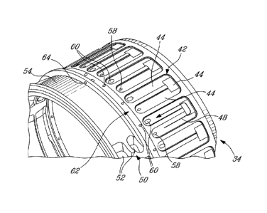
speeds
of gas turbine engine shafts, which must be dissipated. This heat dissipation
is most
often accomplished using fluid cooling, for example oil from the engine's
recirculating
oil system which is sprayed onto the external surfaces of the seal runner
and/or the
carbon ring. However, this spray cooling limits the size envelope and
configuration
possible for shaft seal installations, and further, if inadequately cooling
fluid is
provided or the cooling fluid cannot sufficiently reach/cover the required
surfaces,
sealing performance of such shaft seals can degrade.
[0003] Accordingly, an improved shaft contact seal is sought.
SUMMARY
[0004] In one aspect, there is provided a contact seal assembly for a shaft of
a gas
turbine engine, comprising: one or more carbon ring segments mounted in a
fixed
position within a housing; and an annular seal runner adapted to be connected
to the
shaft of the gas turbine engine and rotatable relative to the carbon ring
segments,
the seal runner being disposed adjacent to and radially inwardly from the
carbon ring
segments and abutting thereagainst during rotation of the seal runner to form
a
contact interface between the seal runner and the carbon ring segments which
forms
- 1 -
CA 02852582 2014-05-23
a substantially fluid tight seal; the seal runner comprising concentric inner
and outer
annular portions which are radially spaced apart to define therebetween at
least one
internal fluid passage, said fluid passage defining a tortuous fluid flow path
through
the fluid passage and being adapted to receiving cooling fluid therein for
cooling the
seal runner from within, and the seal runner having one or more oil scoops
integrally
formed in one of the inner and outer annular portions and disposed in fluid
flow
communication with the internal fluid passage, the oil scoop feeding cooling
oil into
said fluid passage.
[0005] In another aspect, there is provided a gas turbine engine comprising
one or
more compressors, a combustor and one or more turbines, at least one of said
compressors and at least one of said turbines being interconnected by an
engine
shaft rotating about a longitudinal axis thereof, at least one contact shaft
seal being
disposed about the rotating engine shaft to provide a fluid seal therewith,
the contact
shaft seal comprising one or more carbon ring assemblies having carbon ring
segments mounted in a fixed position within a housing and an annular seal
runner
fixed to the engine shaft for rotation within the carbon ring assemblies, the
seal
runner abutting the carbon ring segments during rotation of the seal runner to
form a
contact interface therebetween which forms a substantially fluid tight shaft
seal, the
seal runner having concentric inner and outer annular portions which are
radially
spaced apart to define therebetween at least one internal fluid passage
enclosed
within the seal runner, the fluid passage defining a tortuous fluid flow path
through
the fluid passage and receiving cooling fluid therein for cooling the seal
runner from
within, the seal runner having one or more oil scoops integrally formed in one
of the
inner and outer annular portions and disposed in fluid flow communication with
the
internal fluid passage to feed cooling oil into said fluid passage.
[0006] In a further aspect, there is provided a method of cooling an annular
seal
runner of a shaft seal assembly having carbon ring segments abutting the seal
runner during relative rotation therebetween to form a contact interface
between an
outer runner surface of the seal runner and an inner surface of the carbon
ring
segments to form a fluid seal around the shaft, the method comprising:
providing the
seal runner with an internal fluid passage disposed radially between inner and
outer
annular portions of the seal runner; using an oil scoop integrally formed in
the seal
runner to feed cooling oil into the internal fluid passage within the seal
runner; and
internally cooling at least a radially outer portion of the seal runner having
the outer
- 2 -
CA 02852582 2014-05-23
=
runner surface thereon by circulating the cooling oil through the internal
fluid
passage of the seal runner to cool the seal runner from within, including
rotating the
seal runner to collect the cooling oil using the oil scoop and force the flow
of the
cooling oil through the internal fluid passage.
[0007] Further details of these and other aspects of the present invention
will be
apparent from the detailed description and figures included below.
BRIEF DESCRIPTION OF THE DRAWINGS
[0008] Reference is now made to the accompanying figures depicting aspects of
the present invention, in which:
[0009] Fig. 1 is schematic cross-section of a gas turbine engine;
[0010] Fig. 2 is a partial cross-sectional view of a contact seal assembly in
accordance with the present disclosure for sealing a rotating engine shaft of
the gas
turbine engine of Fig. 1, the contact seal assembly including a carbon ring
assembly
and an associated seal runner;
[0011] Fig. 3 is a perspective view of the seal runner of the contact seal
assembly
of Fig. 2;
[0012] Fig. 4 is a partial cross-sectional perspective view of the seal runner
of Fig.
3, taken through a fluid inlet;
[0013] Fig. 5 is a partial cross-sectional perspective view of the seal runner
of Fig.
4, shown with an outer annular portion thereof removed to depict only an inner
annular portion thereof;
[0014] Fig. 6 is a partial perspective view of the inner annular portion of
the seal
runner of Fig. 5;
[0015] Fig. 7 is a partial cross-sectional view of the seal runner of Fig. 4;
[0016] Fig. 8 is a partial cross-sectional view of the seal runner, taken
through a
fluid exit from the internal seal runner fluid passage; and
[0017] Fig. 9 is a partial cross-sectional view of the seal runner, taken
through both
the fluid inlet and a fluid exit.
- 3 -
DETAILED DESCRIPTION
[0018] Fig. 1 illustrates a gas turbine engine 10 of a type preferably
provided for
use in subsonic flight, generally comprising in serial flow communication a
fan 12
through which ambient air is propelled, a multistage compressor 14 for
pressurizing
the air, a combustor 16 in which the compressed air is mixed with fuel and
ignited for
generating an annular stream of hot combustion gases, and a turbine section 18
for
extracting energy from the combustion gases.
[0019] In the depicted embodiment, the turbine section 18 comprises a low
pressure turbine 17 and a high pressure turbine 19. The engine 10 also
preferably
includes at least two rotating main engine shafts, namely a first inner shaft
11
interconnecting the fan 12 with the low pressure turbine 17, and a second
outer shaft
13 interconnecting the compressor 14 with the high pressure turbine 19. The
inner
and outer main engine shafts 11 and 13 are concentric and rotate about the
centerline axis 15 which is preferably collinear with their longitudinal axes.
[0020] The main engine shafts 11, 13 are supported at a plurality of points by
bearings, and extend through several engine cavities. As such, a number of
shaft
seals are provided to ensure sealing about the shafts at several points along
their
length to prevent unwanted fluid leaking from one engine compartment or
cavity. For
example, compressed air in the main engine gas path must be kept separate from
the secondary cooling air or bearing lubrication oil in bearing cavities and
cooling
cavities adjacent to the main engine gas path.
[0021] Referring now to Figs. 2, at least one of the shaft seals used to seal
the
rotating shaft 11 and/or 13 in the engine 10 is a contact seal 20, as will now
be
described in further detail. The contact seal 20 includes generally a number
of
rotationally stationary carbon ring segments 22 which together form at least
one
circumferentially interrupted annular carbon ring assembly and a rotating seal
runner
30 connected to one of the rotating engine shafts of the gas turbine engine 10
(such
as the shaft 13 for example) and rotatable relative to the carbon ring 22. The
carbon
ring segments 22 are arcuate carbon segments circumferentially arranged within
the
seal housing 24, the housing 24 being in turn fastened in fixed position to a
supporting engine support and/or casing segment. Further, as seen in Fig. 2,
the
carbon ring segments 22 may include a pair of axially spaced segmented annular
carbon rings assemblies.
- 4 -
Date Recue/Date Received 2021-09-10
CA 02852582 2014-05-23
[0022] Referring still to Fig. 2, the annular seal runner 30 is located
adjacent to and
radially inwardly from the carbon ring segments 22 to thereby create a
rotating
contact interface between the carbon ring segments 22 and the rotating seal
runner
30, to form a substantially fluid tight seal therebetween when the engine
shaft 13
rotates during operation of the engine 10. More particularly, a radially outer
surface
32 of the seal runner 30 contacts the radially inner surfaces 23 of the carbon
ring
segments 22. As will be seen, the seal runner 30 is internally cooled, in that
the
radially outer contact surface 32 of the seal runner does not require external
spray
cooling but rather is cooled from within by circulating the cooling fluid
(such as, but
not necessarily, oil) internally within the fluid passage 40 formed within the
seal
runner 30. The cooling oil is distributed to the seal runner via one or more
oil
nozzles 21 which feed the cooling oil radially inwardly onto the
circumferentially
extending open topped channel 54 disposed at a forward end 27 of the seal
runner
30.
[0023] As seen in Figs. 3-5, the seal runner 30 comprises first and second
annular
portions 34 and 36 which are concentric with one another, at least partially
axially
overlapping, and radially spaced apart wherein the second annular portion 36
is
radially outwardly disposed from the inner first annular portion 34 such as to
define
an annular fluid passage 40 therebetween, as will be described further below.
[0024] The seal runner 30 may be either formed in a number of different
manners,
and may comprise one, two or more separate components which together form the
present seal runner 30. For example, in one embodiment the seal runner 30 may
be
formed using a three-dimensional printing production technique, whereby the
seal
runner 30 is integrally formed of a single piece (i.e. is monolithic). In
another
possible embodiment of the present disclosure, the seal runner 30 is composed
of
two or more portions, which are separately formed and engaged or otherwise
assembled together to form the finished seal runner 30. In this embodiment,
for
example, the first and second annular portions 34 and 36 are separately formed
and
mated together with the outer, second annular portion 36 radially outwardly
spaced
from the inner, first annular portion 34. The outer, or second, annular
portion 36 in
this case forms an outer runner sleeve which fits over the smaller diameter
inner, or
first, annular portion 34. The radially inner first annular portion 34 and the
radially
outer second annular portion 36 are, in this embodiment, separately formed and
engaged together in radial superposition to form the seal runner 30, making it
a two-
- 5 -
CA 02852582 2014-05-23
part seal runner. More than two components may also be used to form the inner
and
outer annular portions 34, 36, thereby making it a multi-part seal runner.
While the
outer runner sleeve 36 may be engaged to the inner annular portion 34 by a
number
of suitable means, in at least one embodiment the two components of the seal
runner 30 are welded together, for example at two axial weld points 39 (see
Figs. 4
and 7). These welds 39 may be annular, or at least extend partially about the
circumference of the joints between the inner and outer portions 34, 36 of the
seal
runner and disposed at the forward and rearward ends of the outer sleeve
portion
36. Although welds may be used to engage the components of the seal runner 30
together, other suitable engagements means may also be used, such as for
example
only, brazing, bonding, adhering, fastening, etc.
[0025] As noted above, at least one fluid passage 40 is radially defined
between
the first and second annular portions 34, 36, into which cooling oil is fed to
cool the
seal runner 30 in general, and the hot radially outer second annular portion
34
having the outer contact surface 32 thereon in particular. Accordingly, the
fluid
passage 40 is internally formed within the seal runner 30 such that the seal
runner
30 is cooled from within. Cooling oil within the fluid passage 40 will be
forced radially
outward by centrifugal force, thereby ensuring that the cooling oil is
maintained in
contact with the inner surface of the hot outer sleeve portion 36, which
defines the
contact surface on the opposed radially outer surface for rubbing against the
carbon
ring segments 22. Thus, the underside of the runner surface is cooled
internally, by
absorbing the heat therefrom using the circulating oil flow. Further, the
centrifugal
force of the shaft rotating will also generate pumping of the cooling oil,
using the
integrated oil scoops 50 as will be described below.
[0026] As best seen in Figs. 5-6, the internal fluid passage 40 within the
seal
runner 30 is formed by at least one radially-open channel 42 defined in one or
both
of the first and second annular portions 34, 36, such as in the radially inner
first
annular portion 34 for example. As such, when the two annular portions 34 and
36
of the seal runner 30 are concentrically aligned and mated together, the
radially
inwardly facing surface of the outer second annular portion 36 encloses the
open-
toped channel 42 to form the enclosed fluid passage 40. The channel 42, and
consequently the enclosed internal fluid passage 40, is composed of a
plurality of
serially interconnected passage segments 44 which intersect each other to
define a
tortuous fluid flow path through the fluid passage. In one particular
embodiment the
- 6 -
CA 02852582 2014-05-23
segments 44 of the channel 42 define a substantially serpentine shape, however
other configurations and shapes of the channel(s) 42 may also be provided. In
all
cases, the tortuous path formed by the channel or channels 42 causes the
cooling oil
that is circulated through the fluid passage 40 formed by the channel 42 to
more
effectively cool the seal runner 30.
[0027] As seen in Figs. 3 and 6, the seal runner 30 also includes at least one
integrated oil scoop 50 that is integrally formed in the radially inner first
annular
portion 34 of the seal runner 30, forward of the seal runner surface 32 of the
second
annular sleeve portion 36. In the depicted embodiment, the seal runner 30 in
fact
includes three oil scoops 50 which are substantially equally circumferentially
spaced
apart about the inner annular portion 34 of the seal runner 30. Each of the
oil
scoops 50 are disposed in fluid flow communication with the internal fluid
passage 40
within the seal runner 30, and more particularly the oil scoops 50 collect and
feed the
cooling oil into the fluid passage 40 such as to internally cool the seal
runner during
operation of the engine.
[0028] As seen in Figs. 3 and 6, each of the oil scoops 50 may include a pair
of
openings 52 which extend radially inwardly through the first annular portion
34 of the
seal runner 30 in a direction of rotation of the seal runner. The openings 52
of each
of the oil scoops 50 are disposed at an angle such that rotation of the seal
runner 30
causes oil within the radially open topped annular scoop channel 54 in the
upstream
end of the first portion 34 of the seal runner 30 to be scooped up and forced
radially
inwardly through the openings 52 of the oil scoops 50.
[0029] As best seen in Figs. 4-6, cooling oil that is collected by the oil
scoops 50
and forced inwardly through the scoop openings 52 is directed into an annular
distribution channel 56, which is formed in the radially inner surface of the
first
portion 34 of the seal runner 30 and is radially inwardly open. The oil or
other
cooling fluid used will therefore collect in this annular distribution channel
56 during
operation of the engine, as a result of the centripetal forces acting on the
fluid. A
plurality of angled entry holes 58 extend radially outwardly from the inner
distribution
channel 56, and permit fluid flow from the annular distribution channel 56
into the
tortuously shaped internal fluid passage 40, formed between the first and
second
portions 34, 36 of the seal runner 30 as described above.
- 7 -
CA 02852582 2014-05-23
[0030] Referring briefly to Fig. 9, the entry holes 58 may, in one possible
embodiment, permit greater fluid flow therethrough than do the exit holes 64.
This
may be accomplished, for example, by forming the entry holes 58 having greater
diameters than the diameters of the exit holes 64. Alternately or in addition,
there
may be substantially more entry holes 58 provided than exit holes 64. The
fluid flow
rate through the seal runner 30 is therefore able to be controlled as desired,
by
selecting the number, configuration and geometry of the entry and exit holes
or
openings. In one particular embodiment, more than 6 times the number of entry
holes than exit holes are provided, and the diameter of the inlet holes is
greater than
that of the exit holes, for example each of the exit holes is less than % the
diameter
of each of the inlet holes.
[0031] As can be seen in Figs. 7-9, while the internal fluid passage 40 of the
seal
runner 30 may have a tortuous flow path as shown in Figs. 7-8, the fluid
passage 40
is axially elongated and extends axially between the inner and outer portions
34, 36
of the seal runner 30 along at least a major portion of the axially
overlapping length
between the inner and outer portions 34 and 36. The entire fluid passage 40 is
accordingly annular in shape, extending circumferentially about the seal
runner 30
between the inner and outer portions 34 and 36 thereof. When seen in cross-
section
as shown in Figs. 9-11, the fluid passage 40 may axially extend in a direction
that is
substantially parallel to, and concentric with, an axis of rotation 15 of the
engine shaft
13 and thus the axis of rotation of the annular seal runner 30 that is fixed
to the
shaft.
[0032] Once the cooling fluid (ex: oil, or otherwise) enters the internal
fluid passage
of the seal runner 30 via the entry holes 58 as described above, the cooling
fluid
then flows through the tortuous flow path 48 as shown in Fig. 8, i.e. through
the
serially connected serpentine channel segments 44 which make up the channel
42.
This flow of cooling fluid through the internal fluid passage 40 according
acts to cool
the seal runner 30 from the inside, thereby cooling the hotter outer portion
36 of the
rotating seal runner 30 having the radially outer surface 32 thereon which
defines the
rubbing contact interface with the carbon ring segments 22 of the contact seal
assembly 20. This internal cooling of the seal runner 30 may therefore avoid
the
need for external spray cooling, thereby simplifying the cooling oil nozzle
placement
and enabling a more compact contact seal assembly 20.
- 8 -
[0033] As seen in Figs. 6 and 8, once the cooling fluid has circulated through
the
internal fluid passage 40 along the tortuous flow path 48 therewithin, the
fluid exits
the fluid passage 40 via exit passages 60 which communicate with an radially
outwardly opening channel 62 formed in the outer surface of the first annular
portion
34 of the seal runner 30. Cooling fluid within this annular channel 62 is then
able to
circumferentially circulate between the inner and outer portions 34, 36 of the
seal
runner 30 thereby providing further cooling prior to being ejected out from
between
the two portions 34, 36 of the seal runner 30, and back into the open channel
62 for
subsequent recirculation, via outlet holes 64 (see Figs. 6 and 9).
[0034] The contact seal assembly as described herein is believed to provide an
improved shaft seal adapted for use in a gas turbine engine, however the
present
contact seal may also be used for other shaft sealing applications. For
example only,
high speed pumps and compressors used in high speed, high temperature and/or
severe service conditions represent other applications in which the present
rotating
shaft seal may prove viable. The present contact seal and seal runner may be
particularly useful in applications when space is limited and/or enables the
seal
runner to be cooled even when there is no access to the underside of the seal
runner
directly. Thus, cooling fluid nozzles and related configurations may be able
to be
simplified, thereby potentially saving space, weight and/or cost.
[0035] When used in a gas turbine engine 10 such as that depicted in Fig. 1,
the
present contact seal assembly 20 may be disposed about any rotating shaft or
other
element thereof, such as for example about at least one of the main engine
shafts 11
and 13. Alternately, the contact seal assembly 20 may be employed to seal
another
rotating shaft in the gas turbine engine 10 or in another turbomachine, pump,
compressor, turbocharger or the like. The seal runner 30 of the present
contact seal
assembly 20 preferably integrally formed therewith. The seal runner 30 may be
mounted to the shaft using any suitable means, such as by using a threaded
stack
nut 29 which fastens the seal runner in place about the shaft 13, as shown in
Fig. 2.
Regardless, the seal runner 30 is rotationally fixed in place to the shaft 13,
such that
it rotates within the carbon ring segments 22 and remains in contact therewith
when
the shaft 13 rotates. Thus, the contact seal assembly 20 provides a fluid seal
about
the rotating shaft.
[0036] The above description is meant to be exemplary only, and one skilled in
the
art will recognize that changes may be made to the embodiments described
without
- 9 -
Date Recue/Date Received 2022-01-20
CA 02852582 2014-05-23
department from the scope of the invention disclosed. Still other
modifications which
fall within the scope of the present invention will be apparent to those
skilled in the
art, in light of a review of this disclosure, and such modifications are
intended to fall
within the appended claims.
- 10-