Note: Descriptions are shown in the official language in which they were submitted.
CA 02852596 2015-07-03
- 1 -
AROMATIC MISTING SYSTEM AND METHOD
FOR USE WITH A BATHTUB
TECHNICAL FIELD
This specification relates to an aromatic misting system for use with a
bathtub.
BACKGROUND ART
It is known that some aroma have substantial physiological effects on
people. For example, some aroma having a lemon scent has a stimulant effect or
act as
cures for drowsiness because they excite people mentally and they activate the
circulatory
system. Also, aroma diffused by lavender have effects of relieving stress,
anxiety or the
like and further have anti-depressive effects because they relax tension.
Aroma diffused
with rosemary and the like plants have orexigenic and relaxative effects.
Other
compounds are also known that when admixed with water and diffused in a mix
have
effects of sterilization against harmful bacteria or virus and therefore have
effects of
restoration of good health to people.
Nebulizers or diffusers are usually utilized to dispense aromas and essential
oils in a mist in an environment. These scented mists are in contact with the
wall of the
diffuser chamber which tends to be contaminated with aromatic fluid stains or
essential oil
stains. This requires periodic cleaning of the device and the dismantling of
those parts in
contact with the scented oil mist and this is often problematic and time-
consuming.
In these atomizing devices, the mist is usually released in the environment
by a fan associated with the device. These fans generate noise and interfere
with the
relaxing effects of the aromatic mist and the environment in which a person is
disposed for
relaxation. These devices also consist of many parts and are therefore costly
and prone to
malfunction.
SUMMARY OF INVENTION
In accordance with one aspect, there is provided an aromatic misting
system for use with a bathtub having a top opening, said misting system
comprising a
reservoir having an open top end, a removable cover structure disposed in said
open top
end, directional orifice means in said cover structure, liquid atomizing means
sealingly
secured at a bottom end of said reservoir for producing a mist from an
aromatic liquid
disposed in said reservoir, said cover structure having switch actuation means
for
CA 02852596 2015-07-03
- 2 -
actuating a switch to enable said liquid atomizing means when said cover
structure is
positioned into said open top end, level sensing means to sense the level of
said liquid in
said reservoir, and air stream convection means to draw said mist from said
directional
orifice of said reservoir and into the top opening of said bathtub where a
user person
positions itself.
According to another broad aspect, the present invention provides a method
of providing an aromatic mist in a bathtub comprising the steps of:
i) securing a reservoir as claimed in claim 1 on a ledge of said bathtub
and adjacent said top opening thereof;
ii) filling said reservoir with water in admixture with an aromatic substance
and/or essential oils;
iii) fitting said cover structure in said open top end of said reservoir and
at a
predetermined position on said ledge of said bathtub; and
iv) actuating said liquid atomizing means to produce said mist, and wherein
said mist containing an aromatic scent and/or essential oils will flow out of
said reservoir
and into said top opening to form a cloudy mist.
BRIEF DESCRIPTION OF DRAWINGS
A preferred embodiment of the present invention will now be described with
reference to the accompanying drawings in which:
FIG. 1 is a top perspective view of the bathtub on the ledge of
which is
incorporated the aromatic misting system of the present invention;
FIG. 2 is a perspective view illustrating the construction of the
cover
showing the cover being removed from the reservoir;
FIG. 3 is a perspective view showing the cover disposed in a first
position wherein the directional orifice is open;
FIG. 4 is a perspective view, similar to Figure 3, showing the
cover in a
closed position;
CA 02852596 2014-05-26
- 3 -
FIG. 5 is a top
view illustrating the inner construction of the reservoir
showing the position of the piezoelectric transducer, level sensor and cover
support as
well as the reed switch position;
FIG. 6 is a top
view of the cover showing the lower ledge construction
thereof and the location of the magnetic element;
FIG. 7 is a bottom
view of the reservoir showing the position of the
reed switch and the piezoelectric transducer;
FIG. 8 is a perspective view of a reed switch;
FIG. 9 is a
perspective view showing the construction of the reservoir;
FIG. 10 is a top view of the reservoir with the cover removed;
FIGs. 11A and 11B are sectional side views of the reservoir;
FIG. 12 is a sectional front view of the reservoir; and
FIG. 13 is a top view of Figure 9.
DESCRIPTION OF PREFERRED EMBODIMENTS
Referring now to the drawings and more particularly to Figure 1, there is
shown generally at 10 a bathing tub having a contour ledge 11 in which is
secured the
aromatic mist producing device 12 of the present invention in combination with
a
bathtub. The bathtub may also be a hydro massage tub, etc... The mist
producing
device 12 is located adjacent an end 13 of the bathtub where a user person is
usually
sitting to receive a relaxing treatment by the mist. The mist producing device
is
disposed at any location on the ledge portion of the bathtub whereby the user
person
will benefit from the essential oils and aromas present in a mist produced in
the device
12. It is preferred that the bathtub be filled with hot water to enhance the
relaxing
benefit, but the mist producing device operates without hot air present at its
outlet.
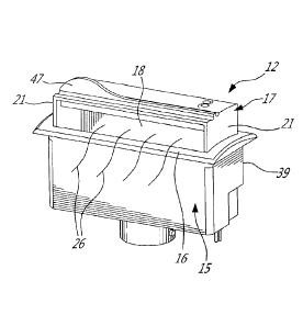
Figures 9 to 13 show the construction of the mist producing device 12.
As hereinshown, the device comprises a reservoir 15 which has an open top end
16. A
removable cover structure 17 is removably disposed in the open top end 16. The
cover
has a directional orifice 18 formed in a side wall 19 thereof. The cover has a
closed
rear wall 20 and opposed side walls 21 and a top wall 22. The construction of
the
removable cover 17 is also well illustrated in Figure 2. The reservoir 15 has
a bottom
wall 23 in which is secured a piezoelectric diffusing element 24 which
vibrates at high
frequency whereby to atomize the liquid 25 (see Figure 12) placed in the
reservoir to
produce a mist. The liquid 25 is admixed with essential oils or aromatic
substances or a
CA 02852596 2015-07-03
- 4 -
combination whereby an aromatic mist, as illustrated by flow lines 26 in
Figure 9, is caused
to exit the directional orifice 18 in a manner as will be described later. As
shown in Figure
7, the bottom wall 23 is also provided with a switch, herein a reed switch 30,
secured
thereto at a predetermined location. The reed switch 30 is better illustrated
in Figure 8 and
is of a conventional design. The basic reed switch consists of two
ferromagnetic nickel-
iron wires 31 located in a glass capsule 32. The two wires 31 and 31' have a
flat free end
inside the glass capsule 32 which are spaced-apart to form a gap. These two
reeds act as
magnetic flux conductors and when exposed to an external magnetic field from a
permanent magnet the contacts will close. Accordingly, the reed switch is a
normally open
contact switch (biased to the open condition by default).
As shown in Figure 6, the rear wall 20 of the removable cover 17 is
provided with a permanent magnet 33 embedded or otherwise secured adjacent a
lower
edge 34 of the rear wall 20 and disposed at a location such that when the
cover is in a first
operative position, as shown in Figure 9, the permanent magnet 33 is disposed
close to
the reed switch causing the switch to close and operate the piezoelectric
transducer if
there is liquid in the reservoir. Accordingly, the cover acts as a switch
actuator.
As also shown in Figure 6, the cover end walls 21 also have an undercut
portion 36 thus defining a seating formation 37 for seating engagement on
support
formations 38 (see Figures 10, 11A and 11B) formed in the reservoir for
supporting the
cover structure at a first open operative position as shown in Figure 9. When
the cover is
disposed in a closed position, as shown in Figure 4, by rotating the cover
with the orifice
18 facing the rear wall 39 of the housing, the seating formation 37 or ledge
no longer rests
on the support formations 38 and accordingly, the lower edge 39 of the rear
wall 20 of the
cover will sit on the bottom wall 23 of the reservoir. Further, the permanent
magnet 33 is
now located away from the reed switch in an opposed corner 40 (see Figure 5)
of the
reservoir and the switch will not close. In Figure 5, the reed switch is shown
located in a
depression formed in the wall of the reservoir, namely in the protrusion 41,
as seen from
inside the reservoir. The piezoelectric transducer assembly is also provided
with a level
sensor 42 at a proper location therein, which projects into the housing to
sense the level of
liquid in the reservoir. The sensor cuts out the piezoelectric element when
the water level
is too low to produce a mist from the remaining liquid in the reservoir.
CA 02852596 2014-05-26
- 5 -
Referring to Figures 6 and 7, it can be seen that in order to mount the
misting system or device 12, a cavity 45 is formed in the ledge 11 of the
bathtub. The
reservoir 15 is also provided with a top contour flange 46 and a double-sided
adhesive
tape is disposed behind and about the flange to attach the reservoir in a seal-
type
.. manner around the cavity to prevent the infiltration of water. As shown in
Figure 6, the
cover is also provided with a gripping top flange 47 to facilitate the removal
and
insertion of the removable cover 17 into the top open end of the reservoir, as
is
illustrated in Figure 2.
In operation, the reservoir is filled with water and essential oils and/or
.. other aromatic liquid substances. The bathtub is also filled with warm
water to a
predetermined level or the bathtub may remain empty to act as an open
enclosure.
The cover of the reservoir is pushed into the reservoir whereby to actuate the
reed
switch which enables the piezoelectric transducer module. The cover is
disposed such
that the directional orifice 18 faces inwardly of the bathtub. A hot air mist
is produced in
.. the reservoir above the water level by the hot water in the bathtub and is
present at the
directional orifice 18. The hot air above the water level of the bathtub
creates a hot
environment adjacent the directional orifice 18 wherein the cool mist
generated by the
piezoelectric transducer creates a temperature differential at the orifice 18
between the
hot air of the bathtub and the cold air of the mist, drawing the mist out of
the reservoir
through this directional orifice to mix with hot vapors present on the surface
of the
bathtub. This also creates a misty cloud over the bathtub in the presence of
the user
person and close to the face of the user person where aromatic vapors are
deposited
on the exposed body portions of the user wherein essential oil droplets will
deposit and
provide a smoothness to the skin and a soothing treatment and facial treatment
depending on the essential oils admixed with the water in the reservoir. The
reservoir
can be positioned at any location along the contour ledge of the bathtub.
Also, as
mentioned above, the bathtub may not have water therein and only acts as an
open
enclosure to support a user person. The mist created by the piezoelectric
transducer
would simply be forced out of the housing by the volume produced in the
enclosure and
.. propagate in the area of the bathtub and slowly descend in the bathtub.
The cleaning of the misting system is simplified in that the cover is
removable and can be cleaned separately from the reservoir. Because the
reservoir is
completely open, it facilitates the insertion of a sponge pad or cloth as well
as cleaning
liquids or sprays inside the reservoir for cleaning. The reservoir is
hereinshown
CA 02852596 2014-05-26
- 6 -
constructed of ABS plastics and the piezoelectric transducer is tightly
secured to the
bottom wall on a gasket 50, as shown in Figure 7. As also shown in that
Figure, the
piezoelectric transducer 24 is not exposed to the water within the reservoir.
The
piezoelectric transducer has a dome-shaped sealed casing through which high
frequencies are generated into the liquid. Accordingly, the inner surface of
the
reservoir is a sealed surface.
It is within the ambit of the present invention to cover any obvious
modifications of the preferred embodiment described herein, provided such
modifications fall within the scope of the appended claims.