Note: Descriptions are shown in the official language in which they were submitted.
CA 02852677 2014-04-16
WO 2013/059223
PCT/1JS2012/060480
High Speed Autofocus System
Technical Field
This invention generally relates to the optical inspection of electronic parts
and
more specifically to an autofocus system for use in such optical inspection.
Background Art
Optical inspection of electronic parts such as such as wafers, circuit boards,
flat
panel displays, multi chip modules, and high-density electronic packages
requires the
use of high resolution optics to detect small defects in the part. In addition
the high
resolution optics part must be kept in focus during the entire inspection to
see the
1 0 defects. FIG. 1 is the example of a part 1-1 with variations in surface
height Z in both
the scanning direction 1-2 and in an orthogonal direction relative to the
scanning
direction. Newly introduced circuit boards with embedded dies are examples of
such
parts and are recognized as being difficult to image because the surfaces
being imaged
are subject to height variations caused by the embedded die or circuits placed
on and
between the substrate layers and the recognized characteristics that the
substrate itself
will warp.
FIG. 1 is helpful in understanding problems that exist when prior art
apparatus
is required to image defects in various parts. In the prior art, a camera, not
shown,
scans over the surface of a part in a scanning direction 1-2. As the scan
images an area
such as shown in FIG. 1 which is transverse to the scanning direction 1-2, the
image
taken by the camera must be in focus. The part shown in FIG. 1 has a range of
height
variations, shown by arrows 1-3 that must be within the depth of field of the
camera
optics. With prior art imaging apparatus, a particular focus point selected
for the
camera could arbitrarily be at the top 1-5 of or the bottom 1-6 of the part or
at any
intermediate position. Given this, optics design of the imaging optics sets
the required
depth of field, preferably twice the distance between the top 1-5 and bottom 1-
6 of the
part as shown by arrows 1-7 and 1-8 that depict a depth that will cover the
range of
height variations. However, as known and described in greater detail later,
the depth
of field for an optics system also determines the resolution of the image.
Such
resolutions often limit image quality that will prevent the detection of small
defects in
the part.
To inspect the part for defects a camera is frequently used to scan the part
in a
serpentine pattern as illustrated by the contiguous strips A through E in FIG.
2. The
width of the camera's field of view is represented by rectangle 2-1. Various
CA 02852677 2014-04-16
WO 2013/059223
PCT/US2012/060480
2
techniques have been described in the art to maintain focus during such
inspections.
U.S. Patent No. 7,015,445 to Bishop for "Method for Optimizing Inspection
Speed in
Low, and Fluorescent Light Applications without Sacrificing Signal to Noise
Ratio,
Resolution, or Focus Quality" describes the use of a triangulation sensor to
maintain a
constant distance between the imaging optics and part as the part is scanned.
FIG. 3
shows a wavy part 3-1 at an incline 0, imaging optics 3-2 and an imaging
camera 3-3.
As the part is scanned the imaging optics 3-2 and imaging camera 3-3 are
raised and
lowered as a unit to keep the surface of the part within the optical depth of
field 3-4 of
the imaging optics. Conceptually the part, the optics, or the combination of
the optics
and camera can be moved to maintain focus.
FIG. 4 shows the use of a triangulation sensor with an optical source 4-1,
illumination beam 4-2 and position sensor 4-3. The triangulation sensor scans
ahead
of the camera as indicated by arrow 4-4. The position at which optical beam 4-
5 hits
the position sensor indicates the distance to the part 4-6. In this FIG. 4,
the imaging
camera optics has a depth of field (DOF) 4-7. This distance measurement is
used in a
feedback loop to mechanically move either the imaging optics or the part
relative to
each other to maintain focus. FIG. 5 shows how the position of the beam onto
position
sensor 5-1 moves as a function of the distance to the part. Three surfaces at
different
distances represented by surfaces 5- 3, 5-4, and 5-5, are projected onto
sensor 5-1 at
positions 5-3', 5-4', and 5-5' respectively. These distance measurements arc
used in a
feedback loop mechanically to move either the optical head or the part as a
function of
the measured height to maintain focus.
There are two limitations to these focusing methods. First, if an illumination
beam 4-2 in FIG. 4 hits the part at a material boundary the distance
measurement may
be incorrect. Referring to FIG. 6 and specifically to FIG. 6A, when optical
beam 6-1
from the triangulation sensor hits highly reflective material 6-2, the entire
illumination
spot 6-3 sits on material 6-2. The image of this spot creates a symmetrical
shaped
beam 6-4 on sensor 6-5. If the material beneath the sensor now changes, as the
part is
scanned to one with a lower reflectivity, represented by 6-6 in FIG. 6B, a
lower
intensity spatially symmetrical spot represented by 6-7 is projected onto
sensor 6-5.
So long as projected spots 6-7 and 6-4 are spatially symmetrical, the center
of mass of
the spots, which represents the distance to the part, will be the same and the
correct
focus distance will be calculated. If, however, the illumination spot 6-3
falls on a
material boundary as in FIG. 6C, it is spread between highly reflective
material 6-2
PCT/US12/60480 17-05-2013 PCT/US2012/060480 18.03.2014
.
CA 02852677 2014-04-16
REPLACEMENT PAGE
= 3
and lower reflective material 6.3. In this event, the spot projected onto the
sensor will
not be symmetrical and the distance to the part will be incorrectly calculated
to be at
position 6- 8 when the correct distance should be at position 6-7 because the
center of
mass of the spot no longer represents the correct distance to the part
5 Second, in FIG. 7 an imaging camera 7-1 with imaging optics 7-2 moves in
the
focus direction along a Z axis 7-3 to maintain constant distance to the
surface apart
7-4 while focus distance is adjusted dynamically as the part is scanned in the
Y
direction. Focus distance for the entire imaging camera is based on a series
of single
= point measurements along a narrow line in the direction of scan. No
measurements are
10 taken perpendicular to
the direction Of scan. This implies that across the width of the
camera, or width of each scaimed.strip A ¨E shown in FIG. 2 all features on
the
surface must lie within the optical depth of field of the imaging optics
indicated by
arrow 3-4 in FIG, 3. As will be apparent any feature not within the depth of
field will
be out of focus.
15 = As the part is scanned,
the focus measurement unit may pass over high or low
features in the part. Some focus distances may be calculated based on the
distance to a
high feature while other focus distances may be calculated based on the
distance to a
low feature. This implies that the optical depth of field of the imaging
optics must be
= sufficiently large to insure proper focus regardless of whether a high or
low feature
20 was beneath the focus
measurement unit at the time when the focus measurement was
calculated. Calculating focus based only on measurement values along a line in
the
direction of scan will have this limitation, regardless of, how many
measurements are
acquired, how fast the calculations are computed, the specific method of
measurement
or type of measurement device.. A preferred device is a single point
triangulation
25 sensor; single-point
confocal sensors, single point capacitive sensors and others may
. be substituted depending upon the performance criteria to be provided by the
inspection apparatus.
For current focus tracking technology to properly function the depth of focus
of
the imaging optics, indicated as arrow 8-1 in FIG, 8, must be sufficiently
large to
30 guarantee focus for all
the possible features heights that may be used to calculate the
focus distance. It is important to note that FIG. 8 represents the surface of
the part in
the X axis which is perpendicular to the direction of mechanical scan. FIG. 8
also
represents the image projected onto the long axis of a linear CCD scan camera
as
=
represented by block 2-1 in FIG. 2. Unfortunately requiring this large depth
of field =
=
AMENDED SHEET - IPEA/US
CA 02852677 2014-04-16
WO 2013/059223
PCT/US2012/060480
4
seriously limits the spatial resolution and defect detection capabilities of
the inspection
system. More specifically, the optical depth of focus (DOF) is given by the
equation:
A
DOF = ________________________________
2NA2
and Resolution is given by the equation:
Resolution = ¨2NA
where:
A, = Wavelength of light imaged onto the camera, and
NA = numerical aperture of the imaging optics
As known and demonstrated by the foregoing relationships, large depth of
focus (DOE) requires a small numerical aperture (NA) while high resolution
requires a
large numerical aperture. As (NA) becomes smaller, the level of light reaching
the
1 0 imaging camera, also decreases and this impacts the contrast in the
final image. These
criteria impose limitations on the inspection of parts that can prevent the
construction
of imaging optics with both a large depth of focus and a high resolution. As
will be
apparent, if the part being inspected must stay in focus, current inspection
systems
sacrifice the resolution of the imaging optics which thereby inherently limits
the ability
1 5 to detect small defects.
Table 1 is a list of commercially available lenses from the Zeiss Corporation.
The table lists the depth of focus, numerical aperture, resolving power, light
collection
coefficient, light collection cone angle, working distance magnification and
part
number for each lens.
81779191
Table 1 Commercially Available Objective Lenses From Zeiss
Magnification/ Zeiss Numerical Light Light
Resolving Depth of Working
pixel size Part Aperture Collection Collection Power for
Focus Distance
(microns) Number Coefficient Cone Angle X=0.55 --
X=0.55 -- (WD)
(degrees) (Microns) (Microns)
(NA) (NA2) 0=2xsinl(NA) X A.
2xNA 2xNA2
1.25x/10.4 442300 0.035 0.0012 4.0 7.8 229 3.9
nun
2.5x/5.2 442310 0.075 0.0056 8.6 3.6 49 9.4 mm
5x/2.6 440320 0.15 0.0225 17 1.8 12.2 13.6
mm
5x/2.6 0.25 0.0625 29 1.1 4.4
10X/1.3 442832 0.25 0.0625 29 1.1 4.4 12.7
mm
10X/1.3 442330 0.30 0.0900 35 0.9 3.1 5.7 mm
20X/0.65 442840 0.40 0.1600 47 0.7 1.7 9.8 mm
10X/1.3 440135 0.50 0.2500 60 0.5 1.1 2.0
min
20X/0.50 442340 0.50 0.2500 60 0.5 1.1 .1.4
mm
Note that the 1.25X lens with an NA of 0.035 has a depth of focus of 229
5 microns whereas the 20X lens with an NA of 0.50 only has a depth of
focus of 1.1
microns. Unfortunately, unless all the features in the field of view of the
inspection
camera vary in height less than 1.1 microns, the 20X 0.5 NA lens cannot be
used to
inspect the part. Therefore many inspection systems are forced to use low NA
optics
to maintain focus and are unable to inspect very small features that require
high
magnification and high resolution.
Disclosure of Invention
Therefore, it is an object of this invention to provide a method and apparatus
for providing high-speed autofocusing that enables features on a part to be
identified
based on their height and focused upon during inspection thereof.
Another object of this invention is to provide high-speed autofocusing that
enables features on a part to be identified based on their height and focused
upon
during inspection thereof with imaging optics that provides sufficiently high
resolution
and depth of field to detect small features and defects on the part.
CA 2852677 2018-07-19
81779191
5a
According to an aspect of the present invention, there is provided a method
for
inspecting a part by taking a plurality of images of different image fields of
the part with an
imaging camera having imaging optics with a fixed resolution and depth of
field wherein the
surface of the part is characterized by height variations within a given image
field and wherein
the imaging optics depth of field has a value such that focusing on any point
in the given
image field does not guarantee that the entire corresponding image will be in
focus, said
method comprising the steps of: A) acquiring image data of height variations
of the part
surface from illumination received at a first frequency for a given image
field using a focus
camera during a scanning operation where the part is being scanned along a
scan axis from a
first position relative to the imaging optics to a second position relative to
the imaging objects
and during operation of the imaging camera responding to illumination at a
second frequency
that is non-interfering with the first frequency, B) sampling the height
variations from the
image data of the part surface at multiple positions for the given image field
wherein the
sampling is performed within a specified region of the given image field
determine a range of
height variations of the surface in the given image field, C) determining a
focus position for
the imaging optics for each image based upon the range of height variations
such that surfaces
within the range of height variations in the given image field will be within
the depth of field
for the imaging optics, and D) moving the imaging optics to the focus position
for the given
image field whereby an image acquired by the imaging camera will be in focus
across the
given image field while the focus camera acquires image data of height
variations of the part
for a subsequent image field during the scanning operation.
According to another aspect of the present invention, there is provided
apparatus for
inspecting a part by taking a plurality of images of different image fields of
the part with an
imaging camera having imaging optics with a fixed resolution and depth of
field wherein the
surface of the part is characterized by height variations within a given image
field and wherein
the image optics depth of field has a value such that focusing on any point in
the given image
field does not guarantee that the entire corresponding image will be in focus,
said apparatus
comprising: A) a focus camera that acquires image data of height variations of
the part surface
from illumination received at a first frequency for a given image field during
a scanning
operation where the part is being scanned along a scan axis from a first
position relative to the
CA 2852677 2018-07-19
81779191
5b
imaging optics to a second position relative to the imaging optics; B) an
imaging camera that
responds to illumination at a second frequency that is non-interfering with
the first frequency
during the scanning operation; C) a sampling processor that samples the height
of the part
surface at multiple positions for the given image field wherein variations
from the image data
samples are selected to determine a range of height variations of the surface
in the given
image field; D) a focus processor that determines a focus position for the
imaging optics for
each image based upon the range of height variations such that surfaces within
the range of
height variations in the given image field will be within the depth of field
for the imaging
optics; and E) an actuator that moves the imaging optics to the focus position
for the given
image field whereby an image acquired by the imaging camera will be in focus
across the
given image field while the focus camera acquires image data of height
variations of the part
for a subsequent image field.
In accordance with some embodiments, a method for inspecting a part takes a
plurality of images of different image fields of the part with an imaging
camera having
imaging optics with a fixed resolution and depth of field. The surface of the
part is
characterized by height variations within a given image field and by the image
CA 2852677 2018-07-19
81779191
6
According to an aspect of the present invention, there is provided a method
for
inspecting a part by taking a plurality of images of different image fields of
the part with an
imaging camera having imaging optics with a fixed resolution and depth of
field wherein the
surface of the part is characterized by height variations within a given image
field and wherein
the imaging optics depth of field has a value such that focusing on any point
in the given
image field does not guarantee that the entire corresponding image will be in
focus, said
method comprising the steps of: A) acquiring image data of height variations
of the part
surface from illumination received at a first frequency for a given image
field using a focus
camera during a scanning operation where the part is being scanned along a
scan axis from a
first position relative to the imaging optics to a second position relative to
the imaging optics
and during operation of the imaging camera responding to illumination at a
second frequency
that is non-interfering with the first frequency, B) sampling the height
variations from the
image data of the part surface at multiple positions for the given image field
wherein the
sampling is performed within a specified region of the given image field
determine a range of
height variations of the surface in the given image field, C) determining a
focus position for
the imaging optics for each image based upon the range of height variations
such that surfaces
within the range of height variations in the given image field will be within
the depth of field
for the imaging optics, and D) moving the imaging optics to the focus position
for the given
image field whereby an image acquired by the imaging camera will be in focus
across the
given image field while the focus camera acquires image data of height
variations of the part
for a subsequent image field during the scanning operation.
According to another aspect of the present invention, there is provided
apparatus for
inspecting a part by taking a plurality of images of different image fields of
the part with an
imaging camera having imaging optics with a fixed resolution and depth of
field wherein the
surface of the part is characterized by height variations within a given image
field and wherein
the image optics depth of field has a value such that focusing on any point in
the given image
field does not guarantee that the entire corresponding image will be in focus,
said apparatus
comprising: A) a focus camera that acquires image data of height variations of
the part surface
from illumination received at a first frequency for a given image field during
a scanning
operation where the part is being scanned along a scan axis from a first
position relative to the
CA 2852677 2018-11-28
81779191
6a
imaging optics to a second position relative to the imaging optics; 13) an
imaging camera that
responds to illumination at a second frequency that is non-interfering with
the first frequency
during the scanning operation; C) a sampling processor that samples the height
of the part
surface at multiple positions for the given image field wherein variations
from the image data
samples are selected to determine a range of height variations of the surface
in the given
image field; D) a focus processor that determines a focus position for the
imaging optics for
each image based upon the range of height variations such that surfaces within
the range of
height variations in the given image field will be within the depth of field
for the imaging
optics; and E) an actuator that moves the imaging optics to the focus position
for the given
image field whereby an image acquired by the imaging camera will be in focus
across the
given image field while the focus camera acquires image data of height
variations of the part
for a subsequent image field.
In accordance with some embodiments, a method for inspecting a part takes a
plurality of images of different image fields of the part with an imaging
camera having
imaging optics with a fixed resolution and depth of field. The surface of the
part is
characterized by height variations within a given image field and by the image
optics depth of
field such that focusing on any point in the given image field does not
guarantee that the entire
corresponding image will be in focus. The height of the part surface is
sampled at multiple
positions in the given image field with a sample spacing that is sufficiently
small to determine
the range of height variations of the surface in the image field. A focus
position for the
imaging optics for each image is determined based upon the sampled heights for
the given
image field such that all surfaces of interest in the image field will be
within the depth of field
for the imaging optics. The imaging optics is moved to the focus position for
the given image
field whereby the image will be in focus across the image field.
Brief Description of the Drawings
The appended claims particularly point out and distinctly claim the subject
matter of
this invention. The various objects, advantages and novel features of some
embodiments of
this invention will be more fully apparent from a reading of the following
detailed description
CA 2852677 2018-11-28
81779191
6b
in conjunction with the accompanying drawings in which like reference numerals
refer to like
parts, and in which:
FIG. 1 depicts a portion of a part for inspection with variations in surface
height;
FIG. 2 depicts a prior art autofocus methodology;
FIG. 3 depicts a part with a wavy portion at an incline;
FIG. 4 depicts a prior art optical inspection system that incorporates
triangulation;
FIG. 5 depicts a schematic diagram showing distance from surfaces positioned
at
different heights with respect to a position sensor.
FIG. 6 includes FIGS. 6A, 6B and 6C. FIG. 6A depicts a graph of intensity
sensed by a
.. sensor on a reflective material on a part. FIG. 68 depicts a graph of
intensity sensed by a
sensor on a lower reflective material on a part. FIG. 6C depicts a graph of
intensity sensed by
a sensor on a material boundary of a part.
FIG. 7 depicts a schematic diagram of a prior art imaging system.
FIG. 8 depicts a schematic diagram of depth of focus for imaging optics.
FIG. 9 depicts a schematic diagram of a focal plane for imaging optics at
different
surface heights of a part.
FIG. 10 depicts a schematic diagram of two lenses with different depths of
field.
FIG. 11 depicts a schematic diagram of a lens positioned at two different
heights with
respect to a top surface of a part.
FIGS. 12A and 12B are block diagrams of two embodiments of this invention;
FIG. 13 depicts a schematic diagram of projection of a line pattern onto a
surface of
varying heights and a corresponding projection onto a camera.
CA 2852677 2018-11-28
81779191
6c
FIG. 14 depicts a schematic diagram of projection of a line pattern onto a
surface of
varying heights and a corresponding projection onto a camera.
FIG. 15 depicts the relationship between a focus line and field of view.
FIG. 16 are photographs of inspected images taken by prior art apparatus and
apparatus of an embodiment of this invention.
CA 2852677 2018-11-28
81779191
7
Description of Illustrative Embodiments
An intelligent autofocus system in accordance with embodiments of this
invention
analyzes the surface heights of the features in a part in real time as the
part is scanned to create an
optimally focused image for inspection of the desired features in the part. It
can be
implemented as a stand-alone unit placed in advance of the inspection camera
or
incorporated into a real time through the lens inspection system.
One feature of this invention is the ability to dynamically compute and
mechanically track the optimal focal plane for a given imaging optics during
inspection of the part. As one example, consider FIG. 9 which shows imaging
optics
with depth of field indicated by arrow 9-1. Using the prior art technology,
the imaging
optics would either be focused on the lower surface 9-2 or upper surface 9-3.
If the
imaging optics were focused on lower surface 9-2, the top surface 9-3 will be
out of
focus. Likewise, if an imaging optics were focused on top surface 9-3, the
lower
surface will be out of focus. As the part is scanned both surfaces may appear
beneath
the prior art focusing system. At some positions the top surface may be in
focus, and
at other positions the lower surface may be in focus, so there is no way of
knowing
which surface will be in focus at any given time as the part is scanned. This
makes
high resolution inspection nearly impossible. One feature of this invention is
to
provide a method of intelligently identifying the heights of both surfaces, to
determine
an optimal focus plane spaced between the two surfaces indicated by position 9-
4 that
will enable both surfaces to remain within the optical depth of field of the
given
objective during the inspection of the part.
In many applications the resolution required for inspection is so high and
depth
of field is so low or the height difference between features is so large such
that is not
possible to keep all surfaces in focus simultaneously as the part is
inspected. This is
illustrated in FIG. 10 which shows a medium resolution lens 10-1 and higher
resolution lens with lower depth of field 10-2. Referring to FIG, 11, if such
a part is to
be inspected with high resolution, low depth of field optics 11-1, it must be
decided
prior to scanning the part whether the specific scan will inspect the lower
surface 11-2
or the upper surface 11-3. In applications such as wafers, high density
interconnect
modules, and printed circuit boards, the part consists of metal conductors
placed onto a
substrate. The metal conductors, which form the top surface, are the primary
features
of interest to be inspected for defects. This invention provides means to
dynamically
CA 2852677 2018-07-19
CA 02852677 2014-04-16
WO 2013/059223
PCT/US2012/060480
8
compute the height of the metal upper surface 11-3 and keep it in focus as the
part is
scanned.
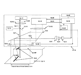
Referring to FIG. 12A, as a part is scanned and inspected in visible light
(350nm to 700nm) as indicated by arrow 12-1, an infrared beam 12-2 (780nm, for
example) passes through the optics and is used to maintain focus. The infrared
beam
from a focus illumination source 12-3 comprising a laser diode, solid state
LED, or any
other light-emitting device is collimated by lens 12-4. The collimated light
passes
through a cylinder lens 12-5 and beam splitter 12-6 to reflect from a dichroic
mirror
12-7 through a lens 12-8 to project a line 12-9 onto the part 12-11. This
focused beam
is positioned off axis to illuminate only half of the optical field. So the
infrared beam
is imaged onto the part at an angle 0, relative to the surface of the part as
illustrated in
FIG. 12A. Due to the surfaces being at different heights in the part, one side
of the
beam projects onto an upper surface 12-10 at a given position in X and the
other side
of the beam projects onto a lower surface 12-11 at a different position in X.
Light rays
from the line image projected onto these surfaces then pass back through lens
12-8,
reflect from dichroic mirror 12-7 and beam splitter 12-6 and then are focused
by a lens
12-12 onto a positioning or height measurement camera 12-13.
In one embodiment the entire focus path operates in the infrared wavelength
(780 nm, as an example) so this focus light does not interfere with the
visible light
inspection path that operates in the range of (350 -700) nm. The visible light
path
consists of an illumination source 12-14 and light from that source 12-14
reflects from
a beam splitter 12-15 to pass through dichroic filter 12-7 which passes the
visible light
and reflects the infrared light. This visible beam then passes through
broadband
imaging lens 12-8, which also passes both visible and near infrared light. The
reflected visible light image then returns through lens 12-8, passes through
dichroic
filter 12-7 and beam splitter 12- 15 to be imaged by lens 12-16 onto
inspection camera
12-17. Other means may be used to produce light 12-14 used by inspection
camera
12-17. For example, some parts to be inspected may have an organic single
layer, an
organic non -tranparant layer, or very opaque organic material, in which only
the top
metal surface needs to be inspected. In such cases there is no interference or
image
artifacts caused from lower layer images, which could confuse the auto focus
apparatus. In such an application an appropriate laser could be substituted
for the
source 12-3 thereby to cause the top surface to fluoresce. Beam splitter 12-15
would
be replaced by a dichroic mirror to reflect the laser and permit fluorescence
returning
PCT/US12/60480 17-05-2013
PCT/US2012/060480 18.03.2014
CA 02852677 2014-04-16
REPLACEMENT PAGE
9
=
from the part to reach inspection camera 12-17. A laser blocking filter 12-26
to allow
only the returning fluorescing rays and also to block any laser illumination
light from
reaching the inspection camera 12-17 is also placed in front of camera 12-17.
This
fluorescing image may produce better contrast of the conductors on the organic
surface. = =
Referring to FIG. 13 and to explain in greater detail how the autofocus
system.
operates, consider a line-shaped beam 13-1, emanating from optical lens 13-2
that
illuminates a part at an angle 0 relative to the surface of the part as shown
in FIG. 13.
The position that the line hits the top surfaces 13-3 and 13-4 will be offset
in the Y
=
= 10 direction from the position that the line hits the
lower surface 13-5 by a distance d such
that:
= d = h tan(0)
where:
h = height difference between the surfaces, and
= angle of the illumination beam relative to a line Perpendicular to the
15 surface.
Lens 13-2 in FIG. 13 corresponds to lens 12-8 in FIGS. 12A and 12B. The
. image of the projected line pattern is projected onto camera
13-6 which corresponds to
the height measurement camera 12-13 in FIGS. I2A and 12B. Lines 13-3, 13-4,
and
13-5 are imaged onto camera 13-6 as lines 13-3', 13-4', and 13-5'
respectively.
=
20 Camera pixels are organized into rows Rand columns C. Arrow 13-7 points
to
the left- most column in the camera 13-6. The row R position of the data on
camera
= 13-6 indicates the height of the different surfaces on the part. By
intelligently
_ analyzing the image, and more specifically the row R
position of the data, one can
determine the location of the top and bottom surfaces and mechanically drive
the
=
=
25 focusing lens, camera and optics to track the desired surface.
As an example, consider a high resolution, high NA optical lens 14-1 in FIG..
14 with corresponding shallow depth of field 14-2. The image of the projected
line
. pattern is imaged onto camera 14-3. The camera field may be divided into
upper -
region 14-4 and lower region 14-5. The row positions R of the information in
upper
30 region 14-4 corresponds to the height of the upper surfaces on the part.
The row
positions R of the information in lower region 14-5 correspond to the heights
of the
lower surfaces on the part.
=
=
AMENDED SHEET -1PEA/US =
=
CA 02852677 2014-04-16
WO 2013/059223
PCT/US2012/060480
If the goal is to keep the top surface in focus, then only data in upper
region
14-4 is analyzed to determine the highest and lowest row position of the data
in region
14-4. This corresponds to the height variation of the top surface of the part
perpendicular to the direction of mechanical scan across the width of the
camera 14-3.
5 The midpoint of this height variation is calculated and corresponds to
height position
14-6 in the camera image and 14-7 in optical depth of field image. Position 14-
7
corresponds to the midpoint of the optical depth of field indicated by arrows
14-2.
In general, the optimal focus point is calculated as a function of the depth
of
field of the optics and the inspection plane of interest, both which are known
prior to
10 performing the inspection scan. As stated previously, the system can be
programmed
to track the top surface, bottom surface or a midpoint between the surfaces if
the depth
of field is sufficient to keep both surfaces in focus simultaneously as shown
by
position 9-4 in FIG. 9.
To summarize, as the part is scanned in the Y axis direction, the focus camera
14-3, collects data in the X direction corresponding to the width axis of the
inspection
camera 2-1 in FIG. 2. Ihe data is analyzed across the entire focus camera to
determine
a unique single optimal focus point for each different position along the
scanning Y
axis.
High speed autofocus tracking is essential for quick inspection of such parts
High speed focus calculations and mechanical response is even more essential
to
achieve real time through the lens focusing To achieve such high speed
operation it is
advantageous to use as a focus camera 12-13 in FIG. 12A, a camera in which one
can
selectively pick the camera pixels to read out of the camera, rather than
having to read
out all the pixels into a storage device and then read the pixels of interest.
This saves
much time. For example if the focus camera has a total of 1000 x 1000 pixels
(106
pixels total) and one can determine the location of the top surface of a part
by sub-
sampling every 5th horizontal camera pixel and every other vertical pixel
within the
top half of the camera. This would reduce the amount of data by a factor 20.
Selecting
every 5thor Nth horizontal pixel in the camera image creates specific columns
of data.
The spacing between such columns is indicated by arrow 14-8 in FIG. 14. Thus,
by
being able to selectively choose specific regions of interest within the focus
camera's
field of view, box 14-4 for example, and selectively choosing or sub-sampling
pixels
within this region greatly decreases the time required to compute the optimal
focus
positions.
PCT/US12/60480 17-05-2013
PCT/US2012/060480 18.03.2014
CA 02852677 2014-04-16
= =
REPLACEMENT PACE
11
Such a camera made by Photon Focus model MV-D1024E-80-CL or a faster
camera with more pixels made by Basler model acA2000-340km has been used to
=
implement camera block 12-13 in FIG. 12A. This Photon Focus camera contains
1024
x1024 pixels, has a spectral response from 350 -1000 rim making it capable of
5 operating in the near infrared band and enables reading out of select
regions and pixels =
. within the camera. To implement the focus calculation described in this
invention,
40,000 pixels have been read out of this camera at a rate of 1000 frames per
second, =
The Basler camera contains 2048 columns x 1000 rows and also has a spectral
response from 350 -1000 mu making it capable of also operating in the near
infrared =
10 band and enables reading out of select regions and pixels within the
camera. To .
implement the focus calculation described in this invention, 96,000 (pixels
have been =
read out of this camera at a rate of 5000 frames per second. The gain of both
focus
'cameras also is programmable which supports imaging of a wide range of
reflective
materials and surfaces. A high speed Focus Processor, shown as block 12-19 in
FIG.
15 12A, programs the focus camera parameters over line 12-20 and reads
camera pixel
data over line 12-21. A Focus Processor 12-19 has been implemented using
Stratix
programmable logic devices (PLD's) manufactured by Altera Corporation. The
Focus
Processor 12-19 also communicates with a general purpose computer 12-25, such
as an
Intel Xenon based computer running Windows XP as an operating system as to
enable
20 initial operator setup and control.
During a focus calculation setup operation the Focus Processor 12-19 and or
computer 12-25 can adjust both the gain of the focus camera, over line 12-20,
and the
light intensity of the infrared light source 12-3 over line 12.22. The ability
to control
both these variables provides the largest possible dynamic range for focusing
on either
=
25 very dim or very bright materials or surfaces.
Once the optimal focus position has been calculated either the entire optical
head indicated by arrow 12-18 is mechanically moved or just imaging lens 12-8
is
= mechanically moved, or both are moved in some combination to maintain
focus. The
imaging lens 12.8 can be attached to a precision Z axis motor 12-24 to enable
rapid
30 motion in the Z focus axis due to rapid height changes (i.e., high-
frequency changes)
= as shown in FIG. 1. The entire optical head 12-18 can also be attached to
a precision
motor or may be attached to a holder for the substrate to enable relative
motion in the
Z axis between the part and the optical head in response to low frequency
changes.
This may appear when the substrate for the part varies due to a lower
frequenc,
AMENDED SHEET - IPEA/US =
=
PCT/US12/60480 17-05-2013 PCT/US2012/060480 18.03.2014
= CA 02852677 2014-04-16
REPLACEMENT PAGE
= 12
warpage. Both motors can be controlled by the Focus Processor 12-19. This
system
was implemented using a precision linear motor 12-23 produced by Primaties
= Corporation that moved the entire optical head 12-18, The precision Z
axis motor 12-
24 that adjusts the image optics relative to the optical head and part for
producing such
5 rapid motion is a Piezo electric unit manufactured by PI (Plwsik
Instrumente) L.P.
model P-725 PIFOC, This Piezo unit can move the imaging optics +/- 200 microns
in =
50 milliseconds. Another advantage of the through the lens implementation is
that
focus accuracy and the spatial distance that the focus line pattern moves on
the focus
camera tracks the optical depth of field of the imaging optics. As depth of
field
10 decreases and resolution increases the focus line moves a greater
distance on the focus
camera for a given change in z height position of the imaging optics. As an
example,
using the methods and technology described herein, focus was maintained well
within
a AI- 25 micron optical depth of field for imaging optics used to inspect the
top surface
of parts with height variations within camera images also equaling +1- 25
microns in
15 which the size of the parts were up to 500 mm x 500 mm which is in the
order of sizes
of embedded die applications. The entire part was in focus over the entire
inspection.
FIG. 15 depicts the relationship between a focus line 15-1 corresponding to
the
focus line 12-9 generated by the apparatus in FIG. 12A and the field of view
15-2 for
the imaging camera 12-17 wherein the focus line 15-1 is within the field of
view 15-2.
20 When the system incorporates such a single focus line 15-1 within the
field of view
15-2, in seine applications it is possible that by the time the system may
move to a
newly calculated height the relative positions may have changed producing a
following
error because the optical head is attempting to measure and move to the same
location
simultaneously. =
=
25 In another approach, two. focus lines are generated on either side of
the
inspection camera. FIG. 12B depicts such a two focus-line apparatus which is
similar
to the apparatus shown in FIG. 12A, but that adds a second illumination
source. In this
implementation, the optics in the path for the original height measurement
beam 12-2 '
relocates the beam so that it reflects to the left of the inspection camera
field of view in
' 30 FIG. 15 as a scan focus line 15-4. A second optical path 12-30
includes a second .
illumination source 12-31, a collimating lens 12-32 and a cylinder lens 12-33.
Light
emanating from the cylinder lens 12-33 reaches the dichroic mirror 12-7 and
reflects
along a different path to appear as a focus line 15-3 on the other side of the
image
camera field of view 15-1.
AMENDED SHEET - IPEA/US = =
=
=
PCT/US12/60480 17-05-2013 PCT/US2012/060480 18.03.2014
CA 02852677 2014-04-16
REPLACEMENT PAGE =
13
As will now be apparent, when the scanning direction of the apparatus in FIG.
= 12B is from left to right as shown in FIG. 2 as strip A, the focus beam
path 12-30
generates the focus line 15-3 that "leads" the imaging camera field of view 15-
1.
When the scanning direction of the apparatus in FIG. 12B is from right to left
as shown
=
5 in FIG. 2 as strip B, the focus beam path 12-31 generates the focus line
15-4 that
"leads" the imaging camera field of view 15-1. Whereas the field of view of
the
=
inspection camera is within region 15-1, the field of view of the focus camera
is
sufficiently large such that both focus lines 15-3 and 15-4 can be seen by the
focus
camera. In one direction of travel only rows of data containing information
from
10 focus line 12-30 are read out of the camera. In the other scan direction
only rows of
data containing information from focus line 12-31 are read out of the focus
camera.
To increase focus camera signal to noise and obtain an even better estimate of
height
variations in advance of the arrival of the imaging camera at 15-1, successive
rows of
scanned data that lie between inspection camera position 15-1 and the location
of the
15 focus line can be acquired and processed. Such processing can obtain an
average for
each height measurement position for a preset number of rows to obtain
filtered values
that are then used to position the imaging optics for the inspection camera 12-
17.
. Thus, in accordance with this invention, they are provided a variety of
approaches for
acquiring image lens positioning data.
20 In each of the embodiments of FIGS. 12A and 12B, the focus illumination
sources 12-3 and 12-31 operate in the infrared. In the foregoing embodiments,
the
imaging illumination source 12-14 generates light in the visible spectrum
(i.e., white
light) for illuminating the part for the imaging cameras 12-17. FIG. 16A
depicts an
image obtained using the autofocus system of this invention in combination
with white
25 light for imaging the part that comprises an opaque organic substrate 16-
1 with a
=
plurality of spaced parallel copper conductors 16-2. This is a low-contrast
image
because the imaging camera 12-17 in FIGS. 2A and 12B receives scattered
radiation =
reflections. FIG. 1613 depicts the same part when the imaging camera light
source 12-
14 comprises a laser with a frequency that will cause the substrate 16-Ito
fluoresce.
30 In this configuration, beam splitter 12-5 is replaced with a dichroic
filter to reflect the
laser and permit returning fluorescent light to reach inspection camera 12-17.
In
addition a Necking filter 12-26 is inserted in front of lens 12-16 to prevent
any
reflected laser light from reaching imaging camera 12-17 and insuring only
fluorescent
light emitted from the organicsurface reaches imaging camera 12-17. As the
substrate
=
=
AMENDED SHEET - IPEA/US
=
PCT/tTS12/60480 17-05-2013 PCT/US2012/060480 18.03.2014
CA 02852677 2014-04-16
=
REPLACEMENT PAGE
=
14
16-1 is opaque, and as the substrate 16-1 is intact, no fluorescence from any
lower
layer is received. FIG. 16B shows the resulting fluorescent image with a
bright
=
substrate 16-1 and dark conductors 16-2. The improved high contrast image
readily
allows the identification of defects such as defects 16-3, 16-4 and 16-5. It
will be
5 apparent, however, that the use of fluorescence in such devices is
limited to the .
inspection of non-fluorescing conductors on the surface of opaque organic
substrates
because the autofocus apparatus assumes that all variations in height as
measured in
the infrared are the result of height variations on the top surface of the
organic
substrate. If the autofocus apparatus were to used on transparent layers the
focus ,
10 apparatus would not be able to determine which features were on the top
layer and =
could potentially focus on the incorrect layer. It is also important to note
that focusing
wavelengths not in the infrared band can be used as long as the wavelength of
the =
focusing source is excluded from the range of wavelengths imaged by inspection
camera 12-17. As will now be apparent, autofocus apparatus as disclosed herein
meet
15 the objectives of providing accurate focus positions for an imaging
camera which
assures that the entire image in the image camera's field of view will be in
focus. =
Moreover, the disclosed and other embodiments of this invention can be
implemented
without departing from the spirit and scope of this invention and can realize
any or all
= of the benefits of this invention. Therefore, it is intent of the
appended claims to cover
20 all such variations as come within the true spirit and scope of this
invention.. =
What is claimed as new is:
=
AMENDED SHEET - IPEA/US
=