Note: Descriptions are shown in the official language in which they were submitted.
LAYERED MICROFLUIDIC LIVING CELL ARRAY
CROSS-REFERENCE TO RELATED APPLICATIONS
[0001] This application claims priority to and the benefit of co-
pending U.S.
provisional patent application Serial No. 61/549,322 filed October 20, 2011.
[0002]
FIELD OF THE INVENTION
[0003] This invention relates, in one embodiment, to a three
dimensional
microfluidic cell array that functions as a scaffold for growing cells.
BACKGROUND
[0004] The promise of improved cancer therapy has been one of the
driving
forces for cell death research over the past decade. There is growing evidence
that many
of the molecular and cellular changes that occur in cancer development
diminish the
ability of cells to undergo apoptosis and that resistance to apoptosis causes
drug
- 1 -
CA 2852950 2017-10-10
CA 02852950 2014-04-17
WO 2013/059755
PCT/US2012/061229
resistance. On the other hand, many studies have demonstrated that apoptosis
is a
frequent outcome of effective anticancer therapy. Therefore, developing and
screening
novel anticancer drugs that target apoptosis pathways have received increasing
attention
in the past few years. Identification of novel compounds and drug targets
involved in
apoptosis regulation is still a major roadblock to anticancer drug development
due to the
lack of a high throughput apoptotic. screening system which can systematically
measure
dynamic expression of multiple proteins and genes as well as enzyme activities
in real
time in intact cells from multiple stimuli.
[0005] Cell cultures are often grown in the lab to assist in measuring the
effectiveness of an anticancer drug. = For example, colonies of cancer cells
can be grown
from cells that were removed from a patient. A variety of drugs may be tested
for
activity against these particular cancer cells. Conventionally, these colonies
are grown in
suspension or in two-dimensional arrays. This environment does not adequately
mimic
the native environment of the cancer cell when it was within the patient. This
environmental change can impose phenotypic changes in the resulting colony of
cancer
cells that may, in some instances, alter the responsiveness of the colony to
anti-cancer
agents.
[0006] Some attempts have been made to produced three-dimensional cell
arrays
but these have not proven entirely satisfactory. Therefore, an improved device
and
method for growing cells is desired.
SUMMARY OF THE INVENTION
[0007] In one embodiment, a layered, microfluidic living cell array is
disclosed.
The cell array comprises a first layer comprising at least one cell culture
channel; a
- 2 -
CA 02852950 2014-04-17
WO 2013/059755
PCT/US2012/061229
second layer comprising at least one microfluidic channel; and a third layer,
disposed
between the first layer and the second layer. The third layer comprises a
filter membrane
with a plurality of pores, each pore fluidly connecting the microfluidic
channel to the cell
culture channel.
[0008] An advantage that may be realized in the practice of some disclosed
embodiments of the cell array is that the native environment experienced by a
cell is
more closely approximated.
BRIEF DESCRIPTION OF THE DRAWINGS
[0009] The present invention is disclosed with reference to the
accompanying
drawings, wherein:
[00010] FIG. 1 is an exploded view of an exemplary cell array;
[00011] FIG. 2 is a bisected profile of an exemplary cell array;
[00012] FIG. 3A is a bisected profile of an exemplary cell array showing
fluid flow
paths while FIG 3B is a bisected profile of an exemplary cell array showing
concentration
gradients;
[00013] FIG. 4 is a schematic view of an exemplary second layer;
[00014] FIG. 5 is a schematic view of an exemplary third layer;
[00015] FIG. 6 is a schematic, view of an exemplary first layer;
[00016] FIG. 7 is a schematic view of an exemplary first layer;
[00017] FIG. 8 is a bisected profile of an exemplary cell array;
[00018] FIG. 9 is a schematic view of a channel with access ports; and
[00019] FIG. 10 is a schematic view of an exemplary first layer used in a
combinatorial drug screening process.
- 3 -
CA 02852950 2014-04-17
WO 2013/059755
PCT/US2012/061229
=
[00020] Corresponding reference characters indicate corresponding parts
throughout the several views. The examples set out herein illustrate several
embodiments
of the invention but should not be construed as limiting the scope of the
invention in any
manner.
DETAILED DESCRIPTION
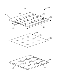
[00021] FIG. 1, is an exploded view of an exemplary layered three-
dimensional
(3D) microfluidic living cell array 100. The cell array 100 provides a
nanoscaffold
hydrogel that permits cells, such as cloned cancer or nonmalignant cells, to
grow in a
synthetic three-dimensional matrix. Cell array 100 comprises a first layer
101, a second
layer 102 and a third layer 103 that is disposed between the first layer 101
and the second
layer 102. In the embodiment depiCted, the third layer 103 is in contact with
both the
first layer 101 and the second layer 102. The first layer 101 comprises a
plurality of cell
culture channels 104 which, in the exemplary embodiment, includes a plurality
of cell
culture chambers 122. The third layer 103 comprises a filter membrane 110 with
a nest
of pores 112 that fluidly connect a cell culture channel 104 to a microfluidic
channel 108
of the second layer 102. The microfluidic channel 108 extends along
longitudinal
direction 106. The microfluidic channel 108 comprises a fluid inlet 114 at a
first end 116
of the second layer 102 and a fluid outlet 118 at a second end 120 of the
second layer
102. The first end 116 and the second end 120 are disposed on opposite ends of
the
second layer 102 and are spaced apart along longitudinal direction 106. The
fluid inlet
114 may be connected to, for example, a syringe pump for delivering fluids at
a
predetermined flow rate. The flow rate may be selected to approximate the flow
rate of
blood through a small blood vessel. In one embodiment, the flow velocity is
between
- 4 -
CA 02852950 2014-04-17
WO 2013/059755
PCT/US2012/061229
500-1000 microns per second. In another embodiment, the flow rate is between
100-800
microns per second. In yet another embodiment the flow rate is between 100-200
microns per second. The flow rate is the product of the flow velocity
multiplied by the
cross-sectional area of the channel.
[00022] Referring to FIG. 2, during operation cells are introduced into the
cell
culture channels 104 (e.g. introduced into the cell culture chambers 122). The
cell
culture channels 104 may be filled with a suitable media, such as a hydro gel
media. The
media provides a porous environment suitable for growing cells. Nutrients are
dissolved
or suspended in a liquid and introduced into the fluid inlet 114 at a
predetermined rate.
The fluid flows in direction of arrow 200 until it exits the fluid outlet 118.
The flow rate
through microfluidic channel 108 flows at a relatively high rate, compared to
the very
low flow rate through the second layer 102 and the low flow rate in the third
layer 103.
Advantageously this minimizes the shear stress cells experience in the cell
array to more
closely approximate an in vivo environment.
[00023] As shown in FIG. 2, a nest of pores 112 fluidly connect the
microfluidic
channel 108 to the cell culture channels 104. In the embodiment depicted, each
of nest of
pores 112 are arranged such that they are vertically stacked above a
corresponding cell
culture chamber 122 of the cell culture channel 104. Nutrients in the fluid
pass into the
cell culture channels 104 in the direction of arrow 202, limited by the size
of the pores
within the nest of pores 112. This is generally a diffusion-controlled
process. Once the
nutrients pass into the cell culture channels 104 they are transported in the
direction of
arrow 204. Other material, such as the waste products of the cells and excess
nutrients,
diffuse in the direction of arrow 206 where they rejoin the fluid in the
microfluidic
- 5 -
CA 02852950 2014-04-17
WO 2013/059755
PCT/US2012/061229
channel 108. These other materials are transported in the direction of arrow
200 where
they exit cell array 100 at fluid outlet 118.
[00024] The microfluidic dynamics of cell array 100 provides a three
dimensional
environment that closely approximates the environment experienced by a cell in
its native
(biological) environment. By mimicking the fluid dynamics provided by
arteriole, venule
and capillary systems, cells grown within the cell array 100 can be grown in a
fashion
that more closely matches native growth patterns. This makes it more likely
the cloned
cells will retain the biological characteristics (e.g. drug susceptibility) of
the cells, leading
to more accurate drug screening tests. FIG. 3A provides another view of the
microfluidic
dynamics of cell array 100.
[00025] FIG. 3A shows a microfluidic channel 308, a third layer 303 with
pores
312a, 312b and 312c. A cell culture channel 304 is also depicted. Fluid flows
quickly
through the microfluidic charmel 308 in the direction of arrow 300a. Due to
fluid
dynamics, the flow rate of the fluid proximate the walls of the microfluidic
channel 308 is
slower. See arrow 300b. A portion of the fluid passes through nest of pores
312a, 312b
and 312c, into the cell culture channel 304 and exits the pores to rejoin the
microfluidic
channel 308. Fluid dynamic calculations indicate the flow rate in the cell
culture channel
304 is, in one embodiment, about 0.1 micrometers per second, which corresponds
to the
interstitial flow rate in vivo. Wherein a cell culture channel, flow rate
through the nest of
pores 312a (the upstream pore) is relatively fast. Likewise, the flow rate
through nest of
pores 312c (the downstream pore) is also relatively fast. The flow rate
through nest of
pores 312b, which is between the upstream and downstream pore, is somewhat
slower.
The flow rate gradually changes with the nest of pores at the center of the
third layer 303
- 6 -
CA 02852950 2014-04-17
WO 2013/059755
PCT/US2012/061229
having the slowest flow rate. The flow rate through the nest of pores
increases as one
moves either upstream or downstream relative to the central nest.
[00026] The flow rate through the cell culture channel 304 is generally
fastest at
point 314b which is at the center of the cell culture channel 304. The flow
rates through
cell culture channel 304 decreases as one moves either upstream or downstream
from the
center of the cell culture channel 304. For example, fluid dynamic
calculations show the
flow rates at points 314a and 314b are relatively slow. The fluid dynamic
behavior
results in a subtle concentration gradient of material within the fluid.
Examples of two
such gradients are shown in FIG. 3B.
[00027] FIG. 3B schematically depicts the subtle concentration gradients
for a
nutrient (oxygen) and a waste product (carbon dioxide). The subtle
concentration
gradient confirms that the cell array can efficiently perform oxygen delivery
and carbon
dioxide removal even with subtle concentration gradients. The concentration of
oxygen
is relatively high at point 316a. As the fluid flows in the direction of arrow
318, a portion
of the oxygen migrates through the pores and is consumed by the cells. The
concentration of oxygen at point 316b is therefore lower than point 316a.
Modeling
suggests the concentration gradient in the microchambers is present, but
subtle (e.g. about
0.0003%) and that the vertical concentration gradient between the first layer
and the
second layer is sufficient for efficiency oxygen/carbon dioxide exchange. The
lowest
concentration of oxygen is at point 316d. The concentration of oxygen at point
316c is
similar to that of point 316b, due to a balancing of diffusion and flow rate.
In a similar
fashion, the concentration of carbon dioxide follows the same trend with the
opposite
direction. Carbon dioxide concentration is relatively low at point 316a. As
the fluid
- 7 -
CA 02852950 2014-04-17
WO 2013/059755
PCT/US2012/061229
flows in the direction of arrow 318, a portion of the carbon dioxide migrates
from the
cells through the pores and joins the fluid. The concentration of carbon
dioxide at point
316b is therefore higher than point 316a. The highest concentration of carbon
dioxide is
at point 316d. The concentration of carbon dioxide at point 316c is similar to
that of
point 316b, due to a balancing of diffusion and flow rate.
[00028] FIG. 4 is a detailed top view of an exemplary second layer 402. The
second layer 402 is formed of an opIically transparent material to facilitate
viewing of the
cellular samples as well as probing of the samples using microscopic
techniques. The
second layer 402 comprises a plurality of microfluidic channels 408 including
a first
microfluidic channel 408a and a second microfluidic channel 408b. The channels
extend
in a longitudinal direction 406. The first microfluidic channel 408a and the
second
microfluidic channel 408b are fluidly connected by a joining channel 424 at a
first end
416 which is opposite second end 420. When fluid is introduced to fluid inlet
414, the
fluid flows through joining channel 424 and into the first microfluidic
channel 408a and
the second microfluidic channel 408b. Excess fluid exits through fluid outlet
418. The
microfluidic channels 408 are vertically stacked above the pores of the third
layer 503.
See FIG. 5.
[00029] FIG. 5 is a depiction of an exemplary third layer 503. The third
layer 503
is formed of an optically transparent material. In the embodiment of FIG. 5,
the pores
513 are grouped into nests of pores 512. The pores 513 have a diameter
suitable to
control the rate of diffusion of material through the pores. The pores 513 may
have a
diameter of between about 10 micrometers and about 40 micrometers. For
example, in
one embodiment the pores 513 have a diameter of about 20 micrometers. The
nests of
- 8 -
CA 02852950 2014-04-17
WO 2013/059755
PCT/US2012/061229
pores 512 are arranged in a line that extends along longitudinal direction 406
so as to
vertically stack the pores 513 with the microfluidic channels 408 and fluidly
connect
them. The nests of pores 512 are also arranged to be vertically stacked above
corresponding cell culture chambers. In one embodiment, there is one nest of
pores 512
for each cell culture chamber (i.e. a one-to-one ratio).
[00030] FIG. 6 is a top view of an exemplary first layer 601. The first
layer 601 is
formed of an optically transparent material. The first layer 601 comprises a
plurality of
cell culture chambers 622 joined by cell culture channels 604. In the
embodiment
depicted there are twenty-four cell culture chambers 622 in a 4x6 array of
cell culture
chambers. Such an embodiment may be used with a third layer that has twenty-
four nests
of pores, each of which is vertically, stacked above a corresponding cell
culture chamber.
A wide variety of cell culture chamber configurations may be used. For
example, an 8x8
array of cell culture chambers may be used. In another embodiment, a 10x10
array is
used. The aforementioned arrays and merely examples. The cell array is highly
scalable
for use in high throughput drug scretn in a clinical or industrial setting. In
those depicted
embodiments where cell culture chambers are used, the chambers are circles
with a
diameter greater than the width of the cell culture channels. In one
embodiment, the cell
culture chambers are circles with a diameter between about 100 micrometers and
about
800 micrometers. In one embodiment, the cell culture chambers are circles with
a
diameter of about 770 micrometers. The width of the cell culture channels and
the
microfluidic channels corresponds to the width of blood vessels and is
generally several
hundred micrometers. This precise width may be adjusted depending on what
types of
blood vessels are being mimicked. In one embodiment, the width of the channels
is
- 9 -
between 50 microns and 500 microns. In another embodiment, shown in FIG. 7,
the first
layer 701 comprises a plurality of cell culture channels 704 that do not
include designated
cell culture chambers 122. Cellular growth occurs within cell culture channels
704.
[00031] FIG. 8 is a bisected side view of an exemplary cell array 800
comprising
first layer 801, second layer 802 and third layer 803. The first layer 801 has
a first
thickness 801a. The second layer 802 has a second thickness 802a. The third
layer 803
has a third thickness 803a. In the embodiment depicted, the first thickness
801a is greater
than the third thickness 803a but is less than the second thickness 802a. In
one
embodiment, the first thickness 801a is between 60 and 100 micrometers. In
another
embodiment, the first thickness 801a is between 70 and 90 micrometers. In one
embodiment, the second thickness 802a is about 130 micrometers, the third
thickness
803a is about 40 micrometers and the first thickness 801a is about 80
micrometers. By
providing a relatively thick second layer 802, a desirable flow rate is
maintained. By
controlling the thickness of third layer 803, the diffusion rate can be
controlled. The
thickness of the first layer 801 provides a three-dimensional volume within
which cells
can be grown. The relative thickness of first layer 801 impacts the
microfluidics of the
cell array.
[00032] In some embodiments, a first access port 900 is disposed at a
terminus of a
channel 902 that connects the channel 902 to the ambient environment. Fluid,
which may
contain samples, may be withdrawn through these access ports. Channel 902 may
be a
cell culture channel of the first layer or a microfluidic channel of the
second layer. In
those embodiments where the channel 902 is a microfluidic channel of the
second layer,
the access port can function as a fluid outlet where excess liquid is
expelled. In those
- 10 -
CA 2852950 2020-02-05
CA 02852950 2014-04-17
WO 2013/059755
PCT/US2012/061229
embodiments where the channel 902 is a cell culture channel, the access port
can be used
to selectively withdraw samples for subsequent testing. To access the content
of channel
902, one can form (as by drilling) a hole in the layer. Since the first access
port 900 has a
relatively large area, it is easier to properly position the hole than it
would be were first
access port 900 small. This is particularly advantageous considering the small
size of
many of the exemplary arrays. To avoid inadvertently drilling into channel
902, the first
access port 900 is spaced from the channel 902 by a path 904 that fluidly
connects the
access port 900 to the channel 902. To minimize the volume of fluid that
occupies the
path 904, the width of path 904 is narrower than the width of channel 902.
When a
second access port 906 is proximate the first access port 900, it can be
difficult to drill a
hole to access one port without inadvertently drilling into the other access
port. To
minimize this risk, second access port 906 is staggered relatively to the
first access port
900 by utilizing a second path 908 which has a length different from the
length of path
904. In the embodiment depicted, path 908 is shorter than path 904. In a
similar fashion,
one can access fluid inlet 910 by drilling a hole in the layer to expose the
fluid inlet 910
to the ambient environment.
[00033] In one embodiment, the first, second and third layers are formed of
an
optically transparent material to facilitate visual inspection of the cells as
well as permit
microscopic probing of the sample. Examples of suitable materials include
polydimethylsiloxane (PDMS) and other similar materials.
[00034] In one embodiment, the hydrogel is a peptide-based hydrogel sold
under
the brand name PURAMATRIXTm. This hydrogel is an exemplary peptide-based
hydrogel with over 99% water content that can self-assembly into 3D
interweaving
-11 -
CA 02852950 2014-04-17
WO 2013/059755
PCT/US2012/061229
nanofibers after a salt solution is added. Such a hydrogel provides pore size
ranges from
about 50 nm to about 200 nm. The peptide sequence may be chosen to promote
cell
attachment and migration (e.g. peptide RAD16-I).
[00035] In the embodiments depicted, a select number of channels are shown.
It
should be understood that other embodiments may use more channels or fewer
channels
and that such embodiments are contemplated for use with the present invention.
Additionally, the fluid inlets and fluid outlets are exchangeable. This
permits a different
number of drugs to be introduced. For example, two inlets may be used with
eight outlets
when two drugs are employed. As a further example, eight inlets with two
outlets may be
used when eight drugs are employed. The fluid inlets and fluid outlets are not
necessarily
at opposite ends of the cell array. Depending on the fluid pathway, the fluid
inlet and/or
fluid outlet may be positioned at another location.
[00036] An imaging method to detect dynamic signals from live cells
cultured in
the cellular array is may be used to monitor cell growth in real time. For
example,
fluorescence microscopy and z-direction slicing with a moving objective and an
on-stage
incubator may be used. Suitable equipment is commercially available and
includes the
Axio0bserver Z1 by Zeiss, Inc. Deconvolution software may be used to generate
clear
3D cell images from z-stack images. The system described herein permits real
time drug
mechanism studies, including drug kinetics with spatial resolutions in
apoptotic signaling
networks using a scalable 3D microfluidic platform.
[00037] Referring to FIG. 10, in one embodiment, the cell array is used in
a
combinatorial drug screening process. A variety of cellular samples may be
placed in a
cell array in which each sample is disposed in its own cell culture chamber to
form rows.
-12-
CA 02852950 2014-04-17
WO 2013/059755
PCT/US2012/061229
For example, a first type of cancer cell may be placed in first cell culture
chambers
1022a, 1023a while a second type of cancer cell is placed in second cell
culture chambers
1022b, 1023b. A select drug is screened by sending the drug, at a
predetermined
concentration, through a microfluidic channel. For example, a first drug is
introduced
into the array such that it contacts cell culture channel 1004a while a second
drug is
introduced into the array such that it contacts cell culture channel 1004b. In
the
embodiment of FIG. 10, the first layer and the second layer are orthogonal
with the
second layer shown in phantom. Because the rows of cancer cell types are
orthogonal to
the longitudinal direction of the cell culture channels, a wide variety of
drugs can be
screened against multiple cancer cell types. In one embodiment, microvalves
are
positioned in the cell culture channel between each of the cell culture
chambers. The
microvalves prevent two different drugs from cross contaminating the cell
culture
chambers. Suitable microvalves are known. See, for example, an article
entitled "A
high-throughput microfluidic real-time gene expression living cell array" by
King et al.
(Lab Chip; 2007 January; 7(1) 77-75). When the bottom layer is seeded with
cells, the
valves may be opened. After seeding, the valves may be closed. One of the
microfluidic
channels may be a drug-free fluid to function as a control.
[00038] One advantage of the technique described above is the ability of
the
system to microscopically monitor cell growth in real time as the cell culture
develops.
In one embodiment, the microscopic data is subjected to data mining to permit
the
screening process to be automated. Another advantage is the capability of
using the cell
array in personalized medicine. Tumor cells, and/or other types of cells, from
a particular
patient may be quickly subjected to a wide variety of drugs so that the most
effective
- 13 -
CA 02852950 2014-04-17
WO 2013/059755
PCT/US2012/061229
drug for that individual can be quickly identified.
[00039] The layers described in this specification may be formed according
to
conventional microfabrication techniques. Such techniques are employed in the
field of
micro-electro-mechanical systems (MEMS). For example, a silicon wafer may be
coated
with a layer of photoresist. A patterned mask is used to selectively protect
those areas of
the wafer which will be the channels or pores. Treatment with ultraviolet
light etches
those areas not protected by the mask to produce a master mold. The master
mold is
coated with a polymerizable mixture. Upon polymerization, the layers are
formed with
the appropriate patters or pores and separated from the mold.
[00040] While the invention has been described with reference to certain
embodiments, it will be understood by those skilled in the art that various
changes may
be made and equivalents may be substituted for elements thereof to adapt to
particular
situations without departing from the scope of the disclosure. Therefore, it
is intended
that the claims not be limited to the particular embodiments disclosed, but
that the claims
will include all embodiments falling within the scope and spirit of the
appended claims.
EXAMPLE 1
[00041] The device was tested by using food dyes. Liquid food dyes were
introduced to the fluid inlets of the second layer with syringes. The flow
with food colors
moved through microfluidic channels and at the same time the dye diffused from
the
second layer to the first layer by passing through the pores on the third
layer in 2.5
seconds. The diffusion time was estimated using a video capturing the complete
procedure of the food color experiment.
-14-
CA 02852950 2014-04-17
WO 2013/059755
PCT/US2012/061229
EXAMPLE 2
[00042] PC9 (non-small lung cancer) cells encapsulated in peptide hydrogel
were
cultured in the first layer for seven days. On day seven, calcein AM was
introduced in
the second layer to test the diffusion of the dye and viability of the cells.
Live cells
should be fluorescent green. Microscopic inspection showed that diffusion of
calcein
AM happens in seconds, and by fifty-two seconds all live cells become
fluorescent green.
EXAMPLE 3
[00043] A long term 3D cell culture for two weeks was also performed. PC9
cells
were dyed with long term green fluorescent cell tracker and encapsulated in
peptide
hydrogel. A syringe pump was used to deliver fresh medium continuously at
0.5microliters per minute in the second layer. Cells were imaged using an 10X
objective
with z-direction moving ability. Then a 3D image was reconstructed using z-
stack
images after deconvolution showing live cells.
EXAMPLE 4
[00044] In order to show our device is feasible to perform a structured co-
culture
between cancer cells and endothelial cells, PC9 were dyed with red
fluorescence cell
tracker (DIL), seeded and cultured in the first layer for several days,
followed by
microvascular endothelial cell seeding in the second layer without dye.
Microscopic
inspection showed that a structured co-culture was achieved successfully. This
experiment confirmed that not only micro-tumor arrays can be generated but
that tumor
- 15 -
CA 02852950 2014-04-17
WO 2013/059755
PCT/US2012/061229
microenvironments can also be mimicked that are similar to their in vivo
conditions (e.g.
tumors are surrounded by blood vessels without lymph vessels).
=
- 16 -