Note: Descriptions are shown in the official language in which they were submitted.
CA 02852971 2014-04-22
WO 2013/059878
PCT/AU2012/001312
1
REVERSE CIRCULATION HAMMER SPLINE ARRANGEMENT IMPROVEMENTS
FIELD OF THE INVENTION
The present invention relates a down-the-hole hammer drill. This invention has
particular application
to a reverse-circulation (RC) down-hole face sampling hammer drill, and for
illustrative purposes,
reference will be made to this application.
PRIORITY
This patent application claims priority from:
Australian Provisional Patent Application 2011904443, titled " RC HAMMER
SPLINE
ARRANGEMENT IMPROVEMENTS", and filed on 26 October 2011.
The entire content of this application is hereby incorporated by reference.
BACKGROUND OF THE INVENTION
A drill bit of a percussive down hole hammer (be it normal or reverse
circulation (RC)) is
conventionally provided with a bit body and splined shank. This shank locates
within a splined drive
sub, which in turn is threadably engaged to an end of a hammer barrel. The use
of the spline between
the drill bit and drive sub enables rotation of the drill bit withthe hammer
while at the same time
allowing longitudinal movement of the drill bit with respect to the hammer.
Examination of used RC bits very often indicates an uneven wear pattern of bit
inserts and bit body.
It is against this background that the problems and difficulties associated
therewith that the present
invention has been developed.
certain objects and advantages of the present invention will become apparent
from the following
description, taken in connection with the accompanying drawings, wherein, by
way of illustration and
example, an embodiment of the present invention is disclosed.
SUMMARY OF THE INVENTION
In one aspect, the invention may be said to reside in a percussive down hole
hammer comprising a
drill bit having a working face (or cutting face), the percussive down hole
hammer further comprising
CA 02852971 2014-04-22
WO 2013/059878
PCT/AU2012/001312
2
means for preferentially directing a fluid to at least one portion of the
cutting face in preference to
other portions of the cutting face to flush the cutting face.
In a further aspect, the invention may be said to reside in a percussive'down
hole hammer comprising
a drill bit having a cutting face and a means for delivering a fluid to the
cutting face, the means and the
cutting face being operatively complimentary for the purpose of flushing the
cutting face using the
=
fluid.
In one form, the fluid is a flushing fluid and the cutting face is cleaned by
the flushing of cuttings.
That is to say, delivery of fluid to the cutting face is tailored to the
design of the cutting face to
= improve flushing of the cutting face.
Air supply to a head of known down hole hammers is evenly distributed (i.e.
via flow through spline
channels in RC bits or flushing holes in conventional DTH bits), but because
the working/cutting (or
strike) face geometry is typically asymmetric, a considerable amount of air
escapes via the sample
tube and external annulus without affecting rock cuttings that are generated
during the fracturing
process. The immediate consequences are:
> Reduction of drilling performance in the form of reduced penetration rate
because of re-
crushing of rock debris instead of cutting removal;
> Reduction of drilling efficiency due to an increase of required
compressor power;
> Increase of bit wear due to insufficient bit-rock face cleaning (re-crushing
of rock debris).
In one form of the present invention then, the means for preferentially
directing fluid to the cutting
face preferentially directs fluid to portions of the cutting face having
increased flushing needs.
In one form, the means for preferentially directing fluid to the cutting face
directs more fluid to
portions of the cutting face having increased flushing needs than other
portions of the cutting face.
The load on a cutting face insert is the result of insert spacing combined
with the fluid flow at the
cutting face. If the fluid at the rock-cutting face interface is properly
directed, then the load on the
individual inserts reduces, which ultimately leads to an increase in drilling
performance.
=
=
CA 02852971 2014-04-22
WO 2013/059878
PCT/AU2012/001312
3
In one form, the means for preferentially directing fluid to the cutting face
comprises at least one fluid
passage (or channel).
In one form, the means for preferentially directing fluid to 'the cutting face
comprises at least two
passages (or channels), where each channel directs fluid to a different
portion of the cutting face, and
at least one channel delivers a greater. flow rate of fluid than the other.
In one form, the percussive down hole hammer comprises a splined drive sub
comprising driving
splines abutting driven splines on a shank of the drill bit.
In a further aspect, the invention may be said to reside in a drill bit for
the above described percussive
down hole hammer.
In yet a further aspect, the invention may be said to reside in a drive sub
for the above described
percussive down hole hammer.
In one form, the hammer is an RC hammer, and there is a channel defined
between adjacent pairs of
abutting splines, and fluid is supplied via the or each channel.
The operating principle of RC hammers makes this invention particularly
suitable for these. The main
flow direction at the working (i.e. bit) face is from outside to inside, i.e.
from the outer of the cutting
face diameter inwards towards the hammer axis. The air distribution around the
bit head is strongly
affected by the flow field upstream of the cutting face and therefore offers
potential to optimize the
local supply of the flushing media to inserts with increased need for debris
removal.
In one form, not all channels are of equal dimensions.
In one form, not all channels are equi-spaced around the circumference of the
drill bit and drive sub.
In one form, at least one channel is larger than others.
In one form, at least one channel is wider than others.
In one form, not all splines are of equal dimensions.
In one form, not all splines are equi-spaced around the circumference of the
drill bit and drive sub.
CA 02852971 2014-04-22
WO 2013/059878
PCT/AU2012/001312
4
In one form, at least one spline is larger than others.
In one form, at least one spline is wider than others.
In one form, the splines are not distributed symmetrically around their
respective diameters.
. In one form, the pitch angle between two neighbouring splines varies as a
function of angle on the
circumference.
In one form, a variation of the spline pitch angle and/or spline thickness of
driving and/or driven
splines may be limited to one or more sectors of the circumference or be
continuous.
In one form, the spline variations are incorporated in a way that the parts
cannot be misassembled (e.g.
relative position of drive-sub to shank).
In one form, where the basic geometry does not prevent such mis-assembly, then
features such as
notches or shoulders are used and positioned so that,these prevent mis-
assembly.
In one form, to either side of the drill bit there are two driven splines
(i.e. two pairs of these) spaced so
that the width between these two splines is greater than the width between any
other two splines
around the drill bit.
In one form, to either side of the drive-sub there are two driving splines
(i.e. two pairs of these) spaced
so that the width between these two splines is greater than the width between
any other two splines
around the drive-sub. =
In one form, one of each of the driving splines in these two pairs is
considerably wider than the
remainder of the driving splines.
In one form, the larger channels are primary channels, and smaller channels
are secondary channels.
In one form, the primary channels direct fluid to sample holes in the cutting
face.
In one form, in an alternative, the primary channels direct fluid
substantially orthogonal to sample
holes in the cutting face. =
CA 02852971 2014-04-22
WO 2013/059878 PCT/AU2012/001312
=
For normal percussive down hole hammers the means for preferentially directing
fluid to the cutting
face comprises more than one channel having an outlet in the cutting face.
In one form, each outlet is a hole, and hole diameters are not constant but
varying in size.
5
In a further aspect, the invention may be said to reside in a means for
cleaning a cutting face of a
percussive down hole hammer comprising a drill bit and a drive sub, wherein
said means preferentially
directs a fluid to at least one portion of the cutting face in preference to
other portions of the cutting
face.
In a further aspect, the invention may be said to reside in a down-the-hole
hammer comprising a drill
bit and a drive sub, the drill bit comprising a shank, and a head having a
cutting face, the drive sub
surrounding at least a portion of the shank and cooperating with the drill bit
to form fluid passages
extending lengthwise along the shank to direct fluid to the cutting face to
flush this, where each
passage directs fluid to a different portion of the cutting face, and at least
one passage is adapted to
deliver a greater flow rate of fluid than the others, thereby directing fluid
to at least one portion of the
cutting face in preference to other portions thereof.
In a further aspect, the invention may be said to reside in a drill bit for a
down-the-hole hammer
comprising a shank, a head having a cutting face, and fluid passages extending
lengthwise along the
shank to direct fluid to the cutting face to flush this, where each passage
directs fluid to a different
portion of the cutting face, and at least one passage is adapted to deliver a
greater flow rate of fluid
than the others, thereby directing fluid to at least one portion of the
cutting face in preference to other
=
portions thereof.
In a further aspect, the invention may be said to reside in a drive sub for a
down-the-hole hammer
having a drill bit comprising a shank, and a head having a cutting face, the
drive sub surrounding at
least a portion of the shank and cooperating with the drill bit to form fluid
passages extending
lengthwise along the shank to direct fluid to the cutting face to flush this,
where each passage directs
fluid to a different portion of the cutting face, and at least one passage is
adapted to deliver a greater
flow rate of fluid than the others, thereby directing fluid to at least one
portion of the cutting face in
preference to other portions thereof.
A detailed description of one or more embodiments of the invention is provided
below along with
accompanying figures that illustrate by way of example the principles of the
invention. While the
invention is described in connection with such embodiments, it should be
understood that the
invention is not limited to any embodiment. On the contrary, the scope of the
invention is limited only
by the appended claims and the invention encompasses numerous alternatives,
modifications and
CA 02852971 2014-04-22
WO 2013/059878
PCT/AU2012/001312
6
equivalents. For the purpose of example, numerous specific details are set
forth in the following
description in order to provide a thorough understanding of the present
invention.
The present invention may be practiced according to the claims without some or
all of these specific
details. For the purpose of clarity, technical material that is known in the
technical fields related to the
invention has not been described in detail so that the present invention is
not unnecessarily obscured.
= BRIEF DESCRIPTION OF THE DRAWINGS
For a better understanding of this disclosure it will now be described with
respect to one or more
exemplary embodiments, which shall be described herein with the assistance of
drawings wherein:
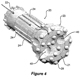
Figure 1 is a perspective view of a drive sub;
Figure 2 is an end view of the drive sub of Figure 1;
Figures 3 and 4 are perspective views of a drill bit;
Figure 5 is a perspective view of the assembled drive-sub and drill bit;
Figure 6 is a cross-sectional view, taken lengthwise, through the drive-sub
and drill bit of Figure 5;
and
= Figure 7 is a cross-sectional view, taken crosswise, through the drive-
sub and drill bit of Figure 5.
In the following description, like reference characters designate like or
corresponding parts throughout
the several views of the drawings.
DESCRIPTION OF A PREFERRED EMBODIMENT
Referring now to Figure 1, where there is illustrated drive-sub 10 for a
pneumatically operated (i.e. in
which air is the working and flushing fluid) percussive down hole RC hammer
that combines the
hammer (or hitting) action with the turning action of rotary drilling. This
drive sub 10 comprises an
annular sleeve 12 with an array of spaced apart, inwardly directed driving
splines 14.
Referring now to Figures 3 and 4, where there is further illustrated a drill
bit 20 for the RC hammer,
the drill bit 20 comprising a shank 22 and a drill bit head 23, the drill bit
head 23 having a cutting face
21 with carbide inserts 29. The shank 22 comprises a number of outwardly
directed driven splines 24,.
which are so spaced and numbered as to form, with the driving splines 14,
pairs of splines having
=
=
CA 02852971 2014-04-22
WO 2013/059878
PCT/AU2012/001312
7
abutting cutting faces when the bit 20 is inserted into the drive sub 10 (see
Figure 6). A channel 25 is
defined between adjacent pairs of abutting splines 14 and 24 (see Figure 7).
In use, the driving splines 14 act against the driven splines 24 to drive
rotation of the drill bit 20 while
permitting the drill bit 20 to move longitudinally (under the effect of the
hammer), with respect to the
drive-sub 10.
With reference to Figure 7, it can be seen that to either side of the drill
bit 20 there are two driven
splines 24a and 24b (i.e. two pairs of these) spaced so that the width between
these two driven splines
24a and 24b is greater than the width between any other two splines 24 around
the shank 22 of the drill
bit 20.
To either side of the drive-sub 10 there are two driving splines 14a and 14b
(i.e. two pairs of these)
spaced so that the width between these two splines 14a and 14b is greater than
the width between any
other two splines 14 around the drive-sub 10. One of each of the driving
splines 14a in these two pairs
is considerably wider than the remainder of the driving splines 14.
When the drive-sub 10 and drill bit 20 are assembled the two widest driving
splines 14a locate
between the most adjacently distant driven splines 24a and 24b so as to define
between them a pair of
passages (or channels) 25a which are larger (i.e. these are primary channels)
than any of the other
channels 25 (i.e. secondary channels) defined between adjacent pairs of
abutting splines 14 and 24.
=
The mass flow rate of air directed down through the channels is not the same
for each channel, but a
function of the channel size, so a greater mass flow rate of air is passed
through the primary channels
25a than is passed through the secondary channels 25.
By guiding the flushing air unequally around the shank 22 and to the perimeter
of the head 23 of the
bit 20, it is possible to direct air to areas of the cutting face 21 with
increased flushing needs, such as
around inserts 29 under high loads (i.e. critical inserts) and then to the
inlets 40 for the "inner tube" 42,
which returns the air (which now carries the entrained flushed cuttings) to
the surface. If the fluid at
the rock-cutting face 21 interface is properly directed by complimentary
positioning of the primary
channels .25a relative to the critical inserts, then the load on inserts 29
reduces, which ultimately leads
to an increase in drilling performance.
Any machining method may be utilised for realizing these channels. Naturally,
methods which are cost
effective are given priority over machining procedures that require long
machining times or pose
otherwise special requirements on the manufacturing process .
CA 02852971 2014-04-22
WO 2013/059878
PCT/AU2012/001312
8
Throughout the specification and the claims that follow, unless the context
requires otherwise, the
words "comprise" and "include" and variations such as "comprising" and
"including" will be
understood to imply the inclusion of a stated integer or group of integers,
but not the exclusion of any
other integer or group of integers.
The reference to any prior art in this specification is not, and should not be
taken as, an
acknowledgement of any form of suggestion that such prior art forms part of
the common general
knowledge.
It will be appreciated by those skilled in the art that the invention is not
restricted in its use to the
particular application described. Neither is the present invention restricted
in its preferred embodiment
with regard to the particular elements and/or features described or depicted
herein. It will be
appreciated that various modifications can be made without departing from the
principles of the
invention. Therefore, the invention should be understood to include all such
modifications in its scope.