Note: Descriptions are shown in the official language in which they were submitted.
CA 02852972 2014-01-31
P507.500-000
POLYCRYSTALLINE DIAMOND COMPACT WITH INCREASED IMPACT
RESISTANCE
BACKGROUND OF INVENTION
The present invention relates generally to polycrystalline diamond (PCD) and,
more specifically, to method of strengthening PCD compacts.
Polycrystalline diamond (PCD) materials are formed by combining diamond
grains with a suitable catalyzing material under high pressure and high
temperature
conditions. Under such conditions, the catalyzing material promotes diamond-to-
diamond
bonding between the diamond grains. As a result, a PCD structure is formed.
The
resulting PCD structure has enhanced wear resistance and hardness
characteristics that
make the PCD structure useful in oil and gas drilling cutters and other
applications.
Catalyzing material is any material with the ability to help form bonds
between adjacent
diamond crystals. Examples of catalyzing material include but are not limited
to cobalt,
iron, and nickel.
A catalyzing material that is often used in PCD is cobalt. PCD typically
comprises
from 85% to 95% by volume diamond with catalyzing material, other elements,
and void
space comprising the remaining volume. The catalyzing material and other
elements are
found in the voids that exist between the bonded diamond grains. The
catalyzing material
facilitates diamond-to-diamond bonds between diamond grains in the PCD.
Diamond to
catalyzing material bonds are also formed under high pressure and high
temperature.
As a traditional PCD tool or compact is used in abrasive applications, such as
degrading a drilling formation, heat is generated at the working surface of
the PCD
compact where the PCD compact contacts the drilling formation. Heat causes the
catalyzing material and the diamond grains in the PCD compact to expand at a
rate
consistent with their respective rates of thermal expansion. Often, the
coefficient of
thermal expansion of the catalyzing material is higher than the coefficient of
thermal
expansion of the diamond. As a result, the catalyzing material expands at a
faster rate
than the diamond grains. Consequently, the catalyzing material pushes on the
diamond
grains as they expand, which puts strain on the diamond-to-diamond bonds.
Further,
since the catalyzing material can also be bonded to the diamond grains, the
catalyzing
material also pulls on the diamond grains as they thermally expand, placing
additional
strain on the diamond-to-diamond bonds. If the strain on the diamond-to-
diamond bonds
is sufficient enough, the diamond-to-diamond bonds will break, resulting in
thermal
1
CA 02852972 2014-01-31
degradation of the PCD compact particularly when temperature begins to exceed
600 C
at the working surface. Common results of such thermal degradation in a
traditional PCD
compact include micro-cracks, cracks, chips, fractures, delaminating, and
dulling of the
cutting edge. Catastrophic breakage of the PCD can also occur.
One technique that has been used to prevent the thermal degradation issues
from
occurring in the PCD material during such drilling applications is to
permanently remove
substantially all the catalyzing material from just the volume adjacent the
working surface
of the PCD material. Thus, as the PCD material's working surface heats up
there is no
catalyzing material in the PCD material's surface to expand at a different
rate than the
diamond grains. However, the permanent removal of substantially all the
catalyzing
material from the volume adjacent the PCD material's working surface creates
void space
that can weaken the overall toughness and impact resistance of the cutter.
SUMMARY
In one aspect, a polycrystalline diamond (PCD) with diamond grains includes a
first zone of the diamond grains and a second zone of the diamond grains. The
first zone
forms a working surface and a first catalyzing material is disposed within
voids of the
diamond grains in the first zone. A second catalyzing material is bonded to
the diamond
grains disposed in the second zone. The first catalyzing material in the first
zone is
connected to the diamond grains disposed in the first zone less intimately
than the second
catalyzing material is bonded to the diamond grains in the second zone.
BRIEF DESCRIPTION OF THE DRAWINGS
The accompanying drawings illustrate various examples of the principles
described herein and are a part of the specification. The illustrated examples
are merely
examples and do not limit the scope of the claims.
Fig. la is a cross sectional diagram of an example of a PCD compact according
to
the principles described herein.
Fig. lb is a chart of an example of the constituents in a first zone and a
second
zone according to the principles described herein.
Fig. lc is a graph of an example of the constituents in a first zone and a
second
zone according to the principles described herein.
Fig. 2 is a cross sectional diagram of an example of a PCD compact according
to
the principles described herein.
Fig. 3 is a diagram of an example of a process for manufacturing a PCD compact
according to the principles described herein.
2
CA 02852972 2014-01-31
Fig. 4a is a diagram of an example of a process for manufacturing a PCD
compact
according to the principles described herein.
Fig. 4b is a diagram of an example of a process for manufacturing a PCD
compact
according to the principles described herein.
Fig. 5 is a cross sectional diagram of an example of a PCD compact according
to
the principles described herein.
Fig. 6 is a cross sectional diagram of an example of a PCD compact according
to
the principles described herein.
Fig. 7 is a cross sectional diagram of an example of a PCD compact according
to
the principles described herein.
Fig. 8A is a cross sectional diagram of an example of the PCD compact
according
to the principles described herein.
Fig 8B is an example of method for forming a PCD compact according to the
principles described herein.
DETAILED DESCRIPTION
In general, the principles described herein provide a PCD compact that is
resistant
to the thermal degradation issues experienced by many traditional PCD compacts
and
cutters while maintaining a high toughness and impact resistance. The
principles
described herein include at least a first zone and a second zone. The first
zone forms a
working surface and a volume adjacent to the working surface of the PCD
compact
containing a catalyzing material. The catalyzing material in the first zone is
less
intimately connected to the diamond than the catalyzing material in a second
zone. The
catalyzing material in the second zone is bonded to diamond that is adjacent a
cemented
metal carbide substrate.
In the following description, for purposes of explanation, numerous specific
details are set forth in order to provide a thorough understanding of the
present systems
and methods. It will be apparent, however, to one skilled in the art that the
present
apparatus, systems, and methods can be practiced without these specific
details.
Reference in the specification to "an example" or similar language means that
a particular
feature, structure, or characteristic described is included in at least that
one example, but
not necessarily in other examples.
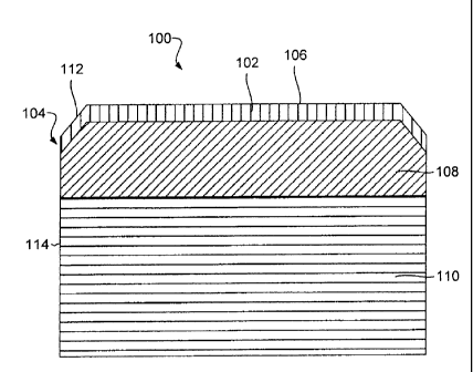
Fig. 1 a is a cross sectional diagram of an example of a PCD compact (100)
according to the principles described herein. In this example, the PCD compact
(100) can
be a cutter that is well suited for attachment to drill bits used for oil and
gas drilling,
3
CA 02852972 2014-01-31
mining, geothermal applications, excavating, other rock or subterranean
degradation
applications, or combinations thereof. The PCD compact (100) has a first zone
(102) of
PCD (104) that forms a portion of the compact's working surface (106) and a
second
zone (108) of PCD (104) that is adjacent to a cemented metal carbide substrate
(110). In
the example of Fig. la, the working surface (106) of the PCD compact (100) is
flat with a
beveled cutting edge (112). The first zone (102) spans the entire working
surface (106)
and includes all of the beveled edge (112). In other examples, the first zone
(102) can
include a region just around the beveled edge (112) or another appropriate
region that is
less than the entire working surface (106). Also, the first zone (102) can
extend to a
periphery (114) of the PCD compact (100).
The cemented metal carbide substrate (110) is bonded to the second zone (108)
of
the PCD (104) in a high pressure, high temperature (HPHT) press. The cemented
metal
carbide substrate (110) can be a tungsten carbide substrate or can have other
appropriate
constituents known in the art to provide an adequate base for the PCD (104)
and for
bonding the PCD compact (100) to tools such as drill bits, reamers, picks,
drums,
bearings and the like. While sintering in the HPHT press, catalyzing material,
such as
cobalt, can be drawn out of the cemented metal carbide substrate (110) into
the initially
unbonded diamond grains of PCD (104) in both the second zone (108) and the
first zone
(102). As the catalyzing material enters into the unbonded diamond grains of
the second
zone (108) and the first zone (102), the catalyzing material catalyzes diamond-
to-diamond
bonds between the diamond grains, thereby forming a volume of sintered PCD
(104). In
some examples, the catalyzing material can be added directly to the unbonded
diamond
grains prior to the HPHT process to promote sintering. In other examples,
mechanisms
such as barriers positioned to impede a flow of catalyzing material from the
cemented
metal carbide substrate (110) into the volume of unbonded diamond grains can
be
employed to control the amount of catalyzing material that enters the unbonded
diamond
grains during sintering. Regardless of how the catalyzing material gets into
the unbonded
diamond grains, the catalyzing material is useful for lowering the
temperatures and
pressures needed to sinter the PCD (104). After the sintering process, the
catalyzing
material remains in the sintered PCD (104) in voids formed between the diamond
grains.
In addition to the diamond-to-diamond bonds, the catalyzing material forms
diamond-to-
catalyzing material bonds as well.
To reduce or eliminate the thermal expansion and toughness issues caused by
the
catalyzing material or permanent removal of catalyzing material as described
above in the
4
CA 02852972 2014-01-31
discussion of the prior art, the PCD (104) undergoes a treatment where
catalyzing
material in the first zone (102) and the working surface (106) is less
intimately connected
to diamond in zone (102) compared to zone (108).
Less intimately connected can mcan that at least a portion of the catalyzing
material in the first zone (102) is not bonded to diamond grains disposed
within the first
zone (102). Less intimately connected can also mean the catalyzing material in
the first
zone is substantially unbonded to the diamond grains in the first zone (102),
or that the
bonds between the catalyzing material and the diamond grains in the first zone
(102) are
weaker than the bonds found in the second zone (108). The catalyzing material
in the first
zone (102) remains unaltered by alloying, crystal structure changes, phase
changes,
mechanical working, thermal treatment or any other such method that results in
altering
the catalyzing ability of the catalyzing material.
During heat generating applications, such less intimately connected catalyzing
material in the first zone (102) produces less strain in the PCD compact (100)
compared
to traditional PCD compacts containing intimately connected catalyzing
material in the
first zone (102), and also provides more structure and strength than
traditional PCD
compacts in which substantially all the catalyzing material has been
permanently
removed from volume (102). As such, when the catalyzing material expands
within the
first zone (102) of the PCD (104), the catalyzing material can expand and move
within
the voids without pulling and pushing on the diamond grains. This
significantly reduces
the residual stress in the PCD (104), thereby reducing thermally induced
degradation of
the PCD (104) and increasing the service life of PCD compact (100).
The process resulting in less intimately connected catalyzing material in the
first
zone (102) can include a process or method that does not cause diamond-to-
catalyzing
material bonds to form. A non-exhaustive list of methods include but is not
limited to
chemical vapor deposition, metal organic vapour phase epitaxy, electrostatic
spray
assisted vapour deposition (ESAVD), physical vapor deposition, cathodic arc
deposition,
electroless nickel plating or electroless cobalt plating, electron beam
physical vapor
deposition (EBPVD), ion plating or implantation, ion beam assisted deposition
(IBAD),
magnetron sputtering, pulsed laser deposition, sputter deposition, vacuum
deposition,
vacuum evaporation, evaporation (deposition), anodizing, conversion coating,
chromate
conversion coating, plasma metal coating, plasma electrolytic oxidation,
phosphate
coating, ion beam mixing, pickled and oiled plate steel coating, electroless
plating,
electroplating or electro injection, sol-gelling, plasma spraying, thermal
spraying, plasma
5
CA 02852972 2014-01-31
transferred wire arc thermal spraying, thermal diffusion, other appropriate
methods, or
combinations thereof.
A chemical vapor deposition method can involve suspending catalyzing material
in gas that causes the catalyzing material to be deposited in the voids
between the
diamond grains in the first zone (102). In some examples, this process can use
cobalt as
the catalyzing material.
An electrolysis, electroless, or electroplating process can be used in
conjunction
with a vacuum system, magnetic system, ultrasonic agitation, or other
mechanisms. The
vacuum system can assist in getting a solution containing an electrically
conductive
catalyzing material that is suspended in fluid into the first zone (102)
sufficient to
establish electrical connectivity to carry out the process. A capillary effect
can also be
sufficient to move fluid from the working surface (106) to a depth with
sufficient
catalyzing material to establish electrical connectivity. However, this
process cannot
form diamond-to-catalyzing material bonding for catalyzing material such as
cobalt
because such cobalt-to-diamond chemical reactions typically occur at a high
temperature
(approximately 1300 degrees Celsius).
Electrolysis can be used to create less intimately connected cobalt-to-diamond
connections. First, the cobalt or other type of catalyzing material can be
removed or
catalyzing material and diamond bonds broken with electrolysis, and then less
intimately
connected catalyzing material can be reinserted or packed into the voids of
volume (102)
by reversing the polarity of the voltage. In such an example, less intimately
connected
catalyzing material fills the voids in the first zone (102) of the PCD (104)
and thus
increases the strength of the PCD compact (100).
Adding some kinds of catalyzing material into the first zone (102) of the PCD
(104), such as cobalt, can be added in solution. Such solutions can be used
with or
without the aid of electrolysis. The solution could be silicon, liquid glass,
another suitable
solution, or combinations thereof. The solution can fill the voids formed
between the
diamond grains via a capillary effect. The solution can bc pushed into the
voids using
vacuum or cycling vacuum, atmospheric pressure, positive pressure, other
mechanisms,
or combinations thereof. If liquid glass is utilized as part of the solution,
the solution
must be raised to a temperature sufficient to form liquid glass (approximately
400 degrees
Celsius).
For plasma spray coatings or sputter coating, the catalyzing material, such as
cobalt, can be sprayed on the working surface (106) and allowed to seep into
the void
6
CA 02852972 2014-01-31
spaces disposed within the first zone (102). For electroless cobalt (or
nickel) plating, the
process causes the catalyzing material to penetrate the working surface (106)
to a desired
depth.
The processes used to add the catalyzing material into the first zone (102)
can be
accomplished at a relatively low pressure. For example, such a process can
occur at a
pressure lower than the pressures used to sinter diamond in a HTHP press. Such
lower
pressures can be at pressures that are less than a thousand pressure pounds
per square inch
(psi), less than five hundred psi, less than a hundred psi, at approximately
atmospheric
pressure, or less than atmospheric pressure.
Further, the processes used to enable less intimately connected catalyzing
material
in the first zone (102) can be accomplished at a temperature that is too low
to cause a
diamond-to-catalyzing material bond. Often cobalt, a suitable type of
catalyzing material,
reacts with diamond at a temperature around 1300 degrees Celsius. Thus, for
processes
used to produce a first zone (102) with less intimately connected catalyzing
material,
cobalt, the process occurs at a temperature less than 1300 degrees Celsius. In
other
examples, the temperature can be less than one thousand degrees Celsius, less
than five
hundred degrees Celsius, less than a hundred degrees Celsius, at room
temperature, or
less than room temperature.
Regardless of the method for producing a first zone (102) with less intimately
connected catalyzing material, the catalyzing material in the first zone (102)
puts less
strain on the diamond-to-diamond bonds because the catalyzing material has
more room
to move within the voids found within the first zone (102) than the catalyzing
material in
the second zone (108). As a result, the overall PCD compact (100) exhibits an
increased
amount of thermal stability and increased impact resistance.
The catalyzing material in the first zone (102) can be equal to the amount of
catalyzing material in the second zone (108). In some examples, the amount of
catalyzing
material in the first zone (102) is less than the amount of catalyzing
material in the second
zone (108). Further, the concentration of catalyzing material in the first
zone (102) can be
greater than the catalyzing material in the second zone (108).
Also, the catalyzing material in the first zone (102) can occupy less than the
entirety of the volume of the first zone (102). In such an example, the first
zone (102) can
include a first sub-portion that contains the less intimately connected
catalyzing material
and a second sub-portion that has little or no catalyzing material. Such a
second sub-
portion can be formed deeper in the first zone (102) than the first sub-
portion, and the
7
CA 02852972 2014-01-31
first sub-portion can include the working surface (106) and area directly
adjacent to the
working surface (106).
In some examples, zone (102) contains a different catalyzing material than in
zone
(108). In other examples zone (102) contains the same catalyzing material as
in zone
(108) with the only difference being that the catalyzing material in zone
(102) is less
intimately connected to diamond than in zone (108). Other material could also
be added
into the first zone (102) at low temperature and pressure including transition
elements
such as tungsten, tantalum, niobium, titanium, or other similar transition
element. Some
of these transition elements have lower thermal expansion than cobalt and also
have the
ability to improve the impact toughness of the PCD compact (100) when inserted
into the
void space of the first zone (102).
In some examples within the scope of the invention, the diamond-to-catalyzing
material bonds that were formed during the HTHP process in the first zone
(102) are
broken in situ. As a result, the catalyzing material in the first zone (102)
is free to move
and thermally expand in the voids of the first zone (102) of the PCD (104).
Fig. lb is a chart (140) of an example of the constituents in the first zone
(102)
and the second zone (108) of the PCD compact (100) that was tested in a
drilling
application according to the principles described herein. The PCD compact
(100) was a
13mm diameter round shear cutter. The first zone (102) spanned the entire
length of the
cutter and included the beveled edge (112) of the PCD (104). The depth of the
first zone
(102) ranged from about 200 microns to 225 microns from the working surface
(106) of
the PCD (104). One of the PCD compacts (100) used in the drilling test was
further
analyzed, the results of which are disclosed in the chart (140) of Fig. lb.
The chart (140)
includes a first zone (142) that extends from the working surface to a depth
of
approximately 220 microns and a second zone (144) that extends from the first
zone (142)
to the tungsten carbide substrate of the PCD compact (100). The first zone
(142) includes
an element column (146) and a weight percent column (148). The second zone
(144)
includes another element column (150) and a weight percent column (152). These
amounts were determined through analysis with a scanning electron microscope.
The chart (140) indicates that the constituents of the first zone (142)
include 88.64
weight percent of carbon, which is the diamond grains. Another 8.34 weight
percent was
oxygen. The catalyzing material in the first zone (142) includes 0.07 weight
percent of
iron, 2.41 weight percent of cobalt, and 0.55 weight percent of tungsten. The
chart (140)
indicates that the constituents of the second zone (144) include 83.06 weight
percent of
8
CA 02852972 2014-01-31
carbon and 5.35 weight percent of oxygen. The catalyzing material in the
second zone
(144) includes 0.10 weight percent of iron, 8.58 weight percent of cobalt, and
2.92 weight
percent of tungsten.
Fig. I b is a chart (140) that shows the tested PCD compact (100) had a
combined
average catalyzing material amount of about 3 weight percent in the first zone
(142) while
the second zone (144) included a average of 12.5 weight percent of catalyzing
material.
The first zone included less catalyzing material than the second zone. Further
following
the process, the cobalt in the first zone (142) is in the voids of the first
zone (142) under
temperature and pressure conditions such that the catalyzing material in the
first zone
(132) is less intimately connected to diamond grains than catalyzing material
in the
second zone (144).
Fig. lc is a graph (160) of an example of the constituents in the first zone
(142)
and the second zone (144) of 'the same PCD compact (100) that was described
above in
the chart (140) of Fig. lb. The y-axis (162) represents weight percent, and
the x-axis
(164) represents a distance from the working surface in microns. The dashed
line (166)
represents cobalt and the solid line (168) represents tungsten. The graph
(160) shows that
a greater deposit of cobalt is found near the working surface of the PCD
compact (100),
which starts to decline at about 60 microns. The cobalt concentration dips to
just below 2
weight percent at about 140 microns until about 200 microns where the first
zone (142)
ends and the second zone (144) begins. While the chart (140) and graph (160)
above
refer to specific weight percentages and distributions for a specific example,
any weight
percentages and distributions can be used in accordance with the principles
described
herein.
In some experiments, intimately connected catalyzing material, cobalt, was
depleted from the first zone through a standard acidizing procedure, as
described in U.S.
Patent No. 4,224,380. In other experiments an electro-plating process was
utilized to
deplete intimately connected catalyzing material. Less intimately connected
catalyzing
material, cobalt, was added into the voids of the first zone (102) utilizing
an electroplating
process. For example, the PCD compact (100) was submerged into a
supersaturated
ammonium cobalt(II) sulfate hexahydrate, 98%, solution. While specific
reference is
made to a particular type of solution, other solutions in varying proportions
were utilized
in some experiments such as combinations of cobalt/sodium sulfate and
cobalt/sodium
chloride or calcium cobalt and calcium hydroxide. In these examples, boric
acid, sulfuric
acid or other acids can be utilized as a buffer to control PH level during the
process.
9
CA 02852972 2014-01-31
In a similar fashion, other solutions can be utilized resulting in other
catalyzing
materials in the void space of the first zone (102) of the PCD (104). For
example,
experiments were conducted to inject catalyzing material, nickel, into the
void space. In
these experiments, varying combinations of solutions and varying proportions
of nickel
(II) sulfate hexahydrate, nickel chloride, ammonium chloride, boric acid, zinc
sulfate,
sodium thiocyanate were utilized as the fluid medium in the process to inject
nickel into
the void space. Fluid is added during the process to maintain a constant level
replacing
fluid that evaporates.
Several methods were used to prepare the PCD (104) and assist with the process
resulting in cobalt or another catalyzing material in the first zone (102)
that is less
intimately connected to diamond than catalyzing material in the second zone
(108). Those
methods of pretreatment and methods used during the treatment process include
but are
not limited to ultrasonic cleaning the PCD (104) in an acetone solution and/or
a water and
surfactant solution. Ultrasonic stimulation can also be utilized during the
injection process
of the catalyzing material. The PCD (104) can also be placed in a chamber
while in the
solution at a pressure less than atmospheric pressure before and/or during the
catalyzing
material injection process. The pressure can be cycled on a vacuum from
atmospheric to
less than atmospheric to aid in pulling the solution and catalyzing material
into the void
space. A magnetic field can also be utilized to assist in pulling the
catalyzing material
into the void space.
The catalyzing material injection process can be a multi-step or continuous
process. For example an electro-plating process can be conducted for a period
of time
followed by a thermal diffusion process whereby the PCD (104) is subjected for
a period
of time to a temperature of approximately 250 degrees Celsius, and then the
electro-
plating process can be conducted again for a period of time. The thermal
diffusion
process can range in temperature from 200 degrees Celsius to 600 degrees
Celsius. In any
event, the thermal diffusion process is performed at a temperature and
pressure below that
in which the catalyzing material forms bonds with the diamond. In one
experiment, a
lmm thick cobalt plate was oriented approximately 5mm from the working surface
(106)
of the PCD compact (100). In other experiments, the distance of a cobalt or
nickel plate
from the working surface (106) of the PCD compact (100) ranged from 2 mm to 15
mm.
The positive output of a DC power supply can be attached to the cobalt or
nickel
plate to serve as the anode. The negative output of a DC power supply can be
attached to
the cemented metal carbide substrate (110) connected to the PCD (104) and
serves as the
CA 02852972 2014-01-31
cathode. During an intimately connected cobalt removal process, the current
flow is
reversed from the current flow of less intimately connected cobalt injection
process. The
DC power supply can be set to deliver a constant direct current or can be set
to pulse on
and off. In this experiment, the power supply was set to pulse every
microsecond at 0.5
amps on a 50% duty cycle. The voltage ranged from 3.5 to 4.5 volts. In other
experiments, a continuous DC current was applied at a constant 0.1 amps to a
constant 1
amp with voltage ranging from 2 to 8 volts. In other experiments, a pulsing DC
supply
was utilized with duty cycles ranging from 10% to 90% and pulse frequency
ranging from
200 to 1200 hertz. In this experiment the current was applied for 12 hours. In
other
experiments the current was applied for 5 hours to 30 hours. This experiment
was
conducted at room temperature of approximately 25 degrees Celsius and at
atmospheric
pressure. Other experiments were conducted at temperatures ranging from 20
degrees
Celsius to 45 degrees Celsius.
PCD compacts (100) formed using the above-described method were used on a
drill bit in Midland County, Texas, U.S.A. along with other PCD not produced
utilizing
the principles described herein. The bit drilled approximately 5,000 feet in a
variety of
formations including sand, shale, and carbonates. The PCD (104) produced
utilizing the
principles described herein had less impact damage than PCD produced not
utilizing the
principles described herein.
PCD compacts (100) formed using the above-described method were also used on
a drill bit in Alberta, Canada along with other PCD not produced utilizing the
principles
described herein. The bit drilled approximately 1,000 meters in a variety of
formations.
The PCD (104) produced utilizing the principles described herein had less
diamond
volume loss than PCD produced not utilizing the principles described herein.
Fig. 2 is a cross sectional diagram of another example of a PCD compact (200)
according to the principles described herein. In this example, the PCD compact
(200)
includes PCD with a first zone (202), a second zone (206), and a third zone
(208). The
first zone (202) has catalyzing material that is less intimately connected to
the diamond
grains than in the second zone (206), the second zone (206) having catalyzing
material
that is bonded to the diamond grains with a HPHT bond. The third zone (208) is
disposed
between the first zone (202) and the second zone (206). A cemented metal
carbide
substrate (210) is bonded to the second zone (206). The first zone (202) can
completely
cover the third zone (208) and form a beveled edge of the working surface
11
CA 02852972 2014-01-31
The third zone (208) can be substantially free of catalyzing material. Being
substantially free of catalyzing material refers to the catalyzing material
percentage by
weight being less than one percent of the total weight of the material in the
zone. The
catalyzing material of the first zone (202) and the second zone (206) can be
substantially
the same type of catalyzing material or different types of catalyzing
material, can have the
same or different amounts of catalyzing material, and can have other different
characteristics, or combinations thereof. Any appropriate type of catalyzing
material can
be used in the first zone (202) and the second zone (206).
The PCD compact (200) can be shaped to be shear cutters that can be well
suited
for shearing applications, such as for use in reamers, fixed cutter drag bits,
other shearing
applications, or combinations thereof. Such shear cutters can incorporate
bevels, rounded
edges, chamfers, non-planar or planar interfaces between the PCD and the
substrate,
planar or non-planar interfaces between the different zones of the PCD, where
each zone
can have at least one different characteristic, other features used in shear
cutters, or
combinations thereof. Such different characteristics between PCD zones can
include
grain size differences, thicknesses, types of catalyzing material, amount of
catalyzing
material, other different characteristics, or combinations thereof.
Fig. 3 is a diagram of an example of stages for manufacturing a PCD compact
according to the principles described herein. First (300), a mixture of
diamond grains and
a substrate (304) are inserted into a HPHT press where the mixture of diamond
grains is
sintered to form PCD (302) joined to the substrate (304). In some examples,
the mixture
of diamond grains includes a premix of catalyzing material. In other examples,
the
sintering process relies entirely on catalyzing material being drawn out of
the substrate
(304) while subjected to the HTHP conditions of the HPHT press.
Next (306), catalyzing material is temporarily removed from a first zone (308)
of
the PCD (302) that comprises less than the entire volume of the PCD (302). The
first
zone (308) can form at least part of the working surface (310). During (306),
just a
portion of the catalyzing material is removed from the first zone (308). In
other
examples, the first zone (308) is substantially depleted temporarily of the
catalyzing
material to a predetermined depth. The predetermined depth can be a depth of
five
microns to eight hundred microns, or any depth there between. The
predetermined depth
can also be a depth of multiple average diamond grain sizes used within the
volume of the
PCD (302). For example, the grain size depth can be the depth of eight average
diamond
grains sizes in the volume of the PCD (302).
12
CA 02852972 2014-01-31
During (312), catalyzing material is added into the first zone (308). Ln some
examples, the catalyzing material added to the first zone (308) is part of a
continuous
process that includes removing and inserting the catalyzing material as
described above.
Any appropriate method resulting in less intimately connected catalyzing
material in the
first zone (308) can be used in accordance with the principles described
herein. The
catalyzing material can be added into the first zone (308) from the working
surface (310).
Such examples can include an electro-plating or electro injection process.
In other examples, the catalyzing material is added to the first zone (308)
from
catalyzing material already existing in a second zone (314) of the PCD or in
the substrate
(304). Such examples can include an electrolysis process that causes the
catalyzing
material in the second zone (312) to be pulled out into the first zone (308).
Multiple
processes can be used in sequence or simultaneously to replace intimately
connected
catalyzing material with less intimately connected catalyzing material in the
zone (308).
Figs. 4a and 4b disclose an example of manufacturing a PCD compact according
to the principles described herein. Figs. 4a and 4b include a micron scale
depiction of the
process that results in a first zone with catalyzing material that is less
intimately
connected to the diamond grains.
As shown in Fig. 4a, after sintering in a HPHT press, elements (400) of the
catalyzing material are bonded to diamond grains (402) of the PCD compact in
voids
(404) formed between the diamond grains (402). These bonds are referred to as
diamond-
to-catalyzing material bonds (401). The sintering process also causes diamond-
to-
diamond bonds (406) to form between diamond grains (402). The PCD compact then
undergoes a treatment where the catalyzing material (400) is then less
intimately
connected to the diamond grains (402). Shown in Fig. 4b, following the
process, the
catalyzing material elements (400) in the first zone are disposed in the voids
(404) formed
between the diamond grains (402) where the catalyzing material elements (400)
provide
structural support to the diamond grains. However, most of the catalyzing
material
elements (400) are not bonded to the diamond grains (402). Consequently, when
the
catalyzing material elements (400) are subjected to a temperature sufficient
to cause the
catalyzing material elements (400) to expand, the catalyzing material (400)
has more
room to move and expand and imposes less strain to the diamond-to-diamond
bonds
(406). Thus, the PCD compact exhibits higher thermal stability and impact
resistance
which results in less thermal cracking and breakage of the PCD compact. The
catalyzing
material elements (400) in the first zone of the PCD can be any appropriate
size sufficient
13
CA 02852972 2014-01-31
to get into the voids (404) between the sintered diamond grains (402). In some
examples,
the average grain size of the catalyzing material elements is in the micro-
and / or nano-
scale.
A variety of tools can be made according to the present invention. Some non-
limiting examples are shown in Figs. 5-7.
Fig. 5 is a cross sectional diagram of an example of a PCD compact (500)
according to the principles described herein. In this example, the PCD compact
(500) is a
chisel cutter with a conical profile (506), which can be well suited for
roller cone bits,
other tools, or combinations thereof. Here, the PCD compact (500) has a PCD
(502) with
a first zone (504) that includes less intimately connected catalyzing
material. This first
zone (504) follows the conical profile (506) of the PCD compact (500). As a
result, the
first zone (504) forms a conical shape as well.
In this example, the first zone (504) can have a consistent depth from the
working
surface (508) of the PCD compact (500). However, in other examples, the first
zone
(504) can have an increased or decreased depth adjacent the region of the
working surface
(508) that is intended to be the primary point of contact with a drilling
formation.
Furthermore first zone (504) can extend partially or completely down a side of
the PCD
(502).
Fig. 6 is a cross sectional diagram of an example of a PCD compact (600)
according to the principles described herein. In this example, the PCD compact
(600) has
a dome shaped or rounded shape. The PCD compact (600) can be used for
percussion
bits, other tools, or combinations thereof. Here, a first zone (602) includes
less intimately
bonded diamond and follows a profile (604) of the PCD compact (600). Further,
the first
zone (602) can extend all the way along the profile (604) to a substrate (606)
of the PCD
compact (600).
Fig. 7 is a cross sectional diagram of an example of a PCD compact that
includes
PCD (700) according to the principles described herein. In this example, the
PCD
compact includes a non-planar concave interface (702) between the PCD (700)
and the
substrate (704). The first zone (706) includes less intimately connected
catalyzing
material and varies in depth.
The PCD compact shown in Fig. 7 is shaped for use in fixed cutter drill bits
where
traditional PCD compacts are susceptible to breakage due to the different
thermal
expansion coefficients of the material used in traditional PCD compacts. Using
smaller
particle size diamond grains in the PCD of traditional PCD compacts can
provide better
14
CA 02852972 2014-01-31
abrasion characteristics, but also makes the traditional PCD compacts more
susceptible to
breakage.
The PCD (700) of the PCD compact shown in Fig. 7 can be produced using multi-
layers of carbide, diamond, and cobalt with each layer consisting of different
percentages
by weight of the materials and also different diamond particle sizes. This
enables a less
abrupt change in materials from the working surface (708) of the PCD compact
to the
substrate interface (702) resulting in a PCD (700) with higher durability and
abrasion
characteristics. The interface (702) between the substrate (704) and an
adjacent layer
(710) can be planar or non-planar and can have a concave shape with a relief
height
between 0.5 thousandths to 15 thousandths of an inch. The concave shape can
cascade to
a similar interface shape between each subsequent layer of the PCD (700).
For example, the adjacent layer (710) can be 5 thousandths to 15 thousandths
of
an inch thick and is comprised by weight 80% to 85% tungsten carbide, 0.5% to
10%
cobalt, and 10% to 15% diamond, with the diamond grains varying in size from 5
to 10
microns. The next layer (712) is 5 thousandths to 15 thousandths of an inch
thick and is
comprised by weight 40% to 45% tungsten carbide, 3% to 12% cobalt, and 50% to
55%
diamond, with the diamond grains varying in size from 30 to 50 microns. The
mean
particle size of this layer (712) can be about 40 microns. Another layer (714)
can be 60
thousandths to 70 thousandths of an inch thick and is comprised by weight 5%
to 10%
tungsten carbide, 3% to 12% cobalt, and 85% to 90% diamond, with the diamond
grains
varying in size from 0.5 to 40 microns. The mean size for this layer (714) is
15 to 30
microns, but preferably 20 microns. The first zone (706), which forms the
working
surface (708), can be 2 thousandths to 15 thousandths of an inch thick and is
comprised
by weight 2% to 5% tungsten carbide, 1% to 5% cobalt, and 85% to 96% diamond,
with
the diamond grains varying in size from .05 to 40 microns. The mean particle
size for this
layer can range from 5 to 25 microns, but preferably the mean particle size is
10 to 15
microns. The volume adjacent to the working surface (708) in the first zone
(706) is not
substantially free of catalyzing material, but includes catalyzing material
that is less
intimately connected to the diamond grains.
Such a PCD (700) increases the impact resistance by reducing fracture oriented
failures in the PCD (700). The press pressure used in the HTHP press to make
the PCD
compact can be greater than 8 GPa and the temperature can be between 1,250
degrees
Celsius to 1,500 degrees Celsius. The chamfer finish can be 6RA or greater.
The
chamfer angle can be 40 to 75 degrees and 5 thousandths to 30 thousandths of
an inch
CA 02852972 2014-01-31
across the top. Making the change in materials less abrupt from the working
surface (708)
to the substrate (704) can improve the durability of the PCD (700). The first
zone (706)
provides a working surface with good abrasion characteristics and thermal
stability. The
PCD (700) has good durability and is more resistant to impact damage than
traditional
PCD due to the less abrupt changes in materials from one layer to the next.
Testing
through Finite Element Analysis and field results indicates that using
multiple layers
reduces abrupt thermal changes in those materials and reduces cracking caused
from
different thermal expansion coefficients of the materials. In other examples,
all of the
above described layers can be used, just some of the layers in different
combinations and
I 0 in different orders can be used, or just a single layer can be used.
To make the PCD compact shown in Fig. 7, the diamond constituents are placed
in a press cell of an HPHT press and subjected to a HPFIT process generally
used for
production of PCD elements. The HPHT press can be a computer-controlled press
that
subjects the PCD compact to pressure exceeding 7.5 GPa. A bevel of the working
surface
(708) can be finished to 6RA. The PCD compact is then attached to a fixed
cutter bit
body for use in drilling oil and gas wells by brazing the substrate (704) to
the fixed cutter
bit body.
Fig. 8A is a cross sectional diagram of an example of a PCD compact (800)
according to the principles described herein. In this example, the PCD compact
(800)
includes a first zone (801) that has catalyzing material that is less
intimately connected to
the diamond grains in the first zone (801) than catalyzing material bonded to
diamond
grains in a second zone (802). The second zone (802) has catalyzing material
that is
bonded to the diamond grains with a HPHT bond. A cemented metal carbide
substrate
(803) is bonded to the second zone (802). The catalyzing material of the first
zone (801)
and the second zone (802) can be substantially the same type of catalyzing
material or
different catalyzing material, have the same or different amounts of
catalyzing material,
have other different characteristics, or combinations thereof. Any appropriate
type of
catalyzing material can be used in either the first zone (801) or the second
zone (802).
Other transition elements can be used in combination with the catalyzing
material or
independently.
The PCD compact (800) can be shaped to be a shear cutter that can be well
suited
for shearing applications, such as for use in reamers, fixed cutter drag bits,
other shearing
applications, or combinations thereof. Such shear cutters can incorporate
bevels, rounded
edges, chamfers, non-planar or planar interfaces between the second zone (802)
and the
16
CA 02852972 2014-01-31
substrate (803), non-planar or planar interfaces between the first zone (801)
and the
second zone (802), and other features used in shear cutters, or combinations
thereof.
Each zone can have at least one different characteristic. Such different
characteristics
between diamond zones can include grain size differences, thicknesses, types
of
catalyzing material, amount of catalyzing material, other different
characteristics, or
combinations thereof.
Fig. 8B is a diagram of an example of a method (804) for forming a PCD compact
according to the principles described herein. In this example, the method
(804) includes
creating (block 805) a first zone with a first group of catalyzing material in
a volume of
polycrystalline diamond (PCD) where the first group of catalyzing material is
less
integrally bonded to diamond grains of the PCD than a second group of the
catalyzing
material disposed in a second zone (802) of the PCD. The second zone (802) is
attached
to a carbide substrate (803).
In some examples, this method includes temporarily depleting the first zone of
most of the catalyzing material disposed in the first zone. In other examples,
some of the
catalyzing material is not removed, but the bonds between the first group of
catalyzing
material and the diamond grains in the first zone are broken such that the
catalyzing
material in the first zone is less intimately bonded to the diamond grains in
the first zone
than the diamond-to-catalyzing material bonds in the second zone.
The catalyzing material can be added to just a subzone of the first zone or to
the
entire volume of the first zone. Any appropriate process can be used to add
the catalyzing
material to the first zone as long as the process does not cause the
catalyzing material to
form a high temperature and/or high-pressure bond with the diamond grains in
the first
zone. Such processes can include electrically injecting catalyzing material
into the first
zone, growing the catalyzing material within the first zone, moving the
catalyzing
material in the second zone towards the working surface and into the first
zone, adding
the catalyzing material into the first zone from a working surface side of the
first zone.
The process occurs at a temperature too low to form a diamond-to-catalyzing
material
bond, such as at a temperature that is less than four hundred degrees Celsius.
In some
examples, the process takes place under atmospheric conditions.
The PCD compacts can use any appropriate diamond grain size, such as 0.5 to
200
microns in width, length, or height. The PCD compacts can have different
diamond
thicknesses, diamond-to-substrate interface shapes, side angles, catalyzing
material types,
catalyzing material amounts, other characteristics, and/or combinations
thereof. The
17
CA 02852972 2015-08-25
catalyzing material can be any appropriate catalyzing material, such as
metals,
semiconductors, carbonates, other catalyzing material with the ability to
promote sintering of
the PCD, or combinations thereof. A non-exhaustive list of catalyzing
materials can include
cobalt, nickel, copper, tungsten, or some other transition elements from the
periodic table,
carbonates, other catalyzing material, and/or combinations thereof.
The PCD compacts can be formed with any appropriate method used in the art.
U.S.
Patent Nos. 4,224,380 and 5,127,923 disclose compatible methods for initially
forming a
PCD compact and removing a portion of the catalyzing material therefrom. The
PCD
compacts can be used for any appropriate applications such as drilling,
reaming, mining,
bearing cutting, machining, excavating, wire drawing, other application, or
combinations
thereof.
The preceding description has been presented only to illustrate and describe
examples
of the principles described. This description is not intended to be exhaustive
or to limit these
principles to any precise form disclosed. Many modifications and variations
are possible in
light of the above teaching.
18