Note: Descriptions are shown in the official language in which they were submitted.
POWER STEALING IN ENERGY BUFFERED BUILDING CONTROL
UNIT
CROSS-REFERENCES TO RELATED APPLICATIONS
100011 This patent application claims the benefit of U.S. Provisional
Application No.
61/627,996, filed on October 21, 2011.
TECHNICAL FIELD
100021 This patent specification relates to systems and methods for the
monitoring and
control of energy-consuming systems or other resource-consuming systems. More
particularly, this patent specification relates control units that govern the
operation of energy-
consuming systems, household devices, or other resource-consuming systems,
including
methods for providing electrical power for thermostats that govern the
operation of heating,
ventilation, and air conditioning (HVAC) systems.
BACKGROUND OF THE INVENTION
100031 Substantial effort and attention continues toward the development of
newer and more
sustainable energy supplies. The conservation of energy by increased energy
efficiency remains
crucial to the world's energy future. According to an October 2010 report from
the U.S.
Department of Energy, heating and cooling account for 56% of the energy use in
a typical U.S.
home, making it the largest energy expense for most homes. Along with
improvements in the
physical plant associated with home heating and cooling (e.g., improved
insulation, higher
efficiency furnaces), substantial increases in energy efficiency can be
achieved by better control
and regulation of home heating and cooling equipment.
(0004] As is known, for example as discussed in the technical publication No.
50-8433,
entitled "Power Stealing Thermostats" from Honeywell (1997), early thermostats
used a
bimetallic strip to sense temperature and respond to temperature changes in
the room. The
movement of the bimetallic strip was used to directly open and close an
electrical circuit.
Power was delivered to an electromechanical actuator, usually relay or
contactor in the
CA 2853081 2019-05-14
CA 02853081 2014-04-22
WO 2013/059684
PCMJS2012/061148
HVAC equipment whenever the contact was closed to provide heating and/or
cooling to the
controlled space. Since these thermostats did not require electrical power to
operate, the
wiring connections were very simple. Only one wire connected to the
transformer and
another wire connected to the load. Typically, a 24 VAC power supply
transformer, the
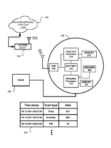
thermostat, and 24 VAC HVAC equipment relay were all connected in a loop with
each
device having only two external connections required.
[0005] When electronics began to be used in thermostats the fact that the
thermostat was
not directly wired to both sides of the transformer for its power source
created a problem.
This meant either the thermostat had to have its own independent power source,
such as a
battery, or be hardwired directly from the system transformer. Direct
hardwiring a
"common" wire from the transformer to the electronic thermostat may be very
difficult and
costly. However, there are also disadvantages to using a battery for providing
the operating
power. One primary disadvantage is the need to continually check and replace
the battery. If
the battery is not properly replaced and cannot provide adequate power, the
electronic
thermostat may fail during a period of extreme environmental conditions.
100061 Because many households do not have a direct wire from the system
transformer
(such as a "common" wire), some thermostats have been designed to derive power
from the
transformer through the equipment load. The methods for powering an electronic
thermostat
from the transformer with a single direct wire connection to the transformer
are called "power
stealing" or "power sharing." The thermostat "steals," "shares" or "harvests"
its power
during the "OFF" periods of the heating or cooling system by allowing a small
amount of
current to flow through it into the load coil below its response threshold
(even at maximum
transformer output voltage). During the "ON" periods of the heating or cooling
system the
thermostat draws power by allowing a small voltage drop across itself.
Ideally, the voltage
drop will not cause the load coil to dropout below its response threshold
(even at minimum
transformer output voltage). Examples of thermostats with power stealing
capability include
the Honeywell T8600, Honeywell T8400C, and the Emerson Model 1F97-0671.
However,
these systems do not have power storage means and therefore must always rely
on power
stealing or must use disposable batteries.
2
CA 02853081 2014-04-22
WO 2013/059684
PCT/US2012/061148
[0007] Additionally, microprocessor controlled "intelligent" thermostats may
have more
advanced environmental control capabilities that can save energy while also
keeping
occupants comfortable. To do this, these thermostats require more information
from the
occupants as well as the environments where the thermostats are located. These
thermostats
may also be capable of connection to computer networks, including both local
area networks
(or other "private" networks) and wide area networks such as the Internet (or
other "public"
networks), in order to obtain current and forecasted outside weather data,
cooperate in so-
called demand-response programs (e.g., automatic conformance with power alerts
that may
be issued by utility companies during periods of extreme weather), enable
users to have
remote access and/or control thereof through their network-connected device
(e.g.,
smartphone, tablet computer, PC-based web browser), and other advanced
functionalities that
may require network connectivity.
[0008] Issues arise in relation to providing microprocessor-controlled,
network-connected
thermostats, one or more such issues being at least partially resolved by one
or more of the
embodiments described hereinbelow. On the one hand, it is desirable to provide
a thermostat
having advanced functionalities such as those associated with relatively
powerful
microprocessors and reliable wireless communications chips, while also
providing a
thermostat that has an attractive, visually pleasing electronic display that
users will find
appealing to behold and interact with. On the other hand, it is desirable to
provide a
thermostat that is compatible and adaptable for installation in a wide variety
of homes,
including a substantial percentage of homes that are not equipped with the
"common" wire
discussed above. It is still further desirable to provide such a thermostat
that accommodates
easy do-it-yourself installation such that the expense and inconvenience of
arranging for an
HVAC technician to visit the premises to install the thermostat can be avoided
for a large
number of users. It is still further desirable to provide a thermostat having
such processing
power, wireless communications capabilities, visually pleasing display
qualities, and other
advanced functionalities, while also being a thermostat that, in addition to
not requiring a
"common" wire, likewise does not require to be plugged into household line
current or a so-
called "power brick," which can be inconvenient for the particular location of
the thermostat
as well as unsightly.
3
BRIEF SUMMARY OF THE INVENTION
100091 This patent specification relates to systems and methods for the
monitoring and control
of energy-consuming systems or other resource-consuming systems. More
particularly, this
patent specification relates control units that govern the operation of energy-
consuming
systems, household devices, or other resource-consuming systems, including
methods for
providing electrical power for thermostats that govern the operation of
heating, ventilation, and
air conditioning (HVAC) systems. In a preferred embodiment, the
thermostat includes selected feature combinations that have been found to be
advantageous for
the facilitation of do-it-yourself thermostat installation, the accommodation
of a variety of
different practical installation scenarios (including scenarios where a "C"
power wire is not
available), the provisioning of relatively power-intensive advanced interfaces
and functionalities
(e.g., a large visually pleasing electronic display, a relatively powerful
general purpose
microprocessor, and a reliable Wi-Fi communications chip) even where a "C"
power wire is not
available, the facilitation of operational robustness and durability, compact
device size,
quietness of operation, and other advantageous characteristics described in
the instant disclosure
and/or the commonly assigned applications referenced herein.
100101 According to some embodiments of the present invention, a thermostat
includes a
plurality of HVAC (heating, ventilation, and air conditioning) wire connectors
configured to
receive a plurality of HVAC control wires corresponding to an HVAC system. The
thermostat also includes a thermostat processing and control circuit
configured to at least
partially control the operation of the HVAC system and a powering circuit
coupled to the
HVAC wire connectors and configured to provide an electrical load power to the
thermostat
processing and control circuit. The powering circuit has a power extraction
circuit configured
to extract electrical power from one or more of the plurality of received HVAC
control wires
up to a first level of electrical power, a rechargeable battery, and a power
control circuit
coupled to the power extraction circuit, the rechargeable battery, and the
thermostat
processing and control circuit. The power control circuit is configured such
that:
(i) during a first time period in which the electrical load power
required
by the thermostat processing and control circuit is less than said first level
of
electrical power, the power control circuit supplies the required electrical
load
4
CA 2853081 2019-05-14
CA 02853081 2014-04-22
WO 2013/059684
PCT/US2012/061148
power to the thermostat processing and control circuit and charges the
rechargeable battery, if needed, using power from the power extraction
circuit;
and
(ii) during a second time period in which the electrical load power
required
by the thermostat processing and control circuit is greater than said first
level
of electrical power, the power control circuit discharges the rechargeable
battery and supplies the required electrical load power to the thermostat
processing and control circuit using a combination of (a) power from the
power extraction circuit, and (b) power from the discharging rechargeable
battery.
[0011] In some embodiments of the above thermostat, the first level of power
is determined
according to a selection of HVAC control wire from which the power extraction
circuit is
extracting electrical power. In some embodiment, the selected HVAC control
wire is either a
call relay wire or a common wire, wherein the first level of power associated
with the
common wire is higher than the first level of power associated with a call
relay wire. In some
embodiments, the HVAC control wire from which power is extracted is
automatically
selected based on an automatic identification of the HVAC control wires that
are inserted into
the thermostat.
[0012] In other embodiments of the above thermostat, the thermostat includes a
main
processor and a display, each having a low-power usage state and a high-power
usage state,
wherein the processor and display are selectively operated such that a long-
term average
power used by the thermostat circuitry is less than said first level of
electrical power. In
some embodiment, the thermostat further includes a backplate processor
configured to
operate in a low-power state, the backplate processor also configured to poll
sensors in the
system on an ongoing basis, while allowing the main processor to operate in
the low-power
usage state. In some embodiments, the backplate processor is configured to
cause the main
processor to move from the low-power usage state to the high-power usage
state.
[0013] According to an alternative embodiment of the present invention, a
method for
controlling an HVAC (heating, ventilation, and air conditioning) system
includes connecting
one or more HVAC control wires to corresponding HVAC wire connectors in a
thermostat,
CA 02853081 2014-04-22
WO 2013/059684
PCT/US2012/061148
which includes a rechargeable battery and is configured to at least partially
control the
operation of the HVAC system. The method also includes extracting electrical
power from
the one or more received HVAC control wires up to a first level of electrical
power. During a
first time period in which the electrical load power required by the
thermostat is less than said
first level of electrical power, the required electrical load power is
supplied to the thermostat
and the rechargeable battery is charged, if needed, using the extracted power.
During a
second time period in which the electrical load power required by the
thermostat is greater
than said first level of electrical power, the rechargeable battery is
discharged and the
required electrical load power is supplied to the thermostat using a
combination of the
extracted power and power from the discharging rechargeable battery.
[0014] According to another embodiment, a thermostat includes a plurality of
HVAC
(heating, ventilation, and air conditioning) wire connectors configured to
receive a plurality
of HVAC control wires corresponding to an HVAC system, and a thermostat
processing and
control circuit configured to at least partially control the operation of the
HVAC system. The
thermostat also has a powering circuit coupled to the HVAC wire connectors and
configured
to provide an electrical load power to the thermostat processing and control
circuit using
electrical power extracted from one or more of the plurality of received HVAC
control wires
and electrical power from a rechargeable battery.
[0015] A further understanding of the nature and advantages of the present
invention may
be realized by reference to the remaining portions of the specification and
the drawings.
BRIEF DESCRIPTION OF THE DRAWINGS
[0016] FIG. 1 is a diagram of an enclosure with an HVAC system, according to
some
embodiments;
[0017] FIG. 2 is a diagram of an HVAC system, according to some embodiments;
[0018] FIG. 3A is a schematic block diagram that provides an overview of some
components inside a thermostat in accordance with embodiments of the present
invention;
[0019] FIG. 3B is a block diagram of some circuitry of a thermostat, according
to some
embodiments;
6
CA 02853081 2014-04-22
WO 2013/059684
PCT/US2012/061148
[0020] FIGS. 4A-4C schematically illustrate the use of auto-switching
connectors being
used to automatically select a source for power harvesting, according to some
embodiments;
[0021] FIG. 5 is a schematic of a half-bridge sense circuit, according to some
embodiments;
[0022] FIGS. 6A-6B are schematics showing the high voltage buck, bootstrap LDO
and
battery LDO power circuitry, according to some embodiments;
[0023] FIG. 6C shows a battery charging circuit and rechargeable battery,
according to
some embodiments;
[0024] FIG. 7 illustrates an exploded perspective view of a versatile sensing
and control
unit (VSCU unit) and an HVAC-coupling wall dock according to an embodiment;
[0025] FIGS. 8A-8B illustrates conceptual diagrams of HVAC-coupling wall
docks,
according to some embodiments;
[0026] FIGS. 9A-9B illustrate a thermostat having a user-friendly interface,
according to
some embodiments;
[0027] FIGS. 9C illustrates a cross-sectional view of a shell portion of a
frame of the
thermostat of FIGS. 9A-9B;
[0028] FIGS. 10A-10B illustrate exploded front and rear perspective views,
respectively, of
a thermostat with respect to its two main components, which are the head unit
and the back
plate;
[0029] FIGS. 11A-11B illustrate exploded front and rear perspective views,
respectively, of
the head unit with respect to its primary components;
[0030] FIGS. 12A-12B illustrate exploded front and rear perspective views,
respectively, of
the head unit frontal assembly with respect to its primary components;
[0031] FIGS. 13A-13B illustrate exploded front and rear perspective views,
respectively, of
the backplate unit with respect to its primary components;
[0032] FIG 14 illustrates a perspective view of a partially assembled head
unit front,
according to some embodiments;
7
CA 02853081 2014-04-22
WO 2013/059684
PCT/US2012/061148
[0033] FIG. 15 illustrates a head-on view of the head unit circuit board,
according to one
embodiment;
[0034] FIG. 16 illustrates a rear view of the backplate circuit board,
according to one
embodiment;
[0035] FIGS. 17A-17C illustrate conceptual examples of the sleep-wake timing
dynamic, at
progressively larger time scales; according to one embodiment;
[0036] FIG. 18 illustrates a self-descriptive overview of the functional
software, firmware,
and/or programming architecture of the head unit microprocessor, according to
one
embodiment;
[0037] FIG. 19 illustrates a self-descriptive overview of the functional
software, firmware,
and/or programming architecture of the backplate microcontroller, according to
one
embodiment; and
[0038] FIG. 20 illustrates a thermostat 2000 according to a preferred
embodiment.
DETAILED DESCRIPTION OF THE INVENTION
[0039] In the following detailed description, for purposes of explanation,
numerous specific
details are set forth to provide a thorough understanding of the various
embodiments of the
present invention. Those of ordinary skill in the art will realize that these
various
embodiments of the present invention are illustrative only and are not
intended to be limiting
in any way. Other embodiments of the present invention will readily suggest
themselves to
such skilled persons having the benefit of this disclosure.
[0040] In addition, for clarity purposes, not all of the routine features of
the embodiments
described herein are shown or described. One of ordinary skill in the art
would readily
appreciate that in the development of any such actual embodiment, numerous
embodiment-
specific decisions may be required to achieve specific design objectives.
These design
objectives will vary from one embodiment to another and from one developer to
another.
Moreover, it will be appreciated that such a development effort might be
complex and time-
consuming but would nevertheless be a routine engineering undertaking for
those of ordinary
skill in the art having the benefit of this disclosure.
8
CA 02853081 2014-04-22
WO 2013/059684
PCT/US2012/061148
[0041] It is to be appreciated that while one or more embodiments are
described further
herein in the context of typical HVAC system used in a residential home, such
as single-
family residential home, the scope of the present teachings is not so limited.
More generally,
thermostats according to one or more of the prefen-ed embodiments are
applicable for a wide
variety of enclosures having one or more HVAC systems including, without
limitation,
duplexes, townhomes, multi-unit apartment buildings, hotels, retail stores,
office buildings
and industrial buildings. Further, it is to be appreciated that while the
terms user, customer,
installer, homeowner, occupant, guest, tenant, landlord, repair person, and
the like may be
used to refer to the person or persons who are interacting with the thermostat
or other device
or user interface in the context of one or more scenarios described herein,
these references are
by no means to be considered as limiting the scope of the present teachings
with respect to
the person or persons who are performing such actions.
[0042] Provided according to one or more embodiments are systems, methods,
computer
program products, and related business methods for controlling one or more
HVAC systems
based on one or more versatile sensing and control units (VSCU units), each
VSCU unit
being configured and adapted to provide sophisticated, customized, energy-
saving HVAC
control functionality while at the same time being visually appealing, non-
intimidating,
elegant to behold, and delightfully easy to use. The term "thermostat" is used
hereinbelow to
represent a particular type of VSCU unit (Versatile Sensing and Control) that
is particularly
applicable for HVAC control in an enclosure. Although "thermostat" and "VSCU
unit" may
be seen as generally interchangeable for the contexts of HVAC control of an
enclosure, it is
within the scope of the present teachings for each of the embodiments
hereinabove and
hereinbelow to be applied to VSCU units having control functionality over
measurable
characteristics other than temperature (e.g., pressure, flow rate, height,
position, velocity,
acceleration, capacity, power, loudness, brightness) for any of a variety of
different control
systems involving the governance of one or more measurable characteristics of
one or more
physical systems, and/or the governance of other energy or resource consuming
systems such
as water usage systems, air usage systems, systems involving the usage of
other natural
resources, and systems involving the usage of various other forms of energy.
[0043] FIG. 1 is a diagram illustrating an exemplary enclosure using a
thermostat 110
implemented in accordance with the present invention for controlling one or
more
9
CA 02853081 2014-04-22
WO 2013/059684
PCT/US2012/061148
environmental conditions. For example, enclosure 100 illustrates a single-
family dwelling
type of enclosure using a learning thermostat 110 (also referred to for
convenience as
"thermostat 110") for the control of heating and cooling provided by an HVAC
system 120.
Alternate embodiments of the present invention may be used with other types of
enclosures
including a duplex, an apartment within an apartment building, a light
commercial structure
such as an office or retail store, or a structure or enclosure that is a
combination of these and
other types of enclosures.
[0044] Some embodiments of thermostat 110 in FIG. 1 incorporate one or more
sensors to
gather data from the environment associated with enclosure 100. Sensors
incorporated in
thermostat 110 may detect occupancy, temperature, light and other
environmental conditions
and influence the control and operation of HVAC system 120. Sensors
incorporated within
thermostat 110 do not protrude from the surface of the thermostat 110 thereby
providing a
sleek and elegant design that does not draw attention from the occupants in a
house or other
enclosure. As a result, thermostat 110 and readily fits with almost any decor
while adding to
the overall appeal of the interior design.
[0045] As used herein, a "learning" thermostat refers to a thermostat, or one
of plural
communicating thermostats in a multi-thermostat network, having an ability to
automatically
establish and/or modify at least one future setpoint in a heating and/or
cooling schedule based
on at least one automatically sensed event and/or at least one past or current
user input.
[0046] As used herein, a "primary" thermostat refers to a thermostat that is
electrically
connected to actuate all or part of an HVAC system, such as by virtue of
electrical connection
to HVAC control wires (e.g. W, G, Y, etc.) leading to the HVAC system.
[0047] As used herein, an "auxiliary" thermostat refers to a thermostat that
is not
electrically connected to actuate an HVAC system, but that otherwise contains
at least one
sensor and influences or facilitates primary thermostat control of an HVAC
system by virtue
of data communications with the primary thermostat.
[0048] In one particularly useful scenario, the thermostat 110 is a primary
learning
thermostat and is wall-mounted and connected to all of the HVAC control wires,
while the
remote thermostat 112 is an auxiliary learning thermostat positioned on a
nightstand or
CA 02853081 2014-04-22
WO 2013/059684
PCT/US2012/061148
dresser, the auxiliary learning thermostat being similar in appearance and
user-interface
features as the primary learning thermostat, the auxiliary learning thermostat
further having
similar sensing capabilities (e.g., temperature, humidity, motion, ambient
light, proximity) as
the primary learning thermostat, but the auxiliary learning thermostat not
being connected to
any of the HVAC wires. Although it is not connected to any HVAC wires, the
auxiliary
learning thermostat wirelessly communicates with and cooperates with the
primary learning
thermostat for improved control of the HVAC system, such as by providing
additional
temperature data at its respective location in the enclosure, providing
additional occupancy
information, providing an additional user interface for the user, and so
forth.
[0049] It is to be appreciated that while certain embodiments are particularly
advantageous
where the thermostat 110 is a primary learning thermostat and the remote
thermostat 112 is
an auxiliary learning thermostat, the scope of the present teachings is not so
limited. Thus,
for example, while certain initial provisioning methods that automatically
pair associate a
network-connected thermostat with an online user account are particularly
advantageous
where the thermostat is a primary learning thermostat, the methods are more
generally
applicable to scenarios involving primary non-learning thermostats, auxiliary
learning
thermostats, auxiliary non-learning thermostats, or other types of network-
connected
thermostats and/or network-connected sensors. By way of further example, while
certain
graphical user interfaces for remote control of a thermostat may be
particularly advantageous
where the thermostat is a primary learning thermostat, the methods are more
generally
applicable to scenarios involving primary non-learning thermostats, auxiliary
learning
thermostats, auxiliary non-learning thermostats, or other types of network-
connected
thermostats and/or network-connected sensors. By way of even further example,
while
certain methods for cooperative, battery-conserving information polling of a
thermostat by a
remote cloud-based management server may be particularly advantageous where
the
thermostat is a primary learning thermostat, the methods are more generally
applicable to
scenarios involving primary non-learning thermostats, auxiliary learning
thermostats,
auxiliary non-learning thermostats, or other types of network-connected
thermostats and/or
network-connected sensors.
[0050] Enclosure 100 further includes a private network accessible both
wirelessly and
through wired connections and may also be referred to as a Local Area Network
or LAN.
11
CA 02853081 2014-04-22
WO 2013/059684
PCT/US2012/061148
Network devices on the private network include a computer 124, thermostat 110
and remote
thermostat 112 in accordance with some embodiments of the present invention.
In one
embodiment, the private network is implemented using an integrated router 122
that provides
routing, wireless access point functionality, firewall and multiple wired
connection ports for
connecting to various wired network devices, such as computer 124. Each device
is assigned
a private network address from the integrated router 122 either dynamically
through a service
like Dynamic Host Configuration Protocol (DHCP) or statically through actions
of a network
administrator. These private network addresses may be used to allow the
devices to
communicate with each directly over the LAN. Other embodiments may instead use
multiple
discrete switches, routers and other devices (not shown) to perform more other
networking
functions in addition to functions as provided by integrated router 122.
[0051] Integrated router 122 further provides network devices access to a
public network,
such as the Internet, provided enclosure 100 has a connection to the public
network generally
through a cable-modem, DSL modem and an Internet service provider or provider
of other
public network service. Public networks like the Internet are sometimes
referred to as a
Wide-Area Network or WAN. In the case of the Internet, a public address is
assigned to a
specific device allowing the device to be addressed directly by other devices
on the Internet.
Because these public addresses on the Internet are in limited supply, devices
and computers
on the private network often use a router device, like integrated router 122,
to share a single
public address through entries in Network Address Translation (NAT) table. The
router
makes an entry in the NAT table for each communication channel opened between
a device
on the private network and a device, server, or service on the Internet. A
packet sent from a
device on the private network initially has a "source" address containing the
private network
address of the sending device and a "destination" address corresponding to the
public network
address of the server or service on the Internet. As packets pass from within
the private
network through the router, the router replaces the "source" address with the
public network
address of the router and a "source port" that references the entry in the NAT
table. The
server on the Internet receiving the packet uses the "source" address and
"source port" to send
packets back to the router on the private network which in turn forwards the
packets to the
proper device on the private network doing a corresponding lookup on an entry
in the NAT
table.
12
CA 02853081 2014-04-22
WO 2013/059684
PCT/US2012/061148
[0052] Entries in the NAT table allow both the computer device 124 and the
thermostat 110
to establish individual communication channels with a thermostat management
system (not
shown) located on a public network such as the Internet. In accordance with
some
embodiments, a thermostat management account on the thermostat management
system
enables a computer device 124 in enclosure 100 to remotely access thermostat
110. The
thermostat management system passes information from the computer device 124
over the
Internet and back to thermostat 110 provided the thermostat management account
is
associated with or paired with thermostat 110. Accordingly, data collected by
thermostat 110
also passes from the private network associated with enclosure 100 through
integrated router
122 and to the thermostat management system over the public network. Other
computer
devices not in enclosure 100 such as Smartphones, laptops and tablet computers
(not shown
in FIG. 1) may also control thermostat 110 provided they have access to the
public network
where the thermostat management system and thermostat management account may
be
accessed. Further details on accessing the public network, such as the
Internet, and remotely
accessing a thermostat like thermostat 110 in accordance with embodiments of
the present
invention is described in further detail later herein.
[0053] In some embodiments, thermostat 110 may wirelessly communicate with
remote
thermostat 112 over the private network or through an ad hoc network formed
directly with
remote thermostat 112. During communication with remote thermostat 112,
thermostat 110
may gather information remotely from the user and from the environment
detectable by the
remote thermostat 112. For example, remote thermostat 112 may wirelessly
communicate
with the thermostat 110 providing user input from the remote location of
remote thermostat
112 or may be used to display information to a user, or both. Like thermostat
110,
embodiments of remote thermostat 112 may also include sensors to gather data
related to
occupancy, temperature, light and other environmental conditions. In an
alternate
embodiment, remote thermostat 112 may also be located outside of the enclosure
100.
[0054] FIG. 2 is a schematic diagram of an HVAC system controlled using a
thermostat
designed in accordance with embodiments of the present invention. HVAC system
120
provides heating, cooling, ventilation, and/or air handling for an enclosure
100, such as a
single-family home depicted in FIG. 1. System 120 depicts a forced air type
heating and
13
CA 02853081 2014-04-22
WO 2013/059684
PCT/US2012/061148
cooling system, although according to other embodiments, other types of HVAC
systems
could be used such as radiant heat based systems, heat-pump based systems, and
others.
[0055] In heating, heating coils or elements 242 within air handler 240
provide a source of
heat using electricity or gas via line 236. Cool air is drawn from the
enclosure via return air
duct 246 through filter 270, using fan 238 and is heated through heating coils
or elements
242. The heated air flows back into the enclosure at one or more locations via
supply air duct
system 252 and supply air registers such as register 250. In cooling, an
outside compressor
230 passes a gas such as Freon through a set of heat exchanger coils 244 to
cool the gas. The
gas then goes through line 232 to the cooling coils 234 in the air handler 240
where it
expands, cools and cools the air being circulated via fan 238. A humidifier
254 may
optionally be included in various embodiments that returns moisture to the air
before it passes
through duct system 252. Although not shown in FIG. 2, alternate embodiments
of HVAC
system 120 may have other functionality such as venting air to and from the
outside, one or
more dampers to control airflow within the duct system 252 and an emergency
heating unit.
Overall operation of HVAC system 120 is selectively actuated by control
electronics 212
communicating with thermostat 110 over control wires 248.
[0056] Referring to FIG. 3A, a schematic block diagram provides an overview of
some
components inside a thermostat in accordance with embodiments of the present
invention.
Thermostat 308 is similar to thermostat 112 in FIG. 1 except that thermostat
308 also
illustrates and highlights selected internal components including a Wi-Fi
module 312 and
antenna, a head unit processor 314 with associated memory 315, a backplate
processor 316
with associated memory, and sensors 322 (e.g., temperature, humidity, motion,
ambient light,
proximity). In one embodiment, head unit processor 314 can be a Texas
Instruments AM3703
Sitara ARM microprocessor while backplate processor 316, which may be more
specifically
referenced to as a "microcontroller", can be a Texas Instruments MSP430F
microcontroller.
Further details regarding the physical placement and configuration of the
thermostat head
unit, backplate, and other physical elements are described in the commonly
assigned U.S.
Ser. No. 13/199,108, supra.
[0057] For some embodiments, the backplate processor 316 is a very low-power
device
that, while having some computational capabilities, is substantially less
powerful than the
14
CA 02853081 2014-04-22
WO 2013/059684
PCT/US2012/061148
head unit processor 314. The backplate processor 316 is coupled to, and
responsible for
polling on a regular basis, most or all of the sensors 322 including the
temperature and
humidity sensors, motion sensors, ambient light sensors, and proximity
sensors. For sensors
322 that may not be located on the backplate hardware itself but rather are
located in the head
unit, ribbon cables or other electrical connections between the head unit and
backplate are
provided for this purpose. Notably, there may be other sensors (not shown) for
which the
head unit processor 314 is responsible, with one example being a ring rotation
sensor that
senses the user rotation of an outer ring of the thermostat. Each of the head
unit processor
314 and backplate processor 316 is capable of entering into a "sleep" state,
and then "waking
up" to perform various tasks.
[0058] The backplate processor 316, which in some embodiments will have a low-
power
sleep state that corresponds simply to a lower clock speed, generally enters
into and out of its
sleep mode substantially more often than does the more powerful head unit
processor 314.
The backplate processor 316 is capable of waking up the head unit processor
314 from its
sleep state. For one preferred embodiment directed to optimal battery
conservation, the head
unit processor 314 is allowed to sleep when its operations are not being
called for, while the
backplate processor 316 performs polling of the sensors 322 on an ongoing
basis, maintaining
the sensor results in memory 317. The backplate processor 316 will wake up the
head unit
processor 314 in the event that (i) the sensor data indicates that an HVAC
operation may be
called for, such as if the current temperature goes below a currently active
heating setpoint, or
(ii) the memory 317 gets full and the sensor data needs to be transferred up
to the head unit
processor 314 for storage in the memory 315. The sensor data can then be
pushed up to the
cloud server (thermostat management server) during a subsequent active
communication
session between the cloud server and the head unit processor 314.
[0059] In the case of Wi-Fi module 312, one embodiment may be implemented
using
Murata Wireless Solutions LBWA19XSLZ module, which is based on the Texas
Instruments
WL1270 chipset supporting the 802.11 big/1n WLAN standard. Embodiments of the
present
invention configure and program Wi-Fi module 312 to allow thermostat 308 to
enter into a
low power or "sleep" mode to conserve energy until one or several events
occurs. For
example, in some embodiments the Wi-Fi module 312 may leave this low power
mode when
CA 02853081 2014-04-22
WO 2013/059684
PCT/US2012/061148
a user physically operates thermostat 308, which in turn may also cause
activation of both
head-unit processor 314 and backplate processor 316 for controlling functions
in head-unit
and backplate portions of thermostat 110.
[0060] It is also possible for Wi-Fi module 312 to wake from a low power mode
at regular
intervals in response to a beacon from wireless access point 372. To conserve
energy, Wi-Fi
module 312 may briefly leave the low power mode to acknowledge the beacon as
dictated by
the appropriate wireless standard and then return to a low power mode without
activating the
processors or other components of thermostat 308 in FIG. 3A. In an alternative
embodiment,
Wi-Fi module 312 may also respond to the beacon by awaking briefly and then
activating
backplate processor 316, head unit processor 314, or other portions of
thermostat 308 to
gather data through sensors 322 and store the results in a data log 326 with a
time stamp,
event type and corresponding data listed for future reference. in accordance
with one
embodiment, backplate processor 316 may collect data in data log 326 and store
in memory
320 for a period of time or until the log reaches a maximum predetermined
size. At that point,
the backplate processor 316 may wake head unit processor 314 to coordinate an
upload of the
data log 326 stored in memory 320 over a public network, such as the Internet,
to cloud-based
management server 516 . Uploading data log 326 less frequently saves time and
energy
associated with more frequent transmission of individual records or log
entries.
[0061] In yet another embodiment, Wi-Fi module 312 may selectively filter an
incoming
data packet to determine if the header is merely an acknowledgement packet
(i.e., a keep-
alive packet) or contains a payload that needs further processing. If the
packet contains only a
header and no payload, the Wi-Fi module 312 may be configured to either ignore
the packet
or send a return acknowledgement to the thermostat management system or other
source of
the packet received.
[0062] In further embodiments, Wi-Fi module 312 may be used to establish
multiple
communication channels between thermostat 112 and a cloud-based management
server as
will be described and illustrated later in this disclosure. As previously
described, thermostat
112 uses multiple communication channels to receive different types of data
classified with
different levels of priority. In one embodiment, Wi-Fi module 312 may be
programmed to
use one or more filters and a wake-on-LAN feature to then selectively ignore
or discard data
16
CA 02853081 2014-04-22
WO 2013/059684
PCT/US2012/061148
arriving over one or more of these communication channels. For example, low-
priority data
arriving over a port on Wi-Fi module 312 may be discarded by disabling the
corresponding
wake-on-LAN feature associated with the port. This allows the communication
channel to
continue to operate yet conserves battery power by discarding or ignoring the
low-priority
packets.
[0063] Operation of the microprocessors 314, 316, Wi-Fi module 312, and other
electronics
may be powered by a rechargeable battery (not shown) located within the
thermostat 110. In
some embodiments, the battery is recharged directly using 24 VAC power off a
"C" wire
drawn from the HVAC system or an AC-DC transformer coupled directly into the
thermostat
110. Alternatively, one or more different types of energy harvesting may also
be used to
recharge the internal battery if these direct methods are not available, such
as one or more of
the methods described herein. Embodiments of the present invention communicate
and
operate the thermostat 110 in a manner that promotes efficient use of the
battery while also
keeping the thermostat operating at a high level of performance and
responsiveness
controlling the HVAC system. Some embodiments may use the battery-level charge
and the
priority or relative importance of a communication to determine when a
thermostat
management system located on a public network such as the Internet may
communicate with
the thermostat 110. Further details on the communication methods and system
used in
accordance with these embodiments are described in detail later herein.
[0064] Turning now to power harvesting methods and systems, FIG. 3B is a block
diagram
of some circuitry of a thermostat, according to some embodiments. Circuitry
300, according
to some embodiments, is a backplate of a thermostat. A number of HVAC wires
can be
attached using HVAC terminals 372. One example of which is the WI terminal
374. Each
terminal is used to control an HVAC function. According to some embodiments,
each of the
wires from the terminals Wl, W2, Yl, Y2, G, 0/B, AUX and E is connected to
separate
isolated FET drives 370. The common HVAC functions for each of the terminals
are: WI
and W2 heating; Y1 and Y2 for cooling; G for fan; 0/B for heatpumps; and E for
emergency
heat. Note that although the circuitry 300 is able control 8 functions using
the isolated FET
drives 370, according to some embodiments, other functions, or fewer functions
can be
controlled. For example circuitry for a more simply equipped HVAC system may
only have
a single heating (W), and single cooling (Y) and a fan (G), in which case
there would only be
17
three isolated FET drives 370. According to a preferred embodiment, 5 FET
drives 370 are
provided, namely heating (W), cooling (Y), fan (G), auxiliary (AUX) and
compressor direction
(0/B). Not shown are the circuit returns such as RH (return for heat) and RC
(return for
cooling). According to some embodiments the thermostat can control a
humidifier and/or de-
humidifier. Further details relating to isolated FET drives 370 are described
in co-pending U.S.
Patent Application Ser. No. 13/034,674, entitled "Thermostat Circuitry for
Connection to
HVAC Systems," supra.
[00651 The HVAC functions are controlled by the HVAC control general purpose
input/outputs (GPI0s) 322 within microcontroller (MCU) 320. MCU 320 is a
general
purpose microcontroller such as the MSP430 16-bit ultra-low power MCU
available from
Texas Instruments. MCU 320 communicates with the head unit via Head Unit
Interface 340.
The head unit together with the backplate make up the thermostat. The head
unit has user
interface capability such that it can display information to a user via an LCD
display and
receive input from a user via buttons and/or touch screen input devices.
According to some
embodiments, the head unit has network capabilities for communication to other
devices
either locally or over the internet. Through such network capability, for
example, the
thermostat can send information and receive commands and setting from a
computer located
elsewhere inside or outside of the enclosure. The MCU detects whether the head
unit is
attached to the backplate via head unit detect 338.
[00661 Clock 342 provides a low frequency clock signal to MCU 320, for example
32.768kHz. According to some embodiments there are two crystal oscillators,
one for high
frequency such as 16M1-Iz and one for the lower frequency. Power for MCU 320
is supplied
at power input 344 at 3.0 V. Circuitry 336 provides wiring detection, battery
measurement,
and buck input measurement. A temperature sensor 330 is provided, and
according to some
embodiments and a humidity sensor 332 are provided. According to some
embodiments, one
or more other sensors 334 are provided such as: pressure, proximity (e.g.
using infrared),
ambient light, and pyroelectric infrared (PIR).
100671 Power circuitry 350 is provided to supply power. According to some
embodiments,
when the thermostat is first turned on with insufficient battery power, a
bootstrap power system
is provided. A high voltage low dropout voltage regulator (LDO) 380 provides
3.0
18
CA 2853081 2019-05-14
volts of power for the bootstrap of the MCU 320. The bootstrap function can be
disabled under
MCU control but according to some embodiments the bootstrap function is left
enabled to
provide a ''safety net" if the head unit supply vanishes for any reason. For
example, if the head-
unit includes the re-chargeable battery 384 and is removed unexpectedly, the
power would be
lost and the bootstrap function would operate. The input to this Bootstrap LDO
380 is provided
by connectors and circuitry 368 that automatically selects power from common
362 (highest
priority), cool 366 (lower priority); or heat (lowest priority) 364.
[0068] In normal operation, a 3.0 volt primary LDO 382 powers the backplate
circuitry and
itself is powered by VCC Main. According to some embodiments, high voltage
buck 360 is
provided as a second supply in the backplate. The input to this supply is the
circuitry 368.
According to some embodiments, the high voltage buck 380 can supply a maximum
of 100mA
at 4.5v. According to some embodiments, the VCC main and the Primary LDO 382
can be
powered by a rechargeable battery (shown in FIG. 7) in cases where there is no
alternative
power source (such as the high voltage buck or USB power, for example).
[0069] FIGS. 4A-C schematically illustrate the use of auto-switching
connectors being used
to automatically select a source for power harvesting, according to some
embodiments. The
connectors 362, 364, and 366 are connectors as shown in FIG. 3B. For further
details
regarding preferred automatically switching connectors, see co-pending U.S.
Patent
Application Ser. No. 13/034,666, entitled "Thermostat Wiring Connector" filed
on even date
herewith. The connector 362 is used for connection to an HVAC "C" (common)
wire and
includes two switched pairs of normally closed secondary conductors 410 and
412. The
connector 366 is used for connection to an HVAC "Y" (cooling) wire and
includes one
switched pair of normally closed secondary conductors 454. The connector 364
is used for
connection to an HVAC "W" (heating) wire. Note that although not shown in
FIGS. 4A-C,
one or more additional pairs of switched secondary conductors can be provided
with any of
the connectors 362, 366 and 365, such as could be used for the purpose of
electronically
detecting the presence of an HVAC system wire to the connector. Power
harvesting circuitry
460 is used to supply power to the thermostat and is also connected to the Re
wire 462 (or
according to other embodiment the Rh wire). For example, the power harvesting
circuitry
460 can include the HV buck 360 and Bootstrap LDO 380 as shown in and
described with
respect to FIGS. 3 and 6A-B.
19
CA 2853081 2019-05-14
CA 02853081 2014-04-22
WO 2013/059684
PCT/US2012/061148
[0070] FIG. 4A shows the case of the switches 454, 410 and 412 when no C wire
and no Y
wire is attached. In this case all of the switches 454, 410 and 412 are closed
and the power
harvesting circuitry 460 is connected at input 464 with the W wire via circuit
paths 420, 422
and 426. FIG. 4B shows the case of the switches 454, 410 and 412 when no C
wire is
attached but there is a Y wire attached. In this case switches 410 and 412 are
closed but
switch 454 is opened due to the presence of the Y wire. In this case the power
harvesting
circuitry 460 is connected at input 464 with the Y wire via circuit paths 424
and 428. FIG.
4C shows the case of the switches 454, 410, and 412, when both C and Y wires
are attached.
In this case all the switches 454, 410 and 412 are open and the power
harvesting circuitry 460
is connected at input 464 with the C wire via circuit path 430. Note that the
case of a
connection of C and W wires and no Y wire is not shown but that in this case
the W wire
would not be connected to circuitry 420 since switch 410 would be open. Thus,
through the
use of circuitry and the connectors shown, the power harvesting circuitry is
automatically
switched so as to use connections to C, Y and W wires in decreasing order of
priority.
Preferably, the C wire is the highest priority as this ordinarily provides the
best power source,
if available. Note that according to some embodiments, the Y and W priorities
are reversed
to make W higher priority than Y.
[0071] FIG. 5 is a schematic of a half-bridge sense circuit, according to some
embodiments. Circuit 500 provides voltage sensing, clipped to 3.0 volts, for
presence
detection and current sensing. At inputs 502, 504 and 506 are the 24VAC
waveforms from
three of the HVAC circuits. In the case shown in FIG. 5, inputs 502, 504 and
506 are for
HVAC WI, HVAC Y1 and HVAC G, respectively. The sense input bias buffer 550 is
provided as shown.Note that a voltage divider is used in each case that takes
the voltage from
24 volts to approximately 4 volts. Clamp diodes 520a, 520b and 520c ensure
that the voltage
goes no higher or lower than the range of the microcontroller 320 (shown in
FIG. 3B). The
Sense outputs 530, 532 and 534 are connected to the microcontroller 320 so
that the
microcontroller 320 can sense the presence of a signal on the HVAC lines. The
circuits are
repeated for the other HVAC lines so that the microcontroller can detect
signals on any of the
HVAC
[0072] FIGS. 6A-B are schematics showing the high voltage buck, bootstrap LDO
and
battery LDO power circuitry, according to some embodiments. FIG. 6A shows the
input 464
from the connector selected power, which corresponds to input 464 to power
circuitry 460 in
FIG. 4. The diodes 632 are used to rectify the AC power signal from the HVAC
power
transformer wire that is selected by the connector circuitry shown in FIG. 4.
When the
thermostat is installed in a building having two HVAC power transformers, such
as may be
the case when an existing HVAC heating-only system is upgraded to add an HVAC
cooling
system. In such cases, there are two power wires from the HVAC system, often
called "Rh"
the power wire directly from the heating system transformer, and "Rc" the
power wire directly
from the cooling transformer. Input 462 is from a terminal connected to the Rc
wire.
According to some embodiments, the Rc and Rh terminals are switched using
automatic
switching or other jumperless design, as shown and described in co-pending
U.S. Patent
Application Ser. No. 13/034,674, entitled "Thermostat Circuitry for Connection
to HVAC
Systems," filed February 24, 2011.
[0073] Rectified input 624 is input to the high voltage buck circuit 610,
according to some
embodiments. In buck circuit 610, which corresponds to high voltage buck 360
in FIG. 3B, the
voltage on the input capacitors 612, 614 and 616 of high voltage buck 610can
be measured by
the MCU 320 (of FIG. 3B) at node 620, allowing the MCU to momentarily open the
WI or Yl
contacts during an "enabled" or "on" phase in order to recharge the buck input
capacitors 612,
614 and 616 and continue power harvesting. According to some embodiments, the
same
HVAC circuit (e.g. heating or cooling) is used for power harvesting, whether
or not there is
more than one HVAC function in the system. According to some other
embodiments, when the
thermostat is used with an HVAC system having two circuits (e.g. heating and
cooling), the
system will harvest power from the non-activated circuit. In cases where a
common wire is
available from the HVAC power transformer, the system preferably does not
power harvest at
all from the heating and cooling circuits. According to some embodiments, the
step down
converter 630 is a high efficiency, high voltage 100mA synchronous step-down
converter such
as the LTC3631 from Linear Technology. According to some embodiments, inductor
642 is a
100uH power inductor such as the M0S6020 from Coilcraft. According to some
embodiments,
one or more other types of elements in addition to or instead of input
capacitors 612, 614 and
616 are used to store electrical energy during power harvesting when the HVAC
function is
active (or "on"). For example, magnetic elements such as inductors and/or
transformers can be
used.
21
CA 2853081 2019-05-14
CA 02853081 2014-04-22
WO 2013/059684
PCT/US2012/061148
[0074] In order to control the HVAC functions, the HVAC function wire is
shorted to the
return or power wire. For example, in the case of heating, the W wire is
shorted to the Rh
(or R or Re depending on the configuration). In the case of cooling the Y wire
is shorted to
the Re (or R or Rh depending on the configuration). By shorting these two
wires, the 24
VAC transformer is placed in series with a relay that controls the HVAC
function. However,
for power harvesting, a problem is that when these wires are shorted, there is
no voltage
across them, and when open, there is no current flow. Since power equals
voltage multiplied
by current, if either quantity is zero the power that can be extracted is
zero. According to
some embodiments, the power harvesting circuitry allows power to be taken from
the two
wires in both the states of HVAC ¨ the HVAC "on" and the HVAC "off'.
[0075] In the HVAC "off "state, some energy can be harvested from these two
wires by
taking less energy than would cause the of the relay to turn on, which would
cause the HVAC
function to erroneously turn on. Based on testing, it has been found that HVAC
functions
generally do not turn on when (0.040A*4.5V) = 0.180 watts is extracted at the
output. So
after the input diodes, capacitors, and switching regulator, this allows us to
take 40 mA at 4.5
volts from these wires without turning on the HVAC system.
[0076] In the HVAC "on" state, the two wires must be connected together to
allow current
to flow, which turns on the HVAC relay. This, however, shorts out the input
supply, so our
system does not get any power when the HVAC "on" switch is closed. To get
around this
problem, the voltage is monitored on the capacitors 612, 614 and 616 at the
input switching
power supply node 620. When the voltage on these capacitors "Cm" drops close
to the point
at which the switching power supply would "Drop out" and lose output
regulation, for
example at about +8 Volts, the HVAC "on" switch is turned off and Cil, is
charged. During
the time that Cin is charging, current is still flowing in the HVAC relay, so
the HVAC relay
stays on. When the Cif, capacitor voltages increases some amount, for example
about +16
Volts, the HVAC "on" switch is closed again, Ch, begins to discharge while it
feeds the
switching regulator, and current continues to flow in the HVAC relay. Note
that Ch, is not
allowed to discharge back to the HVAC "on" switch due to input diodes 632.
When the
voltage on Cif, drops to about +8 Volts the HVAC "on" switch is turned off and
the process
repeats. This continues until the system tells the HVAC "on" switch to go off
because
HVAC is no longer needed. According to some embodiments, the ability of the
HVAC "on"
22
switch to turn on and off relatively quickly is provided by circuitry 450 as
shown in and
described with respect to FIG. 4 of co-pending U.S. Patent Application Ser.
No. 13/034,674,
entitled "Thermostat Circuitry for Connection to HVAC Systems," supra.
100771 According to some embodiments, one or more alternative power harvesting
techniques are used. For example, rather than having the HVAC "on" switch turn
on when
the voltage on C. reaches a certain point, it the system might turn off the
"HVAC "on"
switch for a predetermined period of time instead. According to some
embodiments, power
harvesting is enhanced by synchronizing the power harvesting with the AC
current
waveform.
100781 FIG. 6B is a schematic of high voltage low dropout voltage regulators
used to
provide bootstrap power and battery, according to some embodiments. The
bootstrap LDO
circuitry 680, and battery LDO circuitry correspond to the bootstrap LDO 380
and battery
LDO 382 in FIG. 3 respectively. Rectified input 624 is input to bootstrap
circuit 680.
According to some embodiments, regulator 670 is low-dropout linear regulator
such as the
TPS79801 from Texas Instruments. The output power 690 is provided to the
backplate at
3.0V. The bootstrap disable signal 680 can be used to disable the bootstrap
power unit, as
shown. The input 660 comes from VCC main, which can be, for example, from the
rechargeable battery. According to some embodiments, the low dropout regulator
662 is a
low quiescent current device designed for power-sensitive applications such as
the
TLV70030 from Texas Instruments.
100791 FIG. 6C shows a battery charging circuit 675 and a rechargeable battery
650,
according to some embodiments. The charger 673 is used to charge the lithium-
ion battery
650. In general, li-ion battery capacity depends on what voltage the battery
is charged to, and
the cycle life depends on the charged voltage, how fast the battery is charged
and the
temperature during which the battery is charged. Ordinarily, Li-ion batteries
are charged at
about 4.2V. In some cases the charging voltage is even higher in an attempt to
gain greater
capacity, but at the expense of decreased cycle life. However, in the case of
the rechargeable
battery 650 for use with a wall-mounted thermostat, a greater cycle life is
preferred over
capacity. High capacity is generally not needed since charging power is
available via the
23
CA 2853081 2019-05-14
CA 02853081 2014-04-22
WO 2013/059684
PCT/US2012/061148
power harvesting circuitry, and greater cycle life is preferred since user
replacement may be
difficult or unavailable. Thus, according to some embodiments, a low charging
speed, low
final float voltage and reduced charging temperature range is preferred.
According to some
embodiments, a final float voltage of between 3.9V and 4.1V is used. According
to some
embodiments a final float voltage of less than 4.0V is used, such as 3.95V.
According to
some embodiments, the ratio of charge current to total capacity "C" is also
controlled, such as
charging the battery to 0.2C (0.2 times the rated capacity) to provide better
cycle life than a
higher ratio. According to some embodiments, using a lower charging current
aids in
avoiding unintended tripping of the HVAC relay.
[0080] According to some embodiments, charger 673 is a USB power manager and
li-ion
battery charger such as the LTC4085-3 from Linear Technology. Backplate
voltage 671 is
input to charger 673. The circuitry 672 is used to select the charging
current. In particular
the value of resistor 674 (24.9k) in parallel with resistor 634 (16.9k) in
combination with the
inputs Double Current 638 and High Power 628 are used to select the charging
current. If
High Power 628 and Double Current 638 are both set to 0, then the charging
current is
8.0mA; if the High Power 628 is set to 0 and Double Current 638 is set to 1,
then the
charging current is 19.9mA; if the High Power 628 is set to 1 and Double
Current 638 is set
to 0, then the charging current is 40.1mA; and if the High Power 628 and
Double Current 638
are both set to 1, then the charging current is 99.3mA.Resistor 636 is used to
set the default
charge current. In the case shown, a 220k resistor set the default charge
current to 227 mA.
According to some embodiments, a charge temperature range of 0-44 degrees C is
set via the
Thermistor Monitoring Circuits.
[0081] According to some embodiments, the thermostat is capable of being
powered by a
USB power supply. This could be supplied by a user, for example, by attaching
the
thermostat via a USB cable to a computer or another USB power supply. In cases
where
USB power supply is available, it is selected as the preferred power source
for the thermostat
and can be used to recharge the rechargeable battery. According to some
embodiments, a
charge current of about 227 mA is used when a USB supply source is available;
a charge
current of about 100mA is used when an HVAC common wire is present; and a
charge
current of between about 20-40mA is used when power is harvested from an HVAC
heating
and/or cooling circuit.
24
CA 02853081 2014-04-22
WO 2013/059684
PCT/US2012/061148
[0082] FIG. 7 illustrates an exploded perspective view of a thermostat or VSCU
(versatile
sensing and control unit) 700 and an HVAC-coupling wall dock 702 according to
an
embodiment. For first-time customers who are going to be replacing their old
thermostat, the
VSCU unit 700 is provided in combination with HVAC-coupling wall dock 702. The
HVAC-coupling wall dock 702 comprises mechanical hardware for attaching to the
wall and
electrical terminals for connecting to the HVAC wiring 298 that will be
extending out of the
wall in a disconnected state when the old thermostat is removed. The HVAC-
coupling wall
dock 702 is configured with an electrical connector 704 that mates to a
counterpart electrical
connector 705 in the VSCU 700.
[0083] For the initial installation process, the customer (or their handyman,
or an HVAC
professional, etc.) first installs the HVAC-coupling wall dock 702, including
all of the
necessary mechanical connections to the wall and HVAC wiring connections to
the HVAC
wiring 298. Once the HVAC-coupling wall dock 702 is installed, which
represents the "hard
work" of the installation process, the next task is relatively easy, which is
simply to slide the
VSCU unit 700 thereover to mate the electrical connectors 704/705. Preferably,
the
components are configured such that the HVAC-connecting wall dock 702 is
entirely hidden
underneath and inside the VSCU unit 700, such that only the visually appealing
VSCU unit
700 is visible.
[0084] For one embodiment, the HVAC-connecting wall dock 702 is a relatively
"bare
bones" device having the sole essential function of facilitating electrical
connectivity between
the HVAC wiring 298 and the VSCU unit 700. For another embodiment, the HVAC-
coupling wall dock 702 is equipped to perform and/or facilitate, in either a
duplicative sense
and/or a primary sense without limitation, one or more of the functionalities
attributed to the
VSCU unit 700 in the instant disclosure, using a set of electrical,
mechanical, and/or
electromechanical components 706. One particularly useful functionality is for
the
components 706 to include power-extraction circuitry for judiciously
extracting usable power
from the HVAC wiring 298, at least one of which will be carrying a 24-volt AC
signals in
accordance with common HVAC wiring practice. The power-extraction circuitry
converts
the 24-volt AC signal into DC power (such as at 5 VDC, 3.3 VDC, etc.) that is
usable by the
processing circuitry and display components of the main unit 701.
CA 02853081 2014-04-22
WO 2013/059684
PCT/US2012/061148
[0085] The division and/or duplication of functionality between the VSCU unit
700 and the
HVAC-coupling wall dock 702 can be provided in many different ways without
departing
from the scope of the present teachings. For another embodiment, the
components 706 of the
HVAC-coupling wall dock 702 can include one or more sensing devices, such as
an acoustic
sensor, for complementing the sensors provided on the sensor ring 104 of the
VSCU unit 700.
For another embodiment, the components 706 can include wireless communication
circuitry
compatible with one or more wireless communication protocols, such as the Wi-
Fi and/or
ZigBee protocols. For another embodiment, the components 706 can include
external AC or
DC power connectors. For another embodiment, the components 706 can include
wired data
communications jacks, such as an RJ45 Ethernet jack, an RJ11 telephone jack,
or a USB
connector.
[0086] The docking capability of the VSCU unit 700 according to the embodiment
of FIG.
7 provides many advantages and opportunities in both a technology sense and a
business
sense. Because the VSCU unit 700 can be easily removed and replaced by even
the most
non-technically-savvy customer, many upgrading and upselling opportunities are
provided.
For example, many different versions of the VSCU unit 700 can be separately
sold, the
different versions having different colors, styles, themes, and so forth.
Upgrading to a new
VSCU unit 700 having more advanced capabilities becomes a very easy task, and
so the
customer will be readily able to take advantage of the newest display
technology, sensor
technology, more memory, and so forth as the technology improves over time.
[0087] Provided in accordance with one or more embodiments related to the
docking
capability shown in FIG. 7 are further devices and features that
advantageously promote
expandability of the number of sensing and control nodes that can be provided
throughout the
home. For one embodiment, a tabletop docking station (not shown) is provided
that is
capable of docking to a second instance of the VSCU unit 700, which is termed
herein an
auxiliary VSCU unit (not shown). The tabletop docking station and the
auxiliary VSCU unit
can be separately purchased by the user, either at the same time they purchase
their original
VSCU unit 700, or at a later time. The tabletop docking station is similar in
functionality to
the HVAC-coupling wall dock 702, except that it does not require connection to
the HVAC
wiring 298 and is conveniently powered by a standard wall outlet. For another
embodiment,
26
instead of being identical to the original VSCU unit 700, the auxiliary VSCU
unit can be a
differently labeled and/or differently abled version thereof.
10088] As used herein, the term "primary VSCU unit" refers to one that is
electrically
connected to actuate an HVAC system in whole or in part, which would
necessarily include the
first VSCU unit purchased for any home, while the term "auxiliary VSCU unit"
refers to one or
more additional VSCU units not electrically connected to actuate an HVAC
system in whole or
in part. An auxiliary VSCU unit, when docked, will automatically detect the
primary VSCU
unit and will automatically be detected by the primary VSCU unit, such as by
Wi-Fi or ZigBee
TM wireless communication. Although the primary VSCU unit will remain the sole
provider
of electrical actuation signals to the HVAC system, the two VSCU units will
otherwise
cooperate in unison for improved control heating and cooling control
functionality, such
improvement being enabled by virtue of the added multi-sensing functionality
provided by the
auxiliary VSCU unit, as well as by virtue of the additional processing power
provided to
accommodate more powerful and precise control algorithms. Because the
auxiliary VSCU unit
can accept user control inputs just like the primary VSCU unit, user
convenience is also
enhanced. Thus, for example, where the tabletop docking station and the
auxiliary VSCU unit
are placed on a nightstand next to the user's bed, the user is not required to
get up and walk to
the location of the primary VSCU unit if they wish to manipulate the
temperature set point,
view their energy usage, or otherwise interact with the system.
10089] A variety of different VSCU-compatible docking stations are within the
scope of the
present teachings. For example, in another embodiment there is provided an
auxiliary wall dock
(not shown) that allows an auxiliary VSCU unit to be mounted on a wall. The
auxiliary wall
dock is similar in functionality to the tabletop docking station in that it
does not provide HVAC
wiring connections, but does serve as a physical mounting point and provides
electrical power
derived from a standard wall outlet.
100901 For one embodiment, all VSCU units sold by the manufacturer are
identical in their
core functionality, each being able to serve as either a primary VSCU unit or
auxiliary VSCU
unit as the case requires, although the different VSCU units may have
different colors,
ornamental designs, memory capacities, and so forth. For this embodiment, the
user is
advantageously able, if they desire, to interchange the positions of their
VSCU units by
27
CA 2853081 2019-05-14
CA 02853081 2014-04-22
WO 2013/059684
PCT/US2012/061148
simple removal of each one from its existing docking station and placement
into a different
docking station. Among other advantages, there is an environmentally,
technically, and
commercially appealing ability for the customer to upgrade to the newest,
latest VSCU
designs and technologies without the need to throw away the existing VSCU
unit. For
example, a customer with a single VSCU unit (which is necessarily serving as a
primary
VSCU unit) may be getting tired of its color or its TFT display, and may be
attracted to a
newly released VSCU unit with a different color and a sleek new OLED display.
For this
case, in addition to buying the newly released VSCU, the customer can buy a
tabletop
docking station to put on their nightstand. The customer can then insert their
new VSCU unit
into the existing HVAC-coupling wall dock, and then take their old VSCU unit
and insert it
into the tabletop docking station. Advantageously, in addition to avoiding the
wastefulness
of discarding the old VSCU unit, there is now a new auxiliary VSCU unit at the
bedside that
not only provides increased comfort and convenience, but that also promotes
increased
energy efficiency by virtue of the additional multi-sensor information and
processing power
provided.
[0091] For other embodiments, different VSCU units sold by the manufacturer
can have
different functionalities in terms of their ability to serve as primary versus
auxiliary VSCU
units. This may be advantageous from a pricing perspective, since the hardware
cost of an
auxiliary-only VSCU unit may be substantially less than that of a dual-
capability
primary/auxiliary VSCU unit. In other embodiments there is provided distinct
docking
station capability for primary versus auxiliary VSCU units, with primary VSCU
units using
one kind of docking connection system and auxiliary VSCU units using a
different kind of
docking connection system. In still other embodiments there is provided the
docking station
capability of FIG. 7 for primary VSCU units, but no docking station capability
for auxiliary
VSCU units, wherein auxiliary VSCU units are simply provided in monolithic
form as
dedicated auxiliary tabletop VSCU units, dedicated auxiliary wall-mounted VSCU
units, and
so forth. One advantage of providing an auxiliary VSCU unit, such as a
tabletop VSCU unit,
without a docking functionality would be its simplicity and non-intimidating
nature for users,
since the user would simply be required to place it on a table (their
nightstand, for example)
and just plug it in, just as easily as they would a clock radio.
28
CA 02853081 2014-04-22
WO 2013/059684
PCT/US2012/061148
[0092] In still other embodiments, all VSCU units are provided as non-docking
types, but
are interchangeable in their abilities as primary and auxiliary VSCU units. In
still other
embodiments, all VSCU units are provided as non-docking types and are non-
interchangeable
in their primary versus auxiliary abilities, that is, there is a first set of
VSCU units that can
only serve as primary VSCU units and a second set of VSCU units that can only
serve as
auxiliary VSCU units. For embodiments in which primary VSCU units are provided
as non-
docking types, their physical architecture may still be separable into two
components for the
purpose of streamlining the installation process, with one component being
similar to the
HVAC-coupling wall dock 702 of FIG. 7 and the second component being the main
unit as
shown in FIG. 7, except that the assembly is not intended for docking-style
user separability
after installation is complete. For convenience of description hereinbelow and
so as not to
unnecessarily limit the scope of the present teachings, the classification of
one or more
described VSCU units as being of (i) a non-docking type versus a docking type,
and/or (ii) a
primary type versus an auxiliary type, may not be specified, in which case
VSCU units of any
of these classifications may be used with such embodiments, or in which case
such
classification will readily inferable by the skilled artisan from the context
of the description.
[0093] FIG. 8A illustrates a conceptual diagram of an HVAC-coupling wall dock
702' with
particular reference to a set of input wiring ports 851 thereof, and which
represents a first
version of the HVAC-coupling wall dock 702 of FIG. 7 that is manufactured and
sold in a
"simple" or "DIY (do-it-yourself)" product package in conjunction with the
VSCU unit 700.
The input wiring ports 851 of the HVAC-coupling wall dock 702' are judiciously
limited in
number and selection to represent a business and technical compromise between
(i) providing
enough control signal inputs to meet the needs of a reasonably large number of
HVAC
systems in a reasonably large number of households, while also (ii) not
intimidating or
overwhelming the do-it-yourself customer with an overly complex array of
connection
points.For one embodiment, the judicious selection of input wiring ports 851
consists of the
following set: Rh (24 VAC heating call switch power); Re (24VAC cooling call
switch
power); W (heating call); Y (cooling call); G (fan); and 0/B (heat pump).
[0094] The HVAC-coupling wall dock 702' is configured and designed in
conjunction with
the VSCU unit 700, including both hardware aspects and programming aspects, to
provide a
DIY installation process that is simple, non-intimidating, and perhaps even
fun for many DIY
29
CA 02853081 2014-04-22
WO 2013/059684
PCT/US2012/061148
installers, and that further provides an appreciable degree of foolproofing
capability for
protecting the HVAC system from damage and for ensuring that the correct
signals are going
to the correct equipment. For one embodiment, the HVAC-coupling wall dock 702'
is
equipped with a small mechanical detection switch (not shown) for each
distinct input port,
such that the insertion of a wire (and, of course, the non-insertion of a
wire) is automatically
detected and a corresponding indication signal is provided to the VSCU 100
upon initial
docking. In this way, the VSCU 100 has knowledge for each individual input
port whether a
wire has, or has not been, inserted into that port. Preferably, the VSCU unit
700 is also
provided with electrical sensors (e.g., voltmeter, ammeter, and ohmmeter)
corresponding to
each of the input wiring ports 851. The VSCU 100 is thereby enabled, by
suitable
programming, to perform some fundamental "sanity checks" at initial
installation. By way of
example, if there is no input wire at either the Re or Rh terminal, or if
there is no AC voltage
sensed at either of these terminals, further initialization activity can be
immediately halted,
and the user notified on the circular display monitor 102, because there is
either no power at
all or the user has inserted the Re and/or Rh wires into the wrong terminal.
By way of further
example, if there is alive voltage on the order of 24 VAC detected at any of
the W, Y, and G
terminals, then it can be concluded that the user has placed the Re and/or Rh
wire in the
wrong place, and appropriate installation halting and user notification can be
made.
[0095] One particularly advantageous feature from a safety and equipment
preservation
perspective provided according to one embodiment relates to automated opening
versus
automated shunting of the Re and Rh terminals by the VSCU unit 700. In many
common
home installations, instead of there being separate wires provided for Re (24
VAC heating
call switch power) and Rh (24 VAC cooling call switch power), there is only a
single 24VAC
call switch power lead provided. This single 24VAC lead, which might be
labeled R, V, Rh,
or Rc depending on the unique history and geographical location of the home,
provides the
call switch power for both heating and cooling. For such cases, it is
electrically necessary for
any thermostat to have its Re and Rh input ports shunted together so that the
power from that
single lead can be respectively accessed by the heating and cooling call
switches. However,
in many other common home installations, there are separate 24 VAC wires
provided for Re
and Rh running from separate transformers and, when so provided, it is
important not to
shunt them together to avoid equipment damage. These situations are resolved
historically by
CA 02853081 2014-04-22
WO 2013/059684
PCT/US2012/061148
(i) the professional installer examining the HVAC system and ensuring that a
shunting lead
(or equivalent DIP switch setting) is properly installed or not installed as
appropriate, and/or
(ii) the historical presence on most thermostats of a discrete user-toggled
mechanical or
electromechanical switch (e.g., HEAT-OFF-COOL) to ensure that heating and
cooling are
never simultaneously activated. Notably, it is desired to omit any discrete
mechanical
HEAT-OFF-COOL in most embodiments and to eliminate the need for a professional
installer for the instant DIY product version environment. Advantageously,
according to an
embodiment, the VSCU 100 is advantageously equipped and programmed to (i)
automatically test the inserted wiring to classify the user's HVAC system into
one of the
above two types (i.e., single call power lead versus dual call power leads),
(ii) to
automatically ensure that the Re and Rh input ports remain electrically
segregated if the if the
user's HVAC system is determined to be of the dual call power lead type, and
(iii) to
automatically shunt the Re and Rh input ports together if the user's HVAC
system is
determined to be of the single call power lead type. 'Me automatic testing can
comprise,
without limitation, electrical sensing such as that provided by voltmeter,
ammeters,
ohmmeters, and reactance-sensing circuitry, as well as functional detection as
described
further below.
[0096] Also provided at installation time according to an embodiment, which is
particularly
useful and advantageous in the DIY scenario, is automated functional testing
of the HVAC
system by the VSCU unit 700 based on the wiring insertions made by the
installer as detected
by the small mechanical detection switches at each distinct input port. Thus,
for example,
where an insertion into the W (heating call) input port is mechanically sensed
at initial
startup, the VSCU unit 700 actuates the furnace (by coupling W to Rh) and then
automatically monitors the temperature over a predetermined period, such as
ten minutes. If
the temperature is found to be rising over that predetermined period, then it
is determined that
the W (heating call) lead has been properly connected to the W (heating call)
input port.
However, if the temperature is found to be falling over that predetermined
period, then it is
determined that Y (cooling call) lead has likely been erroneously connected to
the W (heating
call) input port. For one embodiment, when such error is detected, the system
is shut down
and the user is notified and advised of the error on the circular display
monitor 102. For
another embodiment, when such error is detected, the VSCU unit 700
automatically reassigns
31
CA 02853081 2014-04-22
WO 2013/059684
PCT/US2012/061148
the W (heating call) input port as a Y (cooling call) input port to
automatically correct the
error. Similarly, according to an embodiment, where the Y (cooling call) lead
is
mechanically sensed at initial startup, the VSCU unit 700 actuates the air
conditioner (by
coupling Y to Rc) and then automatically monitors the temperature, validating
the Y
connection if the temperature is sensed to be falling and invalidating the Y
connection (and,
optionally, automatically correcting the error by reassigning the Y input port
as a W input
port) if the temperature is sensed to be rising. In view of the present
disclosure, the
determination and incorporation of other automated functional tests into the
above-described
method for other HVAC functionality would be achievable by the skilled artisan
and are
within the scope of the present teachings. By way of example, for one
embodiment there can
be a statistical study done on the electrical noise patterns associated with
the different control
wires and a unique or partially unique "noise fingerprint" associated with the
different wires,
and then the VSCU unit 700 can automatically sense the noise on each of the
existing control
wires to assist in the automated testing and verification process.
[0097] Also provided at installation time according to an embodiment, which is
likewise
particularly advantageous in the DIY scenario, is automated determination of
the
homeowner's pre-existing heat pump wiring convention when an insertion onto
the 0/B (heat
pump) input port is mechanically sensed at initial startup. Depending on a
combination of
several factors such as the history of the home, the geographical region of
the home, and the
particular manufacturer and installation year of the home's heat pump, there
may be a
different heat pump signal convention used with respect to the direction of
operation (heating
or cooling) of the heat pump. According to an embodiment, the VSCU unit 700
automatically and systematically applies, for each of a plurality of
preselected candidate heat
pump actuation signal conventions, a cooling actuation command and a heating
actuation
command, each actuation command being followed by a predetermined time period
over
which the temperature change is sensed. If the cooling command according to
the presently
selected candidate convention is followed by a sensed period of falling
temperature, and the
heating command according to the presently selected candidate convention is
followed by a
sensed period of rising temperature, then the presently selected candidate
convention is
determined to be the actual heat pump signal convention for that home. if, on
the other hand,
the cooling command was not followed by a sensed period of cooling and/or the
heating
32
CA 02853081 2014-04-22
WO 2013/059684
PCT/US2012/061148
command was not followed by a sensed period of heating, then the presently
selected
candidate convention is discarded and the VSCU unit 700 repeats the process
for the next
candidate heat pump actuation signal convention. For one example, a first
candidate heat
pump actuation signal convention is (a) for cooling, leave 0/B open and
connect Y to Rc, and
(b) for heating, connect 0/B to Rh, while a second candidate heat pump
actuation signal
convention is (a) for cooling, connect 0/B to Re, and (b) for heating, leave
0/B open and
connect W to Rh. In view of the present disclosure, the determination and
incorporation of
other candidate heat pump actuation signal conventions into the above-
described method
would be achievable by the skilled artisan and are within the scope of the
present teachings.
[0098] FIG. 8B illustrates a conceptual diagram of an HVAC-coupling wall dock
702
with particular reference to a set of input wiring ports 861 thereof, and
which represents a
second version of the HVAC-coupling wall dock 702 of FIG. 7 that is
manufactured and sold
in a "professional" product package in conjunction with the VSCU unit 700. The
professional product package is preferably manufactured and marketed with
professional
installation in mind, such as by direct marketing to HVAC service companies,
general
contractors involved in the construction of new homes, or to homeowners having
more
complex HVAC systems with a recommendation for professional installation. The
input
wiring ports 861 of the HVAC-coupling wall dock 702" are selected to be
sufficient to
accommodate both simple and complex HVAC systems alike. For one embodiment,
the
input wiring ports 861 include the following set: Rh (24 VAC heating call
switch power); Re
(24VAC cooling call switch power); WI (first stage heating call); W2 (second
stage heating
call); Y1 (first stage cooling call); Y2 (second stage cooling call); G (fan);
0/B (heat pump);
AUX (auxiliary device call); E (emergency heating call); HUM (humidifier
call); and
DEHUM (dehumidifier call). For one embodiment, even though professional
installation is
contemplated, the HVAC-coupling wall dock 702" is nevertheless provided with
small
mechanical detection switches (not shown) at the respective input wiring ports
for wire
insertion sensing, and the VSCU unit 700 is provided with one or more of the
various
automated testing and automated configuration capabilities associated with the
DIY package
described above, which may be useful for some professional installers and/or
more
33
CA 02853081 2014-04-22
WO 2013/059684
PCT/US2012/061148
technically savvy do-it-yourselfers confident enough to perform the
professional-model
installation for their more advanced HVAC systems.
[0099] FIGS. 9A-9B illustrate a thermostat 900 having a user-friendly
interface, according
to some embodiments. The term "thermostat" is used hereinbelow to represent a
particular
type of VSCU unit (Versatile Sensing and Control) that is particularly
applicable for HVAC
control in an enclosure. Although "thermostat" and "VSCU unit" may be seen as
generally
interchangeable for the contexts of HVAC control of an enclosure, it is within
the scope of
the present teachings for each of the embodiments hereinabove and hereinbelow
to be applied
to VSCU units having control functionality over measurable characteristics
other than
temperature (e.g., pressure, flow rate, height, position, velocity,
acceleration, capacity, power,
loudness, brightness) for any of a variety of different control systems
involving the
governance of one or more measurable characteristics of one or more physical
systems,
and/or the governance of other energy or resource consuming systems such as
water usage
systems, air usage systems, systems involving the usage of other natural
resources, and
systems involving the usage of various other forms of energy. Unlike many
prior art
thermostats, thermostat 900 preferably has a sleek, simple, uncluttered and
elegant design
that does not detract from home decoration, and indeed can serve as a visually
pleasing
centerpiece for the immediate location in which it is installed. Moreover,
user interaction
with thermostat 900 is facilitated and greatly enhanced over known
conventional thermostats
by the design of thermostat 900. The thermostat 900 includes control circuitry
and is
electrically connected to an HVAC system, such as is shown with thermostat 110
in FIGS. 1
and 2. Thermostat 900 is wall mounted, is circular in shape, and has an outer
rotatable ring
912 for receiving user input. Thermostat 900 is circular in shape in that it
appears as a
generally disk-like circular object when mounted on the wall. Thermostat 900
has a large
front face lying inside the outer ring 912. According to some embodiments,
thermostat 900 is
approximately 80 mm in diameter. The outer rotatable ring 912 allows the user
to make
adjustments, such as selecting a new target temperature. For example, by
rotating the outer
ring 912 clockwise, the target temperature can be increased, and by rotating
the outer ring
912 counter-clockwise, the target temperature can be decreased. The front face
of the
thermostat 900 comprises a clear cover 914 that according to some embodiments
is
polycarbonate, and a metallic portion 924 preferably having a number of slots
formed therein
34
CA 02853081 2014-04-22
WO 2013/059684
PCT/US2012/061148
as shown. According to some embodiments, the surface of cover 914 and metallic
portion
924 form a common outward arc or spherical shape gently arcing outward, and
this gentle
arcing shape is continued by the outer ring 912.
[0100] Although being formed from a single lens-like piece of material such as
polycarbonate, the cover 914 has two different regions or portions including
an outer portion
914o and a central portion 914i. According to some embodiments, the cover 914
is painted
or smoked around the outer portion 914o, but leaves the central portion 914i
visibly clear so
as to facilitate viewing of an electronic display 916 disposed
thereunderneath. According to
some embodiments, the curved cover 914 acts as a lens that tends to magnify
the information
being displayed in electronic display 916 to users. According to some
embodiments the
central electronic display 916 is a dot-matrix layout (individually
addressable) such that
arbitrary shapes can be generated, rather than being a segmented layout.
According to some
embodiments, a combination of dot-matrix layout and segmented layout is
employed.
According to some embodiments, central display 916 is a backlit color liquid
crystal display
(LCD). An example of information displayed on the electronic display 916 is
illustrated in
FIG. 9A, and includes central numerals 920 that are representative of a
current setpoint
temperature. According to some embodiments, metallic portion 924 has number of
slot-like
openings so as to facilitate the use of a passive infrared motion sensor 930
mounted
therebeneath. The metallic portion 924 can alternatively be termed a metallic
front grille
portion. Further description of the metallic portion/front grille portion is
provided in the
commonly assigned U.S. Ser. No. 13/199,108, supra. The thermostat 900 is
preferably
constructed such that the electronic display 916 is at a fixed orientation and
does not rotate
with the outer ring 912, so that the electronic display 916 remains easily
read by the user. For
some embodiments, the cover 914 and metallic portion 924 also remain at a
fixed orientation
and do not rotate with the outer ring 912. According to one embodiment in
which the
diameter of the thermostat 900 is about 80 mm, the diameter of the electronic
display 916 is
about 45 mm. According to some embodiments an LED indicator 980 is positioned
beneath
portion 924 to act as a low-power-consuming indicator of certain status
conditions. For,
example the LED indicator 980 can be used to display blinking red when a
rechargeable
battery of the thermostat (see FIG. 4A, infra) is very low and is being
recharged. More
generally, the LED indicator 980 can be used for communicating one or more
status codes or
CA 02853081 2014-04-22
WO 2013/059684
PCT/US2012/061148
error codes by virtue of red color, green color, various combinations of red
and green, various
different blinking rates, and so forth, which can be useful for
troubleshooting purposes.
[0101] Motion sensing as well as other techniques can be use used in the
detection and/or
predict of occupancy, as is described further in the commonly assigned U.S.
Ser. No.
12/881,430, supra. According to some embodiments, occupancy information is
used in
generating an effective and efficient scheduled program. Preferably, an active
proximity
sensor 970A is provided to detect an approaching user by infrared light
reflection, and an
ambient light sensor 970B is provided to sense visible light. The proximity
sensor 970A can
be used to detect proximity in the range of about one meter so that the
thermostat 900 can
initiate "waking up" when the user is approaching the thermostat and prior to
the user
touching the thermostat. Such use of proximity sensing is useful for enhancing
the user
experience by being "ready" for interaction as soon as, or very soon after the
user is ready to
interact with the thermostat. Further, the wake-up-on-proximity functionality
also allows for
energy savings within the thermostat by "sleeping" when no user interaction is
taking place
our about to take place. The ambient light sensor 970B can be used for a
variety of
intelligence-gathering purposes, such as for facilitating confirmation of
occupancy when
sharp rising or falling edges are detected (because it is likely that there
are occupants who are
turning the lights on and off), and such as for detecting long term (e.g., 24-
hour) patterns of
ambient light intensity for confirming and/or automatically establishing the
time of day.
[0102] According to some embodiments, for the combined purposes of inspiring
user
confidence and further promoting visual and functional elegance, the
thermostat 900 is
controlled by only two types of user input, the first being a rotation of the
outer ring 912 as
shown in FIG. 99A (referenced hereafter as a "rotate ring" or "ring rotation"
input), and the
second being an inward push on an outer cap 908 (see FIG. 9B) until an audible
and/or tactile
"click" occurs (referenced hereafter as an "inward click" or simply "click"
input). For the
embodiment of FIGS. 9A-9B, the outer cap 908 is an assembly that includes all
of the outer
ring 912, cover 914, electronic display 916, and metallic portion 924. When
pressed
inwardly by the user, the outer cap 908 travels inwardly by a small amount,
such as 0.5 mm,
against an interior metallic dome switch (not shown), and then springably
travels back
outwardly by that same amount when the inward pressure is released, providing
a satisfying
tactile "click" sensation to the user's hand, along with a corresponding
gentle audible clicking
36
CA 02853081 2014-04-22
WO 2013/059684
PCT/US2012/061148
sound. Thus, for the embodiment of FIGS. 9A-9B, an inward click can be
achieved by direct
pressing on the outer ring 912 itself, or by indirect pressing of the outer
ring by virtue of
providing inward pressure on the cover 914, metallic portion 914, or by
various combinations
thereof. For other embodiments, the thermostat 900 can be mechanically
configured such
that only the outer ring 912 travels inwardly for the inward click input,
while the cover 914
and metallic portion 924 remain motionless. It is to be appreciated that a
variety of different
selections and combinations of the particular mechanical elements that will
travel inwardly to
achieve the "inward click" input are within the scope of the present
teachings, whether it be
the outer ring 912 itself, some part of the cover 914, or some combination
thereof. However,
it has been found particularly advantageous to provide the user with an
ability to quickly go
back and forth between registering "ring rotations" and "inward clicks" with a
single hand
and with minimal amount of time and effort involved, and so the ability to
provide an inward
click directly by pressing the outer ring 912 has been found particularly
advantageous, since
the user's fingers do not need to be lifted out of contact with the device, or
slid along its
surface, in order to go between ring rotations and inward clicks. Moreover, by
virtue of the
strategic placement of the electronic display 916 centrally inside the
rotatable ring 912, a
further advantage is provided in that the user can naturally focus their
attention on the
electronic display throughout the input process, right in the middle of where
their hand is
performing its functions. The combination of intuitive outer ring rotation,
especially as
applied to (but not limited to) the changing of a thermostat's setpoint
temperature,
conveniently folded together with the satisfying physical sensation of inward
clicking,
together with accommodating natural focus on the electronic display in the
central midst of
their fingers' activity, adds significantly to an intuitive, seamless, and
downright fun user
experience. Further descriptions of advantageous mechanical user-interfaces
and related
designs, which are employed according to some embodiments, can be found in
U.S. Ser. No.
13/033,573, supra, U.S. Ser. No. 29/386,021, supra, and U.S. Ser. No.
13/199,108, supra.
[0103] FIG. 9C illustrates a cross-sectional view of a shell portion 909 of a
frame of the
thermostat of FIGS. 9A-B, which has been found to provide a particularly
pleasing and
adaptable visual appearance of the overall thermostat 900 when viewed against
a variety of
different wall colors and wall textures in a variety of different home
environments and home
settings. While the thermostat itself will functionally adapt to the user's
schedule as
37
described herein and in one or more of the commonly assigned applications,
supra, the outer
shell portion 909 is specially configured to convey a "chameleon" quality or
characteristic
such that the overall device appears to naturally blend in, in a visual and
decorative sense,
with many of the most common wall colors and wall textures found in home and
business
environments, at least in part because it will appear to assume the
surrounding colors and even
textures when viewed from many different angles. The shell portion 909 has the
shape of a
frustum that is gently curved when viewed in cross-section, and comprises a
sidewall 976 that
is made of a clear solid material, such as polycarbonate plastic. The sidewall
976 is
= backpainted with a substantially flat silver- or nickel- colored paint,
the paint being applied to
an inside surface 978 of the sidewall 976 but not to an outside surface 977
thereof The outside
surface 977 is smooth and glossy but is not painted. The sidewall 976 can have
a thickness T
of about 1.5 mm, a diameter dl of about 78.8 mm at a first end that is nearer
to the wall when
mounted, and a diameter d2 of about 81.2 mm at a second end that is farther
from the wall
when mounted, the diameter change taking place across an outward width
dimension "h" of
about 22.5 mm, the diameter change taking place in either a linear fashion or,
more
preferably, a slightly nonlinear fashion with increasing outward distance to
form a slightly
curved shape when viewed in profile, as shown in FIG. 9C. The outer ring 912
of outer cap
908 is preferably constructed to match the diameter d2 where disposed near the
second end of
the shell portion 909 across a modestly sized gap gl therefrom, and then to
gently arc back
inwardly to meet the cover 914 across a small gap g2. It is to be appreciated,
of course, that
FIG. 9C only illustrates the outer shell portion 909 of the thermostat 900,
and that there are
many electronic components internal thereto that are omitted from FIG. 9C for
clarity of
presentation, such electronic components being described further hereinbelow
and/or in other
ones of the commonly assigned applications referenced herein, such as U.S.
Ser. No.
13/199,108, supra.
101041 According to some embodiments, the thermostat 900 includes a processing
system 960,
display driver 964 and a wireless communications system 966. The processing
system 960 is
adapted to cause the display driver 964 and display area 916 to display
information to the user,
and to receiver user input via the rotatable ring 912. The processing system
960, according to
some embodiments, is capable of carrying out the governance of the operation
of thermostat
900 including the user interface features described herein. The processing
38
CA 2853081 2020-02-07
system 960 is further programmed and configured to carry out other operations
as described
further hereinbelow and/or in other ones of the commonly assigned applications
referenced
herein. For example, processing system 960 is further programmed and
configured to maintain
and update a thermodynamic model for the enclosure in which the HVAC system is
installed,
such as described in U.S. Ser. No. 12/881,463, supra. According to some
embodiments, the
wireless communications system 966 is used to communicate with devices such as
personal
computers and/or other thermostats or HVAC system components, which can be
peer-to-peer
communications, communications through one or more servers located on a
private network, or
and/or communications through a cloud-based service.
101051 FIGS. 10A-10B illustrate exploded front and rear perspective views,
respectively, of
the thermostat 900 with respect to its two main components, which are the head
unit 1100
and the back plate 1300. Further technical and/or functional descriptions of
various ones of
the electrical and mechanical components illustrated herein below can be found
in one or
more of the commonly assigned applications, such as U.S. Ser. No. 13/199,108,
supra. In the
drawings shown, the "z" direction is outward from the wall, the "y" direction
is the head-to-
toe direction relative to a walk-up user, and the "x" direction is the user's
left-to-right
direction.
101061 FIGS. 11A-11B illustrate exploded front and rear perspective views,
respectively, of the
head unit 1100 with respect to its primary components. Head unit 1100 includes
a head unit
frame 1110, the outer ring 1120 (which is manipulated for ring rotations), a
head unit frontal
assembly 1130, a front lens 1180, and a front grille 1190. Electrical
components on the head
unit frontal assembly 1130 can connect to electrical components on the
backplate 1300 by virtue
of ribbon cables and/or other plug type electrical connectors.
101071 FIGS. 12A-12B illustrate exploded front and rear perspective views,
respectively, of
the head unit frontal assembly 1130 with respect to its primary components.
Head unit frontal
assembly 1130 comprises a head unit circuit board 1140, a head unit front
plate 1150, and an
LCD module 1160. The components of the front side of head unit circuit board
1140 are
hidden behind an RF shield in FIG. 12A but are discussed in more detail below
with respect
to FIG. 15. On the back of the head unit circuit board 1140 is a rechargeable
Lithium-Ion
battery 1144, which for one preferred embodiment has a nominal voltage of 3.7
39
CA 2853081 2019-05-14
CA 02853081 2014-04-22
WO 2013/059684
PCT/US2012/061148
volts and a nominal capacity of 560 mAh. To extend battery life, however, the
battery 1144
is normally not charged beyond 450 mAh by the thermostat battery charging
circuitry.
Moreover, although the battery 1144 is rated to be capable of being charged to
4.2 volts, the
thermostat battery charging circuitry normally does not charge it beyond 3.95
volts. Also
visible in FIG. 21B is an optical fmger navigation module 1142 that is
configured and
positioned to sense rotation of the outer ring 1120. The module 1142 uses
methods
analogous to the operation of optical computer mice to sense the movement of a
texturable
surface on a facing periphery of the outer ring 1120. Notably, the module 1142
is one of the
very few sensors that is controlled by the relatively power-intensive head
unit microprocessor
rather than the relatively low-power backplate microprocessor. This is
achievable without
excessive power drain implications because the head unit microprocessor will
invariably be
awake already when the user is manually turning the dial, so there is no
excessive wake-up
power drain anyway. Advantageously, very fast response can also be provided by
the head
unit microprocessor. Also visible in FIG. 21A is a Fresnel lens 1157 that
operates in
conjunction with a PIR motion sensor disposes thereunderneath.
[0108] FIGS. 13A-13B illustrate exploded front and rear perspective views,
respectively, of
the backplate unit 1300 with respect to its primary components. Backplate unit
1300
comprises a backplate rear plate 1310, a backplate circuit board 1320, and a
backplate cover
1380. Visible in FIG. 22A are the HVAC wire connectors 1322 that include
integrated wire
insertion sensing circuitry, and two relatively large capacitors 1324 that are
used by part of
the power stealing circuitry that is mounted on the back side of the backplate
circuit board
1320 and discussed further below with respect to FIG. 25.
[0109] FIG. 14 illustrates a perspective view of a partially assembled head
unit front 1100
showing the positioning of grille member 1190 designed in accordance with
aspects of the
present invention with respect to several sensors used by the thermostat. In
some
implementations, as described further in U.S. 13/119,108, supra, placement of
grille member
990 over the Fresnel lens 1157 and an associated PIR motion sensor 334
conceals and
protects these PIR sensing elements, while horizontal slots in the grille
member 1190 allow
the PIR motion sensing hardware, despite being concealed, to detect the
lateral motion of
occupants in a room or area. A temperature sensor 330 uses a pair of thermal
sensors to more
accurately measure ambient temperature. A first or upper thermal sensor 330a
associated with
temperature sensor 330 tends to gather temperature data closer to the area
outside or on the
exterior of the thermostat while a second or lower thermal sensor 330b tends
to collect
temperature data more closely associated with the interior of the housing. In
one
implementation, each of the temperature sensors 330a and 330b comprises a
Texas
Instruments TMP112 digital temperature sensor chip, while the PIR motion
sensor 334
comprises PerkinElmer DigiPyro TM PYD 1198 dual element pyrodetector.
[0110] To more accurately determine the ambient temperature, the temperature
taken from the
lower thermal sensor 330b is taken into consideration in view of the
temperatures measured
by the upper thermal sensor 330a and when determining the effective ambient
temperature.
This configuration can advantageously be used to compensate for the effects of
internal heat
produced in the thermostat by the microprocessor(s) and/or other electronic
components
therein, thereby obviating or minimizing temperature measurement errors that
might
otherwise be suffered. In some implementations, the accuracy of the ambient
temperature
measurement may be further enhanced by thermally coupling upper thermal sensor
330a of
temperature sensor 330 to grille member 1190 as the upper thermal sensor 330a
better reflects
the ambient temperature than lower thermal sensor 334b. Details on using a
pair of thermal
sensors to determine an effective ambient temperature is disclosed in U.S.
Pat. 4,741,476.
[0111] FIG. 15 illustrates a head-on view of the head unit circuit board 1140,
which comprises
a head unit microprocessor 1502 (such as a Texas Instruments AM3703 chip) and
an
associated oscillator 1504, along with DDR SDRAM memory 1506, and mass NAND
storage
1508. For Wi-Fi capability, there is provided in a separate compartment of RF
shielding 1534
a Wi-Fi module 1510, such as a Murata Wireless Solutions LBWA19XSLZ module,
which is
based on a Texas Instruments WL1270 chipset supporting the 802.11 b/g/n WLAN
standard.
For the Wi-Fi module 1510 there is provided supporting circuitry 1512
including an oscillator
1514. For ZigBee capability, there is provided also in a separately shielded
RF compartment a
ZigBee module 1516, which can be, for example, a C2530F256 module from Texas
Instruments. For the ZigBee module 1516 there is provided supporting circuitry
1518
including an oscillator 1519 and a low-noise amplifier 1520. Also provided is
display
backlight voltage conversion circuitry 1522, piezoelectric driving circuitry
1524, and power
management circuitry 1526 (local power rails, etc.). Provided on a flex
circuit 1528
41
CA 2853081 2019-05-14
CA 02853081 2014-04-22
WO 2013/059684
PCT/US2012/061148
that attaches to the back of the head unit circuit board by a flex circuit
connector 1530 is a
proximity and ambient light sensor (PROX/ALS), more particularly a Silicon
Labs SI1142
Proximity/Ambient Light Sensor with an I2C Interface. Also provided are
battery charging-
supervision-disconnect circuitry 1532, and spring/RF antennas 1536. Also
provided is a
temperature sensor 1538 (rising perpendicular to the circuit board in the +z
direction
containing two separate temperature sensing elements at different distances
from the circuit
board), and a PIR motion sensor 1540. Notably, even though the PROX/ALS and
temperature sensors 1538 and PIR motion sensor 1540 are physically located on
the head unit
circuit board 1140, all these sensors are polled and controlled by the low-
power backplate
microcontroller on the backplate circuit board, to which they are electrically
connected.
[0112] FIG. 16 illustrates a rear view of the backplate circuit board 1320,
comprising a
backplate processor/microcontroller 1602, such as a Texas Instruments MSP430F
System-on-
Chip Microcontroller that includes an on-board memory 1603. The backplate
circuit board
1320 further comprises power supply circuitry 1604, which includes power-
stealing circuitry,
and switch circuitry 1606 for each HVAC respective HVAC function. For each
such
function the switch circuitry 1606 includes an isolation transformer 1608 and
a back-to-back
NFET package 1610. The use of FETs in the switching circuitry allows for
"active power
stealing", i.e., taking power during the HVAC "ON" cycle, by briefly diverting
power from
the HVAC relay circuit to the reservoir capacitors for a very small interval,
such as 100
micro-seconds. This time is small enough not to trip the HVAC relay into the
"off' state but
is sufficient to charge up the reservoir capacitors. The use of FETs allows
for this fast
switching time (100 micro-seconds), which would be difficult to achieve using
relays (which
stay on for tens of milliseconds). Also, such relays would readily degrade
doing this kind of
fast switching, and they would also make audible noise too. In contrast, the
FETS operate
with essentially no audible noise. Also provided is a combined
temperature/humidity sensor
module 1612, such as a Sensirion SHT21 module. The backplate microcontroller
1602
performs polling of the various sensors, sensing for mechanical wire insertion
at installation,
alerting the head unit regarding current vs. setpoint temperature conditions
and actuating the
switches accordingly, and other functions such as looking for appropriate
signal on the
inserted wire at installation.
42
[0113] In accordance with the teachings of the commonly assigned U.S. Ser. No.
13/269,501,
supra, the commonly assigned U.S. Ser. No. 13/275,307, supra, and others of
the commonly
assigned applications referenced herein, the thermostat 900 represents an
advanced, multi-
sensing, microprocessor-controlled intelligent or "learning" thermostat that
provides a rich
combination of processing capabilities, intuitive and visually pleasing user
interfaces, network
connectivity, and energy-saving capabilities (including the presently
described auto-away/auto-
arrival algorithms) while at the same time not requiring a so-called "C-wire"
from the HVAC
system or line power from a household wall plug, even though such advanced
functionalities
can require a greater instantaneous power draw than a "power-stealing" option
(i.e., extracting
smaller amounts of electrical power from one or more HVAC call relays) can
safely provide.
By way of example, the head unit microprocessor 1502 can draw on the order of
250 mW
when awake and processing, the LCD module 1160 can draw on the order of 250 mW
when
active. Moreover, the Wi-Fi module 1510 can draw 250 mW when active, and needs
to be
active on a consistent basis such as at a consistent 2% duty cycle in common
scenarios.
However, in order to avoid falsely tripping the HVAC relays for a large number
of
commercially used HVAC systems, power-stealing circuitry is often limited to
power
providing capacities on the order of 100 mW ¨ 200 mW, which would not be
enough to
supply the needed power for many common scenarios.
[0114] The thermostat 900 resolves such issues at least by virtue of the use
of the
rechargeable battery 1144 (or equivalently capable onboard power storage
medium) that will
recharge during time intervals in which the hardware power usage is less than
what power
stealing can safely provide, and that will discharge to provide the needed
extra electrical
power during time intervals in which the hardware power usage is greater than
what power
stealing can safely provide. In order to operate in a battery-conscious manner
that promotes
reduced power usage and extended service life of the rechargeable battery, the
thermostat 900
is provided with both (i) a relatively powerful and relatively power-intensive
first processor
(such as a Texas Instruments AM3703 microprocessor) that is capable of quickly
performing
more complex functions such as driving a visually pleasing user interface
display and
performing various mathematical learning computations, and (ii) a relatively
less powerful
and less power-intensive second processor (such as a Texas Instruments MSP430
microcontroller) for performing less intensive tasks, including driving and
controlling the
43
CA 2853081 2019-05-14
CA 02853081 2014-04-22
WO 2013/059684
PCT/US2012/061148
occupancy sensors. To conserve valuable power, the first processor is
maintained in a
"sleep" state for extended periods of time and is "woken up" only for
occasions in which its
capabilities are needed, whereas the second processor is kept on more or less
continuously
(although preferably slowing down or disabling certain internal clocks for
brief periodic
intervals to conserve power) to perform its relatively low-power tasks. The
first and second
processors are mutually configured such that the second processor can "wake"
the first
processor on the occurrence of certain events, which can be termed "wake-on"
facilities.
These wake-on facilities can be turned on and turned off as part of different
functional and/or
power-saving goals to be achieved. For example, a "wake-on-PROX" facility can
be
provided by which the second processor, when detecting a user's hand
approaching the
thermostat dial by virtue of an active proximity sensor (PROX, such as
provided by a Silicon
Labs SI1142 Proximity/Ambient Light Sensor with I2C Interface), will "wake up"
the first
processor so that it can provide a visual display to the approaching user and
be ready to
respond more rapidly when their hand touches the dial. As another example, a -
wake-on-
PIR" facility can be provided by which the second processor will wake up the
first processor
when detecting motion somewhere in the general vicinity of the thermostat by
virtue of a
passive infrared motion sensor (PTR, such as provided by a PerkinElmer
DigiPyro PYD 1198
dual element pyrodetector). Notably, wake-on-PIR is not synonymous with auto-
arrival, as
there would need to be N consecutive buckets of sensed PIR activity to invoke
auto-arrival,
whereas only a single sufficient motion event can trigger a wake-on-PIR wake-
up.
[0115] FIGS. 17A-17C illustrate conceptual examples of the sleep-wake timing
dynamic, at
progressively larger time scales, that can be achieved between the head unit
(HU)
microprocessor and the backplate (BP) microcontroller that advantageously
provides a good
balance between performance, responsiveness, intelligence, and power usage.
The higher
plot value for each represents a "wake" state (or an equivalent higher power
state) and the
lower plot value for each represents a "sleep" state (or an equivalent lower
power state). As
illustrated, the backplate microcontroller is active much more often for
polling the sensors
and similar relatively low-power tasks, whereas the head unit microprocessor
stays asleep
much more often, being woken up for "important" occasions such as user
interfacing,
network communication, and learning algorithm computation, and so forth. A
variety of
different strategies for optimizing sleep versus wake scenarios can be
achieved by the
44
disclosed architecture and is within the scope of the present teachings. For
example, the
commonly assigned U.S. Ser. No. 13/275,307, supra, describes a strategy for
conserving
head unit microprocessor "wake" time while still maintaining effective and
timely
communications with a cloud-based thermostat management server via the
thermostat's Wi-
Fi facility.
101161 FIG. 18 illustrates a self-descriptive overview of the functional
software, firmware,
and/or programming architecture of the head unit microprocessor for achieving
its described
functionalities. FIG. 19 illustrates a self-descriptive overview of the
functional software,
firmware, and/or programming architecture of the backplate microcontroller for
achieving its
described functionalities.
101171 FIG. 20 illustrates a thermostat 2000 according to a preferred
embodiment, the
thermostat 2000 comprising selected feature combinations that have been found
to be
particularly advantageous for the facilitation of do-it-yourself thermostat
installation, the
accommodation of a variety of different practical installation scenarios
(including scenarios
where a "C" power wire is not available), the provisioning of relatively power-
intensive
advanced interfaces and functionalities (e.g., a large visually pleasing
electronic display, a
relatively powerful general purpose microprocessor, and a reliable Wi-Fi
communications
chip) even where a "C" power wire is not available, the facilitation of
operational robustness
and durability, compact device size, quietness of operation, and other
advantageous
characteristics described in the instant disclosure and/or the commonly
assigned applications
referenced herein. In the discussion that follows, the following HVAC wiring
shorthand
notations are used: W (heat call relay wire); Y (cooling call relay wire); Rh
(heat call relay
power); Rc (cooling call relay power); G (fan call relay wire); 0/B (heat pump
call relay wire);
AUX (auxiliary call relay wire); and C (common wire).
101181 The Rh wire, which leads to one side of the HVAC power transformer (or
simply
"HVAC transformer") that is associated with a heating call relay, can go by
different names in
the art, which can include heating call switch power wire, heat call power
return wire, heat
return wire, return wire for heating, or return for heating. The Rc wire,
which leads to one side
of the HVAC transformer that is associated with a cooling call relay, can
likewise go by
different names including cooling call switch power wire, cooling call power
return wire,
CA 2853081 2019-05-14
CA 02853081 2014-04-22
WO 2013/059684
PCT/US2012/061148
cooling return wire, return wire for cooling, or return for cooling. In the
case of single-
HVAC-transformer systems having both heating and cooling functions, it is one
and the same
HVAC power transformer that is associated with both the heating call relay and
cooling call
relay, and in such cases there is just a single wire, usually labeled "R",
leading back to one
side of that HVAC transformer, which likewise can go by different names in the
art including
call switch power wire, call relay power wire, call power return wire, power
return wire, or
simply return wire.
[0119] As illustrated generally in FIG. 20, the thermostat 2000 comprises a
head unit 2002
and a backplate 2004. The backplate 2004 comprises a plurality of FET switches
2006 used
for carrying out the essential thermostat operations of connecting or
"shorting" one or more
selected pairs of HVAC wires together according to the desired HVAC operation.
The
details of FET switches 2006, each of which comprises a dual back-to-back FET
configuration, can be found elsewhere in the instant disclosure and/or in the
commonly
assigned U.S. 13/034,674, supra. The operation of each of the FET switches
2006 is
controlled by a backplate microcontroller 2008 which can comprise, for
example, an MSP430
16-bit ultra-low power RISC mixed-signal microprocessor available from Texas
Instruments.
[0120] Thermostat 2000 further comprises powering circuitry 2010 that
comprises
components contained on both the backplate 2004 and head unit 2002. Generally
speaking, it
is the purpose of powering circuitry 2010 to extract electrical operating
power from the
HVAC wires and convert that power into a usable form for the many electrically-
driven
components of the thermostat 2000. Thermostat 2000 further comprises insertion
sensing
components 2012 configured to provide automated mechanical and electrical
sensing
regarding the HVAC wires that are inserted into the thermostat 2000.
Thermostat 2000
further comprises a relatively high-power head unit microprocessor 2032, such
as an
AM3703 Sitara ARM microprocessor available from Texas Instruments, that
provides the
main general governance of the operation of the thermostat 2000. Thermostat
2000 further
comprises head unit/backplate environmental sensors 2034/2038 (e.g.,
temperature sensors,
humidity sensors, active IR motion sensors, passive IR motion sensors, ambient
visible light
sensors, accelerometers, ambient sound sensors, ultrasonic/infrasonic sound
sensors, etc.), as
well as other components 2036 (e.g., electronic display devices and circuitry,
user interface
devices and circuitry, wired communications circuitry, wireless communications
circuitry
46
such as Wi-Fi and/or ZigBee chips) that are operatively coupled to the head
unit
microprocessor 2032 and/or backplate microprocessor 2008 and collectively
configured to
provide the functionalities described in the instant disclosure and/or the
commonly assigned
applications referenced herein.
101211 The insertion sensing components 2012 include a plurality of HVAC
wiring connectors
2014, each containing an internal springable mechanical assembly that,
responsive to the
mechanical insertion of a physical wire thereinto, will mechanically cause an
opening or
closing of one or more dedicated electrical switches associated therewith.
Exemplary
configurations for each of the HVAC wiring connectors 2014 can be found in the
commonly
assigned U.S. 13/034,666, supra. With respect to the HVAC wiring connectors
2014 that are
dedicated to the C, W, Y, Rc, and Rh terminals, those dedicated electrical
switches are, in turn,
networked together in a manner that yields the results that are illustrated in
FIG. 20 by the
blocks 2016 and 2018. For clarity of presentation in FIG. 20, the block 2016
is shown as being
coupled to the internal sensing components 2012 by virtue of double lines
termed "mechanical
causation," for the purpose of denoting that the output of block 2016 is
dictated solely by
virtue of the particular combination of HVAC wiring connectors 2014 into which
wires have
been mechanically inserted. More specifically, the output of block 2016, which
is provided at a
node 2019, is dictated solely by virtue of the particular combination of C, W,
and Y connectors
into which wires have been mechanically inserted. Still more specifically, the
output of block
2016 at node 2019 is provided in accordance with the following rules: if a
wire is inserted into
the C connector, then the node 2019 becomes the C node regardless of whether
there are any
wires inserted into the Y or W connectors; if no wire is inserted into the C
connector and a
wire is inserted into the Y connector, then the node 2019 becomes the Y node
regardless of
whether there is a wire inserted into the W connector; and if no wire is
inserted into either of
the C or Y connectors, then the node 2019 becomes the W node. Exemplary
configurations for
achieving the functionality of block 2016 (as combined with components 2012
and wiring
connectors 2014) can be found elsewhere in the instant disclosure and/or in
the commonly
assigned U.S. 13/034,678, supra. It is to be appreciated that, although
mechanical causation for
achieving the functionality of block 2016 (as combined with components 2012
and wiring
connectors 2014) has been found to be particularly advantageous for simplicity
and do-it-
yourself ("DIY") foolproofing, in other
47
CA 2853081 2019-05-14
CA 02853081 2014-04-22
WO 2013/059684
PCT/US2012/061148
embodiments there can be similar functionalities carried out electrically,
magnetically,
optically, electro-optically, electro-mechanically, etc. without departing
from the scope of the
present teachings. Thus, for example, similar results could be obtained by
using optically,
electrically, and/or magnetically triggered wire insertion sensing components
that are coupled
to relays or electronic switches that carry out the functionality of block
2016 (as combined
with components 2012 and wiring connectors 2014) without departing from the
scope of the
present teachings.
[0122] Likewise, for clarity of presentation in FIG. 20, the block 2018 is
also shown as
being coupled to the internal sensing components 2012 by virtue of double
lines termed
"mechanical causation," for the purpose of denoting that its operation, which
is either to short
the Re and Rh nodes together or not to short the Re and Rh nodes together, is
dictated solely
by virtue of the particular combination of HVAC wiring connectors 2014 into
which wires
have been mechanically inserted. More specifically, whether the block 2018
will short, or
not short, the Re and Rh nodes together is dictated solely by virtue of the
particular
combination of Re and Rh connectors into which wires have been mechanically
inserted.
Still more specifically, the block 2018 will keep the Re and Rh nodes shorted
together, unless
wires have been inserted into both the Re and Rh connectors, in which case the
block 2018
will not short the Re and Rh nodes together because a two-HVAC-transformer
system is
present. Exemplary configurations for achieving the functionality of block
2018 (as
combined with components 2012 and wiring connectors 2014) can be found
elsewhere in the
instant disclosure and/or in the commonly assigned U.S. 13/034,674, supra. It
is to be
appreciated that, although mechanical causation for achieving the
functionality of block 2018
(as combined with components 2012 and wiring connectors 2014) has been found
to be
particularly advantageous for simplicity and do-it-yourself ("DIY")
foolproofing, in other
embodiments there can be similar functionalities carried out electrically,
magnetically,
optically, electro-optically, electro-mechanically, etc., in different
combinations, without
departing from the scope of the present teachings. Thus, for example, similar
results could be
obtained by using optically, electrically, and/or magnetically triggered wire
insertion sensing
components that are coupled to relays or electronic switches that carry out
the functionality of
block 2018 (as combined with components 2012 and wiring connectors 2014)
without
departing from the scope of the present teachings.
48
CA 02853081 2014-04-22
WO 2013/059684
PCT/US2012/061148
[0123] As illustrated in FIG. 20, the insertion sensing circuitry 2012 is also
configured to
provide electrical insertion sensing signals 2013 to other components of the
thermostat 2000,
such as the backplate microcontroller 2008. Preferably, for each of the
respective HVAC
wiring terminal 2014, there is provided at least two signals in electrical
form to the
microcontroller 2008, the first being a simple "open" or "short" signal that
corresponds to the
mechanical insertion of a wire, and the second being a voltage or other level
signal (in analog
form or, optionally, in digitized form) that represents a sensed electrical
signal at that
terminal (as measured, for example, between that terminal and an internal
thermostat ground
node). Exemplary configurations for providing the sensed voltage signal can be
found
elsewhere in the instant disclosure and/or in the commonly assigned U.S.
13/034,674, supra.
The first and second electrical signals for each of the respective wiring
terminals can
advantageously be used as a basis for basic "sanity checking" to help detect
and avoid
erroneous wiring conditions. For example, if there has been a wire inserted
into the "C"
connector, then there should be a corresponding voltage level signal sensed at
the -C"
terminal, and if that corresponding voltage level signal is not present or is
too low, then an
error condition is indicated because there should always be a voltage coming
from one side of
the HVAC power transformer (assuming that HVAC system power is on, of course).
As
another example, if there has been a wire inserted into the "0/B" connector
(heat pump call
relay wire) but no wire has been inserted into the "Y" connector (cooling call
relay wire),
then an error condition is indicated because both of these wires are needed
for proper heat
pump control. Exemplary ways for conveying proper and/or improper wiring
status
information to the user can be found elsewhere in the instant disclosure
and/or in the
commonly assigned U.S. 13/269,501, supra.
[0124] Basic operation of each of the FET switches 2006 is achieved by virtue
of a
respective control signal (OFF or ON) provided by the backplate
microcontroller 2008 that
causes the corresponding FET switch 2006 to "connect" or "short" its
respective HVAC lead
inputs for an ON control signal, and that causes the corresponding FET switch
2006 to
"disconnect" or "leave open" or "open up" its respective HVAC lead inputs for
an OFF
control signal. For example, the W-Rh FET switch keeps the W and Rh leads
disconnected
from each other unless there is an active heating call, in which case the W-Rh
FET switch
shorts the W and Rh leads together. As a further example, the Y-Rc FET switch
keeps the
49
CA 02853081 2014-04-22
WO 2013/059684
PCT/US2012/061148
Y and Re leads disconnected from each other unless there is an active cooling
call, in which
case the Y-Re FET switch shorts the Y and Re leads together. (There is one
exception to this
basic operation for the particular case of "active power stealing" that is
discussed in more
detail infra, in which case the FET switch corresponding to the HVAC lead from
which
power is being stolen is opened up for very brief intervals during an active
call involving that
lead. Thus, if power-stealing is being performed using the Y lead, then during
an active
cooling call the Y-Rc FET switch is opened up for very brief intervals from
time to time,
these brief intervals being short enough such that the Y HVAC relay does not
un-trip.)
[0125] Advantageously, by virtue of the above-described operation of block
2018, it is
automatically the case that for single-transformer systems having only an "R"
wire (rather
than separate Re and Rh wires as would be present for two-transformer
systems), that "1r
wire can be inserted into either of the Re or Rh terminals, and the Rh-Re
nodes will be
automatically shorted to form a single "R" node, as needed for proper
operation. In contrast,
for dual-transformer systems, the insertion of two separate wires into the
respective Re and
Rh terminals will cause the Rh-Re nodes to remain disconnected to maintain two
separate Re
and Rh nodes, as needed for proper operation. The G-Rc FET switch keeps the G
and Re
leads disconnected from each other unless there is an active fan call, in
which case the G-Re
FET switch shorts the G and Re leads together (and, advantageously, the proper
connection
will be achieved regardless of whether the there is a single HVAC transformer
or dual HVAC
transformers because the Rc and Rh terminals will be automatically shorted or
isolated
accordingly). The AUX-Rh FET switch keeps the AUX and Rh leads disconnected
from
each other unless there is an active AUX call, in which case the AUX-Rh FET
switch shorts
the AUX and Rh leads together (and, advantageously, the proper connection will
be achieved
regardless of whether the there is a single HVAC transformer or dual HVAC
transformers
because the Re and Rh terminals will be automatically shorted or isolated
accordingly). For
heat pump calls, the 0/B-Re FET switch and Y-Rc FET switch are jointly
operated according
to the required installation-dependent convention for forward or reverse
operation (for
cooling or heating, respectively), which convention can advantageously be
determined
automatically (or semi-automatically using feedback from the user) by the
thermostat 2000 as
described further in the commonly assigned PCT/US12/30084õsupra.
CA 02853081 2014-04-22
WO 2013/059684
PCT/US2012/061148
[0126] Referring now to the powering circuitry 2010 in FIG. 20, advantageously
provided
is a configuration that automatically adapts to the powering situation
presented to the
thermostat 2000 at the time of installation and thereafter in a manner that
has been found to
provide a good combination of robustness, adaptability, and foolproofness. The
powering
circuitry 2010 comprises a full-wave bridge rectifier 2020, a storage and
waveform-
smoothing bridge output capacitor 2022 (which can be, for example, on the
order of 30
microfarads), a buck regulator circuit 2024, a power-and-battery (PAB)
regulation circuit
9528, and a rechargeable lithium-ion battery 2030. In conjunction with other
control
circuitry including backplate power management circuitry 2027, head unit power
management circuitry 2029, and the microcontroller 2008, the powering
circuitry 2010 is
configured and adapted to have the characteristics and functionality described
hereinbelow.
Description of further details of the powering circuitry 2010 and associated
components can
be found elsewhere in the instant disclosure and/or in the commonly assigned
U.S.
13/034,678, supra, and U.S. 13/267,871, supra.
[0127] By virtue of the configuration illustrated in FIG. 20, when there is a
"C" wire
presented upon installation, the powering circuitry 2010 operates as a
relatively high-
powered, rechargeable-battery-assisted AC-to-DC converting power supply. When
there is
not a "C" wire presented, the powering circuitry 2010 operates as a power-
stealing,
rechargeable-battery-assisted AC-to-DC converting power supply. As illustrated
in FIG. 20,
the powering circuitry 2010 generally serves to provide the voltage Vcc MAIN
that is used
by the various electrical components of the thermostat 2000, and that in one
embodiment will
usually be about 4.0 volts. As used herein, "thermostat electrical power load"
refers to the
power that is being consumed by the various electrical components of the
thermostat 2000.
Thus, the general purpose of powering circuitry 2010 is to judiciously convert
the 24VAC
presented between the input leads 2019 and 2017 to a steady 4.0 VDC output at
the Vcc
MAIN node to supply the thermostat electrical power load. Details relating to
bootstrap
circuitry (not shown), whose purpose is to provide a kind of cruder, less well-
regulated,
lower-level electrical power that assists in device start-up and that can act
as a kind of short
term safety net, are omitted from the present discussion for purposes of
clarity of description,
although further information on such circuitry can be found in U.S. U.S.
13/034,678, supra.
51
CA 02853081 2014-04-22
WO 2013/059684
PCT/US2012/061148
[0128] Operation of the powering circuitry 2010 for the case in which the "C"
wire is
present is now described. Although the powering circuitry 2010 may be
referenced as a
"power-stealing" circuit in the general sense of the term, the mode of
operation for the case in
which the "C" wire is present does not constitute "power stealing" per se,
because there is no
power being "stolen" from a wire that leads to an HVAC call relay coil (or to
the electronic
equivalent of an HVAC call relay coil for some newer HVAC systems). For the
case in
which the "C" wire is present, there is no need to worry about accidentally
tripping (for
inactive power stealing) or untripping (for active power stealing) an HVAC
call relay, and
therefore relatively large amounts of power can be assumed to be available
from the input at
nodes 2019/2017. When the 24VAC input voltage between nodes 2019 and 2017 is
rectified
by the full-wave bridge rectifier 2020, a DC voltage at node 2023 is present
across the bridge
output capacitor 2022, and this DC voltage is converted by the buck regulator
2024 to a
relatively steady voltage, such as 4.45 volts, at node 2025, which provides an
input current
'BP to the power-and-battery (PAB) regulation circuit 2028.
[0129] The microcontroller 2008 controls the operation of the powering
circuitry 2010 at
least by virtue of control leads leading between the microcontroller 2008 and
the PAB
regulation circuit 2028, which for one embodiment can include an L1C4085-3
chip available
from Linear Technologies Corporation. The LTC4085-3 is a USB power manager and
Li-
Ion/Polymer battery charger originally designed for portable battery-powered
applications.
The PAB regulation circuit 2028 provides the ability for the microcontroller
2008 to specify a
maximum value IBp(max) for the input current IBp. The PAB regulation circuit
2028 is
configured to keep the input current at or below IBp(max), while also
providing a steady
output voltage Vcc, such as 4.0 volts, while also providing an output current
Ice that is
sufficient to satisfy the thermostat electrical power load, while also tending
to the charging of
the rechargeable battery 2030 as needed when excess power is available, and
while also
tending to the proper discharging of the rechargeable battery 2030 as needed
when additional
power (beyond what can be provided at the maximum input current IBp(max)) is
needed to
satisfy the thermostat electrical power load. If it is assumed for the sake of
clarity of
explanation that the voltages at the respective input, output, and battery
nodes of the PAB
regulation circuit 2028 are roughly equal, the functional operation of the PAB
regulation
circuit 2028 can be summarized by relationship 'Bp = ICC + 'BAT, where it is
the function of
52
CA 02853081 2014-04-22
WO 2013/059684
PCT/US2012/061148
the PAB regulation circuit 2028 to ensure that 'BP remains below 1Bp(max) at
all times, while
providing the necessary load current Icc at the required output voltage Vcc
even for cases in
which Ice is greater than IBp(max). The PAB regulation circuit 2028 is
configured to achieve
this goal by regulating the value of 'BAT to charge the rechargeable battery
2030 (IBAT > 0)
when such charge is needed and when Ice is less than IBp(max), and by
regulating the value
of 'BAT to discharge the rechargeable battery 2030 ('BAT < 0) when Ice is
greater than
IBp(max).
[0130] For one embodiment, for the case in which the "C" wire is present, the
value of
IBp(max) for the PAB regulation circuit 2028 is set to a relatively high
current value, such as
100 mA, by the microcontroller 2008. Assuming a voltage of about 4.45 volts at
node 2025,
this corresponds to a maximum output power from the buck regulator 2024 of
about 445 mW.
Advantageously, by virtue of the rechargeable battery-assisted operation
described above, the
powering circuitry 2010 can provide instantaneous thermostat electrical power
load levels
higher than 445 mW on an as-needed basis by discharging the rechargeable
battery, and then
can recharge the rechargeable battery once the instantaneous thermostat
electrical power load
goes back down. Generally speaking, depending especially on the instantaneous
power usage
of the large visually pleasing electronic display (when activated by the user
coming close or
manipulating the user interface), the high-powered microprocessor 2032 (when
not in sleep
mode), and the Wi-Fi chip (when transmitting), the instantaneous thermostat
electrical power
load can indeed rise above 445 mW by up to several hundred additional
milliwatts. For
preferred embodiments in which the rechargeable battery 2030 has a capacity in
the several
hundreds of milliamp-hours (mAh) at or near the nominal Vcc voltage levels
(e.g., 560 mAh
at 3.7 volts), supplying this amount of power is generally not problematic,
even for extended
time periods (even perhaps up to an hour or more), provided only that there
are sufficient
periods of lower-power usage below 445 mW in which the rechargeable battery
2030 can be
recharged. The thermostat 2000 is configured such that this is easily the
case, and indeed is
designed such that the average power consumption is below a much lower
threshold power
than this, as discussed further below in the context of "active power
stealing."
[0131] Operation of the powering circuitry 2010 for the case in which the "C"
wire is not
present is now described. For such case, in accordance with the above-
described operation of
insertion sensing components/switches 2012/2016, it will be the Y-lead that is
connected to
53
CA 02853081 2014-04-22
WO 2013/059684
PCT/US2012/061148
the node 2019 if a "Y" wire has been inserted, and it will otherwise be the W-
lead that is
connected to the node 2019 if no "Y" wire has been inserted. Stated
differently, it will be the
Y-lead from which "power is stolen" if a "Y" wire has been inserted, and it
will otherwise be
the W-lead from which "power is stolen" if no "Y" wire has been inserted. As
used herein,
"inactive power stealing" refers to the power stealing that is performed
during periods in
which there is no active call in place based on the lead from which power is
being stolen.
Thus, for cases where it is the "Y" lead from which power is stolen, "inactive
power stealing"
refers to the power stealing that is performed when there is no active cooling
call in place.
As used herein, "active power stealing" refers to the power stealing that is
performed during
periods in which there is an active call in place based on the lead from which
power is being
stolen. Thus, for cases where it is the "Y" lead from which power is stolen,
"active power
stealing" refers to the power stealing that is performed when there is an
active cooling call in
place.
[0132] Operation of the powering circuitry 2010 for "inactive power stealing"
is now
described. In the description that follows it will be assumed that the "Y"
wire has been
inserted and therefore that power is to be stolen from the Y-lead, with it
being understood
that similar counterpart operation based on the "W" lead applies if no "Y"
wire has been
inserted and power is to be stolen from the W-lead. During inactive power
stealing, power is
stolen from between the "Y" wire that appears at node 2019 and the Re lead
that appears at
node 2017. As discussed previously, the Re lead will be automatically shorted
to the Rh lead
(to form a single "R" lead) for a single-HVAC transformer system, while the Re
lead will be
automatically segregated from the Rh lead for a dual-HVAC transformer system.
In either
case, there will be a 24VAC HVAC transformer voltage present across nodes
2019/2017
when no cooling call is in place (i.e., when the Y-Rc FET switch is open). For
one
embodiment, the maximum current IBp(max) is set to a relatively modest value,
such as 20
mA, for the case of inactive power stealing. Assuming a voltage of about 4.45
volts at node
2025, this corresponds to a maximum output power from the buck regulator 2024
of about 90
mW. The power level of 90 mW has been found to be a generally "safe" power
stealing level
for inactive power stealing, where the term "safe" is used to indicate that,
at such power
level, all or virtually all HVAC cooling call relays that are installed in
most residential and
commercial HVAC systems will not accidentally trip into an "on" state due to
the current
54
CA 02853081 2014-04-22
WO 2013/059684
PCT/US2012/061148
following through the cooling call relay coil. During this time period, the
PAB regulator
2028 operates to discharge the battery 2030 during any periods of operation in
which the
instantaneous thermostat electrical power load rises above 90 mW, and to
recharge the
battery (if needed) when the instantaneous thermostat electrical power load
drops below 90
mW. Provided that the rechargeable battery 2030 is selected to have sufficient
capacity (such
as 560 mAh at 3.7 volts as discussed above), supplying power at above 90 mW
(even several
hundred milliwatts more) is generally not problematic even for extended time
periods (even
perhaps up to an hour or more), provided only that there are sufficient
periods of lower-power
usage below 90 mW in which the rechargeable battery 2030 can be recharged. The
thermostat 2000 is configured such that the average power consumption is well
below 90
mW, and indeed for some embodiments is even below 10 mW on a long term time
average.
[0133] According to one embodiment, the powering circuitry 2010 is further
monitored and
controlled during inactive power stealing by the microcontroller 2008 by
virtue of monitoring
the voltage VBR across the bridge output capacitor 2022 at node 2023 that
leads into the buck
regulator 2024. For the embodiment of FIG. 20, the voltage VBR is monitored
directly by
virtue of an analog to digital converter ("ADC") that is built into the
microcontroller 2008.
According to an embodiment, the voltage VBR across the bridge output capacitor
2022 can be
monitored, either on a one-time basis, a periodic basis, or a continuous basis
to assess a
general "strength" of the HVAC system with respect to the power that can be
safely provided
during inactive power stealing. This assessment can then be used to adjust a
determination
for the maximum "safe" amount of power that can be provided at the output of
buck regulator
2024 during inactive power stealing, which can in turn be implemented by the
microcontroller 2008 by setting the maximum input current IBp(max) of the PAB
regulator
2028 for inactive power stealing. In one particularly advantageous embodiment,
at the outset
of an inactive power stealing period (either on a one-time basis after
thermostat installation or
on ongoing basis as desired), the microcontroller 2008 initially sets the
maximum current
IBp(max) to zero and measures the resultant voltage VBR. This "open-circuit"
value of VBR
will typically be, for example, somewhere around 30 volts. The microcontroller
2008 then
sets the maximum current IBp(max) to 20 mA and measures the resultant voltage
VBR. If the
value of VBR when IBp(max) = 20 mA remains roughly the same as its open-
circuit value (less
than a predetermined threshold difference, for example), then it is determined
that the HVAC
CA 02853081 2014-04-22
WO 2013/059684
PCT/US2012/061148
system is "strong enough" at the Y-lead to accommodate a higher value for the
maximum
current IBp(max), and the microcontroller 2008 increases the maximum current
IBp(max) to 40
mA (corresponding to a maximum "safe" power stealing level of about 180 mW
assuming
4.45 volts). On the other hand, if the value of VBR when IBp(max) = 20 mA
tends to sag
relative to its open-circuit value (greater than the predetermined threshold
difference, for
example), then it is determined that the HVAC system is not "strong enough" at
the Y-lead to
accommodate an increased maximum current IBp(max), and its value will remain
fixed at 20
mA. Optionally, this process can be repeated to further increase the maximum
current
IBp(max) to successively higher levels, although care should be taken to
ensure by empirical
testing with a target population of HVAC systems that the cooling call relay
will not be
tripped at such higher levels during inactive power stealing. For one
embodiment, the
process stops when IBp(max) = 40 mA, to avoid accidental cooling call relay
tripping across a
very large population of HVAC systems.
[0134] Operation of the powering circuitry 2010 for "active power stealing" is
now
described. In the description that follows it will be assumed that the "Y"
wire has been
inserted and therefore that power is to be stolen from the Y-lead, with it
being understood
that similar counterpart operation based on the "W" lead applies if no "Y"
wire has been
inserted. During an active cooling call, it is necessary for current to be
flowing through the
HVAC cooling call relay coil sufficient to maintain the HVAC cooling call
relay in a
"tripped" or ON state at all times during the active cooling call. In the
absence of power
stealing, this would of course be achieved by keeping the Y-Rc FET switch 2006
in ON state
at all times to short the Y and Re leads together. To achieve active power
stealing, the
microcontroller 2008 is configured by virtue of circuitry denoted "PS MOD" to
turn the Y-Rc
FET switch OFF for small periods of time during the active cooling call,
wherein the periods
of time are small enough such that the cooling call relay does not "un-trip"
into an OFF state,
but wherein the periods of time are long enough to allow inrush of current
into the bridge
rectifier 2020 to keep the bridge output capacitor 2022 to a reasonably
acceptable operating
level. For one embodiment, this is achieved in a closed-loop fashion in which
the
microcontroller 2008 monitors the voltage VBR at node 2023 and actuates the
signal Y-CTL
as necessary to keep the bridge output capacitor 2022 charged. By way of
example, during
active power stealing operation, the microcontroller 2008 will maintain the Y-
Rc FET switch
56
CA 02853081 2014-04-22
WO 2013/059684
PCT/US2012/061148
in an ON state while monitoring the voltage VBR until it drops below a certain
lower
threshold, such as 8 volts. At this point in time, the microcontroller 2008
will switch the Y-
Rc FET switch into an OFF state and maintain that OFF state while monitoring
the voltage
VBR, which will rise as an inrush of rectified current charges the bridge
capacitor 2022. Then
once the voltage VBR rises above a certain upper threshold, such as 10 volts,
the
microcontroller 2008 will turn the Y-Rc FET switch back into in an ON state,
and the process
continues throughout the active power stealing cycling. Although the scope of
the present
teachings is not so limited, the microcontroller 2008 is preferably programmed
to keep the
maximum current IBp(max) to a relatively modest level, such as 20 mA
(corresponding to a
maximum "safe" power stealing level of about 90 mW assuming 4.45 volts)
throughout the
active power stealing cycle. The circuit elements are designed and configured
such that the
ON-OFF cycling of the Y-Rc FET switch occurs at a rate that is much higher
than 60 Hz and
generally has no phase relationship with the HVAC power transformer, whereby
the specter
of problems that might otherwise occur due to zero crossings of the 24VAC
voltage signal
are avoided. By way of example and not by way of limitation, for some
embodiments the
time interval required for charging the bridge output capacitor 2022 from the
lower threshold
of 8 volts to the upper threshold of 10 volts will be on the order 10 to 100
microseconds,
while the time that it takes the bridge output capacitor 2022 to drain back
down to the lower
threshold of 8 volts will be on the order of 1 to 10 milliseconds. It has been
found that,
advantageously, at these kinds of rates and durations for the intermittent
"OFF" state of the
Y-Rc FET switch 2006, there are very few issues brought about by accidental
"un-tripping"
of the HVAC cooling call relay during active power stealing across a wide
population of
residential and commercial HVAC installations.
[0135] According to one embodiment, it has been found advantageous to
introduce a delay
period, such as 60-90 seconds, following the instantiation of an active
cooling cycle before
instantiating the active power stealing process. This delay period has been
found useful in
allowing many real-world HVAC systems to reach a kind of "quiescent" operating
state in
which they will be much less likely to accidentally un-trip away from the
active cooling cycle
due to active power stealing operation of the thermostat 2000. According to
another
embodiment, it has been found further advantageous to introduce another delay
period, such
as 60-90 seconds, following the termination of an active cooling cycle before
instantiating the
57
CA 02853081 2014-04-22
WO 2013/059684
PCT/US2012/061148
inactive power stealing process. This delay period has likewise been found
useful in
allowing the various HVAC systems to reach a quiescent state in which
accidental tripping
back into an active cooling cycle is avoided. Preferably, the microcontroller
2008
implements the above-described instantiation delays for both active and
inactive power
stealing by setting the maximum current IBp(max) to zero for the required
delay period. In
some embodiments, the operation of the buck regulator circuit 2024 is also
shut down for
approximately the first 10 seconds of the delay period to help ensure that the
amount of
current being drawn by the powering circuitry 2010 is very small.
Advantageously, the
rechargeable-battery-assisted architecture of the powering circuitry 2010
readily
accommodates the above-described instantiation delays in that all of the
required thermostat
electrical power load can be supplied by the rechargeable battery 2030 during
each of the
delay periods.
10136] Whereas many alterations and modifications of the present invention
will no doubt
become apparent to a person of ordinary skill in the art after having read the
foregoing
description, it is to be understood that the particular embodiments shown and
described by
way of illustration are in no way intended to be considered limiting.
Therefore, reference to
the details of the preferred embodiments is not intended to limit their scope.
58