Note: Descriptions are shown in the official language in which they were submitted.
EXPLORATION METHOD AND SYSTEM FOR DETECTION OF
HYDROCARBONS
CROSS REFERENCE TO RELATED APPLICATION
100011 This paragraph intentionally left blank
10
FIELD OF THE INVENTION
20 100021 This invention relates generally to the field of hydrocarbon
exploration.
Specifically, the invention is a method for detecting hydrocarbons (e.g., oil
andlor gas),
which may include using remote sensing along with an underwater vehicle (UV)
equipped
With one or more measurement components.
BACKGROUND OF THE INVENTION
25 [0003] This section is intended to introduce various aspects of the
art, which may be
associated with exemplary embodiments of the present disclosure. This
discussion is believed
to assist in providing a framework to facilitate a better understanding of
particular aspects of
the disclosed methodologies and techniques. Accordingly, it should be
understood that this
section should be read in this light, and not necessarily as admissions of
prior art.
3o [0004] Hydrocarbon reserves are becoming increasingly difficult to
locate and access, as
the demand for energy grows globally. Typically, various technologies are
utilized to collect
CA 2853284 2017-10-30
CA 02853284 2014-04-23
WO 2013/071185 PCT/US2012/064548
measurement data and then to model the location of potential hydrocarbon
accumulations.
The modeling may include factors, such as (1) the generation and expulsion of
liquid and/or
gaseous hydrocarbons from a source rock, (2) migration of hydrocarbons to an
accumulation
in a reservoir rock, (3) a trap and a seal to prevent significant leakage of
hydrocarbons from
the reservoir. The collection of these data may be beneficial in modeling
potential locations
for subsurface hydrocarbon accumulations.
[0005] At present, reflection seismic is the dominant technology for the
identification of
hydrocarbon accumulations. This technique has been successful in identifying
structures that
may host hydrocarbon accumulations, and may also be utilized to image the
hydrocarbon
113 fluids within subsurface accumulations as direct hydrocarbon indicators
(DHIs). However,
this technology may lack the required fidelity to provide accurate assessments
of the presence
and volume of subsurface hydrocarbon accumulations due to poor imaging of the
subsurface,
particularly with increasing depth where acoustic impedence contrasts that
cause DHIs are
greatly diminished or absent. Additionally, it is difficult to differentiate
the presence and
types of hydrocarbons from other fluids in the subsurface by such remote
measurements.
[0006] Current geophysical, non-seismic hydrocarbon detection
technologies, such as
potential fields methods like gravity or magnetics or the like, provide coarse
geologic
subsurface controls by sensing different physical properties of rocks, but
lack the fidelity to
identify hydrocarbon accumulations. These tools may provide guidance on where
in a basin
seismic surveys should be conducted, but do not significantly improve the
ability to confirm
the presence of hydrocarbon seeps or subsurface hydrocarbon accumulations.
Other non-
seismic hydrocarbon detection technologies may include geological
extrapolations of
structural or stratigraphic trends that lead to prospective hydrocarbon
accumulations, but
cannot directly detect these hydrocarbon accumulations. Other techniques may
include
monitoring hydrocarbon seep locations as an indicator of subsurface
hydrocarbon
accumulations. However, these techniques are limited as well. For example,
ssatellite and
airborne imaging of sea surface slicks, and shipborne multibeam imaging
followed by
targeted drop core sampling, have been the principal exploration tools used to
locate potential
seafloor seeps of hydrocarbons as indicators of a working hydrocarbon system
in exploration
areas. While quite valuable, these technologies have limitations in fidelity,
specificity,
coverage, and cost.
[0007] As a result, an enhancement to exploration techniques that integrates
various other
techniques is needed. This integration of techniques may provide a pre-drill
technology that
2
CA 02853284 2014-04-23
WO 2013/071185 PCT/US2012/064548
determines the presence and location of thermogenic hydrocarbon seepages from
the
seafloor. Further, this method may be utilized to locate seafloor hydrocarbon
seeps
accurately and cost-effectively over the basin-to-play scale as a means to
enhance basin
assessment and to high-grade areas for exploration.
SUMMARY OF THE INVENTION
[0008] In one embodiment, a method for detecting hydrocarbons is described.
The
method includes performing a remote sensing survey of a survey location;
analyzing the
remote sensing data from the remote sensing survey to determine a target
location; deploying
an underwater vehicle (UV) into a body of water; navigating the UV within the
body of water
to the target location; obtaining measurement data within the body of water at
the target
location; determining whether hydrocarbons are present at the target location
based on the
measurement data.
[0009] In one or more embodiments, the method may utilize certain features
related to
remote sensing. For example, performing the remote sensing survey may include
creating
satellite imagery of the survey location or navigating an airborne vehicle to
obtain an
airborne survey of the survey location. Further, the remote sensing survey may
include
performing one or more of ocean acoustic waveguide survey; water column
seismic survey;
active acoustic sensing survey; imagery and spectroscopy of slicks and
atmospheric gas
plumes; passive acoustic sensing survey; magnetic and gravity surveys; optical
sensing
survey and thermal anomalies detection survey. Also, the performing the remote
sensing
survey may include imaging the survey location via one or more of multibeam
echosounder
and sub-bottom profiler via a marine surface vessel or underwater vehicle.
[0010] In one or more embodiments, the method may include certain direct
measurements. For example, the method may include determining the
concentration of one
or more of thermogenic methane, ethane, propane, and butane, other alkanes,
aromatics, or
non-hydrocarbon gases (e.g., H2S, N2, CO2) from the measurement data,
conducting a drop
and piston core sampling technique based on the obtained measurement data
within the body
of water at the target location, measuring one or more of a pH concentration
and an oxidation
state in the body of water; and/or measuring magnetic anomalies via
multicomponent
magnetometers or gravity with a gravimeter. Further, the method may include
obtaining
biological and chemical sampling of one or more of fluids, gases, and
sediments to determine
depth, type, quality, volume and location of a subsurface hydrocarbon
accumulation from the
3
CA 02853284 2014-04-23
WO 2013/071185 PCT/US2012/064548
measurement data and/or measuring molecular and isotopic signatures of non-
hydrocarbon
gases and hydrocarbons in the body of water. As another example, the method
may include
creating one or more of a chemical map and a physical map of anomalies within
the body of
water to locate hydrocarbon seep vents.
BRIEF DESCRIPTION OF THE DRAWINGS
[0011] The foregoing and other advantages of the present disclosure may become
apparent upon reviewing the following detailed description and drawings of non-
limiting
examples of embodiments.
[0012] Figure 1 is a side elevational view of a seafloor.
[0013] Figure 2 is a flow chart for using remote sensing along with an
underwater
vehicle(s) to perform hydrocarbon exploration in accordance with an exemplary
embodiment
of the present techniques.
[0014] Figure 3 is a flow chart for using remote sensing along with underwater
vehicle
(UV) to perform hydrocarbon exploration in accordance with another exemplary
embodiment
of the present techniques.
[0015] Figure 4 is a diagram of an AUV in accordance with an exemplary
embodiment of
the present techniques.
[0016] Figure 5 is a block diagram of a computer system that may be used to
perform any
of the methods disclosed herein.
DETAILED DESCRIPTION OF THE PREFERRED EMBODIMENTS
[0017] In the following detailed description section, the specific
embodiments of the
present disclosure are described in connection with preferred embodiments.
However, to the
extent that the following description is specific to a particular embodiment
or a particular use
of the present disclosure, this is intended to be for exemplary purposes only
and simply
provides a description of the exemplary embodiments. Accordingly, the
disclosure is not
limited to the specific embodiments described below, but rather, it includes
all alternatives,
modifications, and equivalents falling within the true spirit and scope of the
appended claims.
[0018] Various terms as used herein are defined below. To the extent a term
used in a
claim is not defined below, it should be given the broadest definition persons
in the pertinent
art have given that term as reflected in at least one printed publication or
issued patent.
[0019] To begin, a seep is a natural surface leak of gas and/or oil. The
hydrocarbon (e.g.,
petroleum) reaches the surface of the Earth's crust along fractures, faults,
unconformities, or
4
CA 02853284 2014-04-23
WO 2013/071185 PCT/US2012/064548
bedding planes, or is exposed by surface erosion into porous rock. The
presence of an oil or
gas seep at the seafloor or sea surface indicates that three basic geological
conditions critical
to petroleum exploration have been fulfilled. First, organic-rich rocks have
been deposited
and preserved (source presence). Second, the source has been heated and
matured (e.g.,
source maturity). Third, secondary migration has taken place (e.g.,
hydrocarbon migration
from the source location). While a surface seep of thermogenic hydrocarbons
does not
ensure that material subsurface oil and gas accumulations exist, seeps provide
a mechanism
to de-risk elements of an exploration play. That is, the seep may be utilized
to remove
uncertainty from the modeling of the subsurface.
[0020] In the present disclosure, an enhancement to exploration techniques
that integrates
various other techniques is described. As hydrocarbon occurrence data is
typically not easily
obtained for a regional scale and not appropriately evaluated in the context
of integrated
hydrocarbon systems, the ability to identify and characterize seeps and
thermogenic
hydrocarbons in the water column provides significant enhancements for
evaluating and
capturing opportunities. As a result, the present techniques provide a method
to locate
seafloor hydrocarbon seeps accurately and cost-effectively over the play to
basin scale (e.g.,
1,000's to 100,000's km2) as a means to enhance basin assessment and to high-
grade areas
for exploration. This method overcomes conventional failures in frontier
hydrocarbon
exploration, which are associated with the inability to fully evaluate,
understand, and
appropriately risk the hydrocarbon system components.
[0021] In one or more embodiments, the method utilizes a combination of
satellite,
airborne, acoustic and seismic techniques along with underwater sensors to
characterize and
map hydrocarbons in a marine environment. The combination of geophysical
techniques
along with underwater sensors provides a more complete characterization and
mapping of
hydrocarbons in the marine environment over play to basin scale exploration
areas. The
various independent technologies may include remote sensing (e.g., satellite
and/or airborne),
seismic and acoustic imaging (e.g., ship-based initially: multibeam
echosounder, side-scan
sonar, sub-bottom profiler; which may also be included in AUV for unsurpassed
imaging due
to proximity to seafloor, but much more local in scope), magnetic and gravity
surveying
(either from ship or air-based tools, or from AUV more locally), chemical
sensing (AUV:
primarily mass spectrometer and fluorometer), and sediment, biological and
chemical
sampling (e.g., piston cores typically, but may preferably utilize an
underwater vehicle to
obtain sediment, fluid (oil, water), or and/or gas samples for noble gases and
isotopologues,
5
CA 02853284 2014-04-23
WO 2013/071185 PCT/US2012/064548
and biology). The method may utilize airborne vehicles and marine vessels
(e.g., ships
and/or underwater vehicles (e.g., unmanned underwater vehicles, which may
include
remotely operated vehicles (ROVs) or autonomous underwater vehicles (AUVs)).
When
combined into an integrated method, these technologies may determine the
presence and
location of thermogenic hydrocarbon seepages from the seafloor to be
determined.
[0022] To begin, remote sensing techniques may be utilized to determine the
location of
hydrocarbon seeps. Satellite and/or airborne sensing techniques are used to
indicate
hydrocarbon slicks that have emanated to the sea-surface from natural
hydrocarbon seeps at
the seafloor, thus indicating a favorable area to conduct further surveys
using additional
described methods. Seismic reflection imaging is used widely offshore to image
sub-bottom
structure and may be utilized for the determination of pore fluids in the
subsurface, such as
gas, oil, or water. These surveys are performed in marine vessels. Reflection
seismic
imaging of seeps in the water column, especially near the seafloor, due to
small bulk density
and temperature changes in the seep may also be possible, as suggested by
references in
oceanography (Holbrook WS, Paramo P, Pearse S, and Schmitt RW. 2003.
Thermohaline fine
structure in an oceanographic front from seismic reflection profiling,
Science, v. 301, p. 821-
824.). Existing 2D and 3D seismic streamer data may contain such information,
but this has
not been practiced. Seismic responses may include sub-horizontal perturbations
in various
natural internal ocean structures, such as thermocline boundaries. Internal
noises at shallow
depths and less structuring at large depths may confine detectible
perturbations to specific
ranges, such as 400 meters to 2000 meters beneath the sea surface. Regional 2D
seismic data
may provide evidence of such seeps, which may include useful information for
evaluating
hydrocarbon exploration opportunities. At lower frequencies, acoustic
backscatter techniques
using survey swaths of 10-100 km, being used in marine fishery studies, may be
able to
quickly locate macroscopic seeps over basin-scale areas greater than 100,000
km2 by using
the ocean thermocline as a waveguide (Makris NC, Ratilal P, Symonds DT,
Jagannathan S,
Lee S, Nero RW. 2006. Fish Population and Behavior Revealed by Instantaneous
Continental
Shelf-Scale Imaging. Science, 311:660-663). However, the efficacy for near-
bottom plumes
where only small bubbles may be indicative of a hydrocarbon seep is being
tested. Such
surveys of this kind, either stand-alone or in conjunction with other surveys
at the sea
surface, may be an effective basin evaluation tool.
[0023] A useful technique for imaging potential hydrocarbon seeps includes a
combination of ship-based multibeam echosounder (MBES) and sub-bottom profiler
(SBP).
6
CA 02853284 2014-04-23
WO 2013/071185 PCT/US2012/064548
The optimum frequencies utilized in these methods is dependent on the water
depth expected
over the survey area. The MBES is used to obtain sea-bottom topography,
roughness, and
hardness, while the SBP provides subsurface information to shallow depths
beneath the
seafloor. Reflective surfaces at the seafloor (e.g., carbonate hardgrounds)
can be associated
with current microbial activity where hydrocarbons are metabolized, consistent
with
hydrocarbon seepage. Similarly, topographic features at the seafloor, such as
pockmarks,
faults, volcanoes, and salt-related depressions or positive features, locate
potentially good
areas for hydrocarbon migration from the subsurface to the seafloor as seeps.
MBES data
can also indicate density contrasts in the water column caused by bubbles
emanating from the
seafloor as positive indicators of potential hydrocarbon seeps. All of this
information is
integrated with any seismic data described above to provide targets for
additional surveying
to confirm the presence of hydrocarbons.
[0024] As another surveying technique, magnetic and gravity surveying may also
be
utilized to obtain additional information for the process. Hydrocarbon seeps
can change the
pH and oxidation state in the subsurface within and near the plume, and thus
can form
magnetic minerals, such as magnetite (Fe304) or greigite (Fe3S4) if sufficient
Fe is present
and other conditions are favorable. Weak magnetic anomalies can be formed by
this process,
but may be difficult to measure at the sea surface except in very shallow
water. Subsea
multicomponent magnetometers may be utilized in AUVs if they have the
necessary
sensitivity and accuracy. Broad surveys may be performed via airborne vehicles
and surface
marine vessels to detect geologic perturbations where subsurface hydrocarbon
migration
pathways may be more likely to occur, or may include collecting data in a near-
seafloor
environment to detect mineral formation or alteration caused by hydrocarbon
seeps and
microbial interactions (e.g., common microbial mats with distinctive colors)
through
surveying with a suitable vehicle, such as an AUV.
[0025] After potential seep locations have been indicated through the acoustic
and seismic
tools described, another surveying technique may include chemical sensing. The
detection of
thermogenic hydrocarbons emanating from seafloor seeps, either at macro- or
micro-scale
may be detected to confirm whether hydrocarbon seeps are present at these
locations.
Measuring concentrations of thermogenic methane, ethane, propane, butane,
etc., near the
seafloor can be performed via compact high-sensitivity mass spectrometers and
laser
flourometers (for aromatic compounds generally associated with hydrocarbon
liquids), which
may be utilized on an underwater vehicle, such as an AUV.
7
[0026] As another surveying technique. an underwater vehicle may also
be utilized to
collect further data from a seep. The underwater vehicle may include an
unmanned
underwater vehicle (e.g., an AUV, remotely operated vehicle (ROV)), a manned
underwater
vehicle andlor one or more sensors thai arc towed behind a marine vessel. The
underwater
vehicles may include one or more sensors configured to detect chemical or
physical
anomalies that are indicative of hydrocarbon seeps.
[0027] Additionally, these sensors within an underwater vehicle, which
may be an
unmanned vehicle, can be used to map chemical or physical 'anomalies around a
seep to
locate the specific seep vent or discharge location. The seep vent location
provides a
la favorable site for additional biological and chemical sampling of
fluids, gases, and sediments
to further enhance the analysis. In particular, this method may include
determining the
presence and estimating information, such as depth, type, quality, volume and
location, about
a subsurface hydrocarbon accumulation from the measured data front the
underwater vehicle.
In particular, the present techniques involve the use of three independent
technologies:
clumped isotope geochemistry, noble gas geochemistry, and microbiology, which
are
combined and integrated as a workflow to enhance hydrocarbon exploration
success. These
three methods !nay provide information about the depth, fluid type (oil vs.
gas) and quality,
and volume of subsurface hydrocarbon accumulations to be determined from the
sampling
and analysis of hydrocarbon seeps (e.g., offshore and/or onshore). That is,
the method may
integrate existing and new biological and geochemical indicators to provide
insights in
oppommity identification. In addition. the integration of these biological and
geochemical
indicators with geological/geophysical contextual knowledge should further
provide
enhancements to hydmearbon opportunity identification. These other techniques
are
described in U.S, Patent No. 61/595,394; U.S. Patent No. 61/616,$13; U.S.
Patent No.
61/558,822.
[0028] In one embodiment, the present techniques involve one or more of
microbial
genoinies; noble gas geochemistry and clumped isotope geochemistry of
hydrocarbon phases.
These techniques may be utilized to determine and/or estimate the presence and
information,
such as volume, depth, type, quality, and location of the subsurface
hydrocarbon
3o accumulation.
[0029] The microbial genomies may be utilized to provide information on
the metabolic
processes of subsurface microbial communities linked with those microbes
sampled within
sea-bottom seeps. This microbial genomics information provides an indication
as to the
8
CA 2853284 2017-10-30
presence of a subsurface accumulation and provides an estimation of its
location (e.g., depth)
based on biologic temperature ranges. This aspect relies upon the transport
microbes from
deep to shallow habitats to a hydrocarbon seep from subsurface hydrocarbon
accumulations.
This process may explain. for example, the presence of "displaced"
thermophiles (microbes
that live in high temperature environments) in arctic environments where crude
oil is
potentially degraded by anaerobic microbes, thus supporting a connection to a
deeper
hydrocarbon/sediment source. Different areas of hydrocarbon seepage may have
different
microbial anomalies relative to normal marine conditions, dependinti on
subsurface reservoir
conditions. An
understanding of the metabolic processes of subsurface microbial
to communities linked with those microbes sampled within seabottom seeps
should allow the
presence of a subsurface accumulation to be detected and allow an estimation
of its location
(depth) based on biologic temperature ranges.
[0030] As an
example, one embodiment may include a method of identifying a
hydrocarbon system. In this method, a sample from an area of interest is
obtained. Then, a
first plurality of analyses is used to determine a community structure of an
ecology of the
sample and a second plurality of analyses is used to determine a community
function of the
ecology of the sample. The community structure and the community function are
used to
determine whether the ecology of the sample matches a characteristic ecology
of a
hydrocarbon system. When the ecology of the sample matches the characteristic
ecology, the
sample is identified as part of the hydrocarbon system. This aspect is further
described in
U.S. Patent No. 611595,394.
[0031] With regard to the noble gas geochemistry, the noble gases
Ne, Ar, Kr, Xel
are conservative elements that do not generally participate in chemical
reactions. The
concentrations of noble gases in oil, gas, and water are based on the combined
influence of
their solubilities, which are a function of pressure, temperature, and fluid
composition (P-T-
X) that prevailed during dissolution or exsolution, interaction and mixing
with other fluids,
and the ingrowth of noble gases from the radioactive decay of crustal
minerals. If the water
['TX conditions in contact with a subsurface hydrocarbon accumulation can be
estimated or
measured, the hydrocarbon accumulation size can be estimated or calculated
based on the
solubility partitioning of noble gases between water and hydrocarbons. An
atmospherically
uncontaminated hydrocarbon seep sample analyzed for noble gases along with
estimated
water PTX conditions, should allow an accumulation size (hydrocarbon/water
ratio) to be
estimated.
9
CA 2853284 2017-10-30
CA 02853284 2014-04-23
WO 2013/071185 PCT/US2012/064548
[0032] As an example, one embodiment may include a method for determining the
presence, type, quality and/or volume of a subsurface hydrocarbon accumulation
from a
sample related thereto. An initial concentration of atmospheric noble gases
present in
formation water in contact with the subsurface hydrocarbon accumulation is
measured or
modeled. The modeled initial concentration is modified by accounting for
ingrowth of
radiogenic noble gases during residence time of the formation water. A sample
related to the
subsurface hydrocarbon accumulation is obtained. Concentrations and isotopic
ratios of noble
gases present in the sample are measured. The measured concentrations and
isotopic ratios of
the atmospheric noble gases and the radiogenic noble gases present in the
sample are
compared to the measured/modified modeled concentrations of the formation
water for a
plurality of exchange processes. A source of hydrocarbons present in the
sample is
determined. An atmospheric noble gas signature measured in the hydrocarbon
phase is
compared with the measured/modified modeled concentration of the atmospheric
noble gases
in the formation water for the plurality of exchange processes. At least one
of a type of
hydrocarbons in the subsurface accumulation, a quality of hydrocarbons in the
subsurface
accumulation, a hydrocarbon/water volume ratio in the subsurface accumulation
prior to
escape to the surface, and a volume of the subsurface accumulation is
determined.
[0033] In another aspect, a method is disclosed for determining a
presence, type, quality
and volume of a subsurface hydrocarbon accumulation based on analysis of a
sample related
thereto. The sample is analyzed to determine a geochemical signature of the
sample. An
initial concentration of atmospheric noble gases present in formation water in
contact with
the subsurface hydrocarbon accumulation is determined. Ingrowth of radiogenic
noble gases
is modeled to modify the initial concentration for given formation water
residence times. A
residence time of the formation water is determined. An extent of interaction
with a
hydrocarbon phase is determined. The origin of the sample is determined. At
least one of a
type, quality and hydrocarbon/water volume ratio when the origin of the sample
is a
hydrocarbon accumulation is determined. From the hydrocarbon/water volume
ratio, the
volume of the hydrocarbon accumulation is determined.
[0034] In another aspect, a method is disclosed for determining a
presence, type, quality
and volume of a subsurface hydrocarbon accumulation from a hydrocarbon sample
thereof.
An initial concentration of atmospheric noble gases present alongside a
hydrocarbon species
is determined. A range of expected concentrations of atmospheric and
radiogenic noble gases
present in the sample is modeled for a range of residence times and for
various extents of
CA 02853284 2014-04-23
WO 2013/071185 PCT/US2012/064548
interaction between formation water and a hydrocarbon phase. Concentrations
and isotopic
ratios of noble gases present in the sample are measured. The measured noble
gas
concentrations are compared with the modeled range of expected concentrations
of
atmospheric and radiogenic noble gases. Using the comparison it is determined
whether the
hydrocarbons present in the sample have escaped from the subsurface
accumulation. From
the measured noble gas concentrations and the modeled range of expected
concentrations of
atmospheric and radiogenic noble gases, the type and quality of hydrocarbons
in the
subsurface accumulation and the hydrocarbon/formation water volume ratio of
the subsurface
accumulation are estimated. The estimated type and quality of hydrocarbons in
the subsurface
accumulation and the hydrocarbon/formation water volume ratio of the
subsurface
accumulation are integrated with seismic reflection constraints on a volume of
the
hydrocarbon accumulation and a volume of water present in the hydrocarbon
accumulation,
thereby determining the volume of hydrocarbons present in the subsurface
accumulation.
[0035] In still another aspect, a system is disclosed for determining a
presence, type,
quality and volume of a subsurface hydrocarbon accumulation from a hydrocarbon
sample
thereof. The system includes a processor and a tangible, machine-readable
storage medium
that stores machine-readable instructions for execution by the processor. The
machine-
readable instructions include code for determining expected concentrations of
noble gases
present in formation waters, code for modeling one or more exchange and
fractionation
processes in the expected concentrations of noble gases present in the sample,
code for
measuring concentrations of noble gases present in the sample, code for
comparing the
measured concentrations of noble gases with the modeled concentrations of
noble gases in
the formation waters, code for determining, using said comparison, the type
and quality of
hydrocarbons present in the subsurface, and code for determining whether
hydrocarbons
present in the sample originate directly from a source rock or whether the
hydrocarbons
present in the sample have escaped from a subsurface accumulation.
[0036] In still another aspect, a computer program product having computer
executable
logic recorded on a tangible, machine readable medium, the computer program
product
comprising: code for determining expected concentrations of noble gases
present in
formation waters, code for modeling one or more exchange and fractionation
processes in the
expected concentrations of noble gases present in a hydrocarbon sample taken
from a
hydrocarbon seep, code for measuring concentrations of noble gases present in
the
hydrocarbon sample, code for comparing the measured concentrations of noble
gases with the
11
modeled concentrations of noble gases in the formation waters, code for
determining, using
said comparison, a type and a quality of hydrocarbons present in the
hydrocarbon sample,
and code for determining whether hydrocarbons present in the hydrocarbon
sample originate
directly from a source rock or \vhether the hydrocarbons present in the sample
have escaped
from a subsurface accumulation.
[0037] In yet another aspect, a method of producing hydrocarbons,
comprising:
determining a presence, type, quality and/or volume of a subsurface
hydrocarbon
accumulation from a hydrocarbon sample thereof, wherein the determining
includes
modeling an initial concentration of atmospheric noble gases present in
formation water in
tti contact with a subsurface hydrocarbon accumulation, modifying the
modeled initial
concentration by accounting for ingrowth of radiogenic noble gases during
residence time of
the formation water, obtaining a hydrocarbon sample, measuring concentrations
and isotopic
ratios of atmospheric. mantle derived and radiogenic noble gases present in
the hydrocarbon
sample, comparing the measured concentrations and isotopic ratios of the
atmospheric noble
gases and the radiogenie noble gases present in the hydrocarbon sample to the
modified
modeled concentrations of the formation water for a plurality of exchange
processes,
determining a source of hydrocarbons present in the hydrocarbon sample,
comparing an
atmospheric noble gas signature measured in the hydrocarbon phase with the
modified
modeled concentration of the atmospheric noble gases in the formation water
for a plurality
2u of exchange processes, determining at least one of a type of
hydrocarbons in the subsurface
accumulation, a quality of hydrocarbons in the subsurface accumulation, a
hydrocarbon/water
volume ratio in the subsurface accumulation prior to escape to the surface,
and a volume of
the subsurface accumulation; and producing hydrocarbons using at least one of
the
determined type, quality, volume ratio, and volume of the subsurface
accumulation. This
aspect is further described in U.S. Patent No. 61/616,813.
[0038] A hydrocarbon compound contains atoms of carbon and hydrogen,
and will be
present as a natural stable isotope of carbon (12C, 13C) or hydrogen (1H, or
21-1 often termed
deuterium or D). 12C forms 98.93% of the carbon on Earth, while 13C forms the
remaining
,z0 1.07%. Similarly, the isotopic abundance of 1 li on earth is 99.985%
while 2H has an
abundance of 0.015%. Isutopologues are compounds with the same chemical
formula, but
differ in their molecular mass based on which isotopes arc present in the
molecule (e.g.
13('1 1-13D or 12C1 H4). Clumped isotopes are isotopologues in which two or
more rare
12
CA 2853284 2017-10-30
CA 02853284 2014-04-23
WO 2013/071185 PCT/US2012/064548
isotopes are present in close proximity (i.e., isotopic 'clumps'), and for
which the molecular
ordering of isotopes is as important as their total abundance. These rare
species have
distinctive thermodynamic stabilities and rates of reaction with specific
fractionations during
diffusion and mixing, and are far more diverse than the singly-substituted
species that are the
focus of established branches of isotope geochemistry. Common volatile
hydrocarbons have
large numbers of stable isotopologues (e.g., methane has 10; ethane has 21;
propane has 36).
Measurements of a single gas species could, in principle, yield two or more
mutually
independent thermometers that could indicate the "residence" temperature of
hydrocarbons
within a subsurface accumulation, in effect determining the depth location of
a potential
exploration target from a seep sample.
[0039] As an example, one embodiment may include a method of determining a
presence
and location of a subsurface hydrocarbon accumulation from a sample of
naturally occurring
substance. According to the method, an expected concentration of isotopologues
of a
hydrocarbon species is determined. An expected temperature dependence of
isotopologues
present in the sample is modeled using high-level ab initio calculations. A
signature of the
isotopologues present in the sample is measured. The signature is compared
with the
expected concentration of isotopologues. Using the comparison, it is
determined whether
hydrocarbons present in the sample originate directly from a source rock or
whether the
hydrocarbons present in the sample have escaped from a subsurface
accumulation. The
current equilibrium storage temperature of the hydrocarbon species in the
subsurface
accumulation prior to escape to the surface is determined. A location of the
subsurface
accumulation is determined.
[0040] Also according to disclosed methodologies and techniques, a method of
determining a presence and location of a subsurface hydrocarbon accumulation
is provided.
According to the method, a hydrocarbon sample is obtained from a seep. The
hydrocarbon
sample is analyzed to determine its geochemical signature. The analyzing
includes measuring
a distribution of isotopologues for a hydrocarbon species present in the
hydrocarbon sample.
A stochastic distribution of the isotopologues for the hydrocarbon species is
determined. A
deviation of the measured distribution of isotopologues from the stochastic
distribution of the
isotopologues for the hydrocarbon species is determined. The origin of the
hydrocarbon
sample is determined. A storage temperature of the hydrocarbon species is
determined when
the origin of the hydrocarbon sample is a hydrocarbon accumulation. From the
storage
temperature, the location of the hydrocarbon accumulation is determined.
13
CA 02853284 2014-04-23
WO 2013/071185 PCT/US2012/064548
[0041] According to methodologies and techniques disclosed herein, a method is
provided
for determining a presence of a subsurface hydrocarbon accumulation from a
sample of
naturally occurring substance. According to the method, an expected
concentration of
isotopologues of a hydrocarbon species is determined. An expected temperature
dependence
of isotopologues present in the sample is modeled using high-level ab initio
calculations. A
clumped isotopic signature of the isotopologues present in the sample is
measured. The
clumped isotopic signature is compared with the expected concentration of
isotopologues. It
is determined, using the comparison, whether the hydrocarbons present in the
sample have
escaped from a subsurface accumulation, thereby determining a presence of the
subsurface
accumulation.
[0042] According to disclosed methodologies and techniques, A computer system
is
provided that is configured to determine a presence and location of a
subsurface hydrocarbon
accumulation from a sample of naturally occurring substance. The computer
system includes
a processor and a tangible, machine-readable storage medium that stores
machine-readable
instructions for execution by the processor. The machine-readable instructions
include: code
for determining an expected concentration of isotopologues of a hydrocarbon
species; code
for modeling, using high-level ab initio calculations, an expected temperature
dependence of
isotopologucs present in the sample; code for measuring a clumped isotopic
signature of the
isotopologues present in the sample; code for comparing the clumped isotopic
signature with
the expected concentration of isotopologues; and code for determining, using
said
comparison, whether hydrocarbons present in the sample originate directly from
a source
rock or whether the hydrocarbons present in the sample have escaped from a
subsurface
accumulation.
[0043] According to still more disclosed methodologies and techniques, a
method of
determining a presence and location of a subsurface hydrocarbon accumulation
and the origin
of associated hydrocarbons collected from a surface seep is provided.
According to the
method, molecular modeling is integrated to determine the expected
concentration of
isotopologues from a hydrocarbon species of interest. A concentration of the
isotopologues of
the hydrocarbon species of interest is measured. Statistical regression
analysis is conducted to
converge on a temperature-dependent equilibrium constant and an isotopic
signature unique
to the absolute concentrations measured for multiple co-existing
isotopologues. For the
hydrocarbons collected from the surface seep, at least one of storage
temperature, a source
14
facies, and thermal maturity of source rock associated therewith is
determined. This aspect is
funher described in U.S. Patent No. 6058.822.
[0044] Beneficially, this integrated method provides a pre-drill
technology that may
determine the presence and location of thermogenie hydrocarbon seepages from
the scalloor.
Further, this method may be utilized to locate sallow- hydrocarbon seeps
accurately and
cost-effectively over the basin-to-play scale as a means to enhance basin
assessment and to
high-grade areas tOr exploration. The analysis of seismic and acoustic data
from surface
surveys, plus integrated interpretation of geophysical and chemical data from
underwater
vehicles, provides an enhanced method to locate seatloor seeps of ihermogenic
hydrocarbons
In cost-effectively over large areas. Further, this process provides the
ability to detect the
presence, volume, depth, and fluid type/quality of subsurface hydrocarbon
accumulations,
which is useful in hydrocarbon (HC) resource exploration in frontier and play
extension
settings. As a result, this process provides geoscientists with an enhanced
identification
technique for hydrocarbon accumulations, while having a greater confidence in
the identified
hydrocarbon accumulations, Various aspects of' the present techniques arc
described further
in Figures 1 to 5.
[0045] Figure 1 is a diagram illustrating the numerous subsurface
sources and migration
pathways of hydrocarbons present at or escaping from seeps on the ocean floor
100.
Hydrocarbons 102 generated at source rock (not shown) migrate upward through
faults and
fractures 104. The migrating hydrocarbons may be trapped in reservoir rock and
form a
hydrocarbon accumulation, such Is a gas 106, oil and gas 108, or a gas hydrate
accumulation
110. Hydrocarbons seeping from the gas hydrate accumulation may dissolve into
methane
and higher hydrocarbons (e.g., ethane, propane) in the ocean 112 as shown at
114, or may
remain as a gas hydrate on the ocean floor 100 as shown at 116. Alternatively,
oil or gas front
oil/gas reservoir 108 may seep into the ocean, as shown at 118, and firm an
oil slick 120 on
the ocean surface 122. A bacterial mat 124 may form at a gas seep location,
leaking from gas
reservoir 106, and may generate biogcnic hydrocarbon gases while degrading
thermogenic
wet gas. Still another process of hydrocarbon seepage is via a mud volcano
126, which can
form an oil slick 128 on the ocean surface, Oil slicks 120 and 128 or methane
(and e.g.,
ethane, propane, etc.) gas 130 emitted therefrom are signs of hydrocarbon
seepage that are, in
turn, signs of possible subsurface hydrocarbon accumulation. The signatures
measured from
each of these seeps may be analyzed according to disclosed methodologies and
techniques
herein to discriminate between the different origins of hydrocarbons
encountered at these
CA 2853284 2017-10-30
CA 02853284 2014-04-23
WO 2013/071185 PCT/US2012/064548
seeps. In particular, methodologies and techniques disclosed herein may
discriminate
between hydrocarbons that have migrated directly to the surface without
encountering a trap
within which they can be accumulated (e.g., a first source) and hydrocarbons
that have leaked
from a subsurface accumulation (e.g., a second source). If the presence and
volume of such a
hydrocarbon accumulation can be identified, it is possible the hydrocarbons
from such an
accumulation can be extracted.
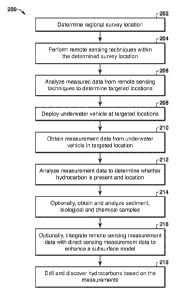
[0046] Figure 2 is a flow chart 200 for using remote sensing along with an
underwater
vehicle (UV) to perform hydrocarbon exploration in accordance with an
exemplary
embodiment of the present techniques. In this flow chart 200, various blocks
relate to
performing remote sensing on a survey location, such as blocks 202 to 206,
which may be
referred to as a remote sensing stage. Other blocks involve the more direct
measurements,
which involve the operation of an underwater vehicle, such as blocks 208 to
216, which may
be referred to as a direct sensing stage. Finally, block 218 relates to the
use of the measured
data for hydrocarbon discovery, which may be referred to as a discovery stage.
[0047] The remote sensing stage is described in blocks 202 to 206. At block
202, a
regional survey location is determined. In the exploration process, offshore
regions or large
areas that may have hydrocarbon potential are sometimes offered or awarded by
various
governments to companies for exploration purposes. Within these regions that
may include
sizes exceeding 100,000 km2, it is useful for companies to quickly and cost-
effectively
determine whether the region has the potential to yield hydrocarbon
accumulations (i.e.,
evidence within the region for an active hydrocarbon system) and, if so, to
locate and focus
on areas within the region that have the best exploration potential. Once the
regional survey
location is identified, remote sensing may be performed in the identified
survey location, as
shown in block 204. The remote sensing survey may include satellite imagery
and airborne
surveys along with water column surveys, as well. The remote sensing
techniques may
include the ocean acoustic waveguide; water column seismic; active acoustic
sensing
(multibeam echo sounder, two dimensional (2D) seismic, three dimensional (3D)
seismic,
sub-bottom profiler, side scan sonar, etc.); imagery and spectroscopy of
slicks and
atmospheric gas plumes (e.g., infrared (IR) to detect atmospheric gases, radar
reflectivity,
etc.); towed chemical sensors (mass spectrometer, etc.); passive acoustic
sensing; discrete
sampling from surface vessel of air, water, or soil at various locations; drop
and piston cores;
magnetic and gravity surveys; optical sensing; thermal anomalies detection;
and/or any other
remote sensing technique. These remote sensing techniques may be performed via
satellites,
16
CA 02853284 2014-04-23
WO 2013/071185 PCT/US2012/064548
airborne vessels, and/or marine vessels. Concurrently with collection of the
remote sensing
data or after the remote sensing measurement data is collected, the measured
data from the
remote sensing techniques may be analyzed to determine targeted locations, as
shown in
block 206. An example may include interpreting multibeam echosounder and sub-
bottom
profiler data acquired via a marine vessel. The multibeam backscatter data may
be examined
for anomalous sea-bottom hardness, roughness, and/or volumetric heterogeneity
in the
shallow sub-bottom and by examining the bathymetry data collected for local
highs, lows,
fault lines, and other geologic indicators that may be consistent with
permeable pathways for
hydrocarbon migration to the seafloor. In other words, these remote sensing
methods provide
targets for possible hydrocarbon seep locations. Similarly, if any slick data
from previous
satellite imagery interpretations are available or seismic data, etc. are
available, that
information may be integrated with the multibeam and sub-bottom profiler data
to improve or
"high-grade" the best locations for possible hydrocarbon seeps. Additionally,
interpretations
made from these results, preferable with the availability of seismic
information, may allow
geologic interpretations or models to be constructed about possible
hydrocarbon "plays" or
prospects, based on this initial information. These potential areas may again
be useful targets
to determine whether thermogenic hydrocarbons are present as seeps.
[0048] The direct measurements in the direct sensing stage, which involve the
operation
of an underwater vehicle, are described further in blocks 208 to 216. At block
208, the
underwater vehicle is deployed at the target location. The deployment may
include
transporting the underwater vehicle to the target location, which may be one
of various target
locations identified from the remote sensing survey. The underwater vehicle
may be
transported via another marine vessel and/or airborne vessel to the desired
target location.
The deployment may also include configuring the underwater vehicle to obtain
certain
measurements and/or to follow a certain search pattern. As may be appreciated,
the
configuration of the underwater vehicle may be performed prior to the
transporting of the
underwater vehicle to the target location, at least partially during the
transporting of the
underwater vehicle and/or at least partially at the target location.
Regardless, the
configuration of the undcrwater vehicle may include determining a sequence of
operations to
be performed by the underwater vehicle to perform the direct measurement
survey at the
target location. For instance, this configuring the underwater vehicle may
include
programming the navigation components to follow a general path, adjusting
operational
parameters and/or settings, adjusting the configuration of the monitoring
components, and/or
17
CA 02853284 2014-04-23
WO 2013/071185 PCT/US2012/064548
other suitable operational adjustments. This may also include inserting
certain equipment
(e.g., certain monitoring components) into the underwater vehicle for use in
monitoring..
Once configured, the underwater vehicle may be deployed into the body of
water, which may
include launching the underwater vehicle, and initiating underwater vehicle
measurement
operations. As an example, the deployment may include lowering the underwater
vehicle
from the deck of a marine vessel into the body of water or dropping the
underwater vehicle
into the body of water. The initiation of the measuring may be performed on
the vessel or
once the underwater vehicle is disposed in the body of water.
[0049] The operation of the underwater vehicle is described in blocks 210. As
may be
appreciated, the operation of the underwater vehicle, which may be an AUV, may
include
various processes that repeat during an operational period (e.g., period of
time that the
underwater vehicle is measuring data). During this operational period, the
underwater
vehicle may navigate toward targeted locations or may obtain measurements
along a specific
search pattern. To navigate, the underwater vehicle may utilize navigation
components,
which may include one or more propulsion components, one or more steering
components
and the like. The one or more propulsion components may include a motor
coupled to one or
more batteries and coupled to a propeller assembly, via a shaft, for example,
as is known in
the art. The propeller assembly may be utilized to move fluid in a manner to
move the
underwater vehicle relative to the body of water. The navigation components
may utilize
sensors or other monitoring devices to obtain navigation data. The navigation
data may
include different types of navigational information, such as inertial motion
unit (IMU), global
positioning system information, compass information, depth sensor information,
obstacle
detection information, SONAR information, propeller speed information,
seafloor map
information, and/or other information associated with the navigation of the
underwater
vehicle.
[0050] The underwater vehicle may obtain measurements within the target
location. For
example, the underwater vehicle may utilize the measurement components, such
as one or
more modules to receive measurement data and a process control unit to manage
the received
data, calculate operational and measurement parameters from the received data,
determine
adjustments to the operation of the underwater vehicle and determine if
additional
measurement information should be obtained. The measurement components may
include
fluorescence polarization components, fluorometric components, wireless
component (e.g.,
acoustic components and/or SONAR components), methane or other chemical
compound
18
CA 02853284 2014-04-23
WO 2013/071185 PCT/US2012/064548
detection components, temperature components, camera components and/or other
measurement components. The measurement data may include camera images, SONAR
data
and/or images, acoustic data, temperature data, mass spectrometric data,
conductivity data,
fluorometric data, and/or polarization data, for example. The data can be in
the format of
.. images, raw data with specific format for the component, text files, and/or
any combination
of the different types. The underwater vehicle may include integrated sensor
payloads that
are utilized to monitor a large area, while two or more AUVs, which may
communicate
between each other, may also be utilized in other applications to monitor
other areas that may
be smaller in extent. Other sensors may include functionality to provide
chemical specificity
.. of applied sensors (e.g., underwater mass spectrometry). These sensors may
discriminate
thermogenic hydrocarbons, which may be preferred, from biogenic hydrocarbons
and may
determine whether the seep is associated with gas, oil, or a combination of
gas and oil. As an
example, the underwater vehicle may be an AUV. The AUV may include artificial
intelligence that is configured to detect and navigate toward peak
concentrations of targeted
.. chemicals, such as propane, and data reporting is done periodically to a
small surface vessel
or to shore using satellite links.
[0051] Once the measurement data is obtained, it may be analyzed to determine
whether
hydrocarbons are present and their location, as shown in block 212. As the
measurement data
may include various forms, the measurement data may be analyzed on the
underwater vehicle
.. via the respective measurement equipment and/or transmitted to another
location for
processing. Certain of these aspects are discussed below.
[0052] At block 214, the sediment, biological and chemical samples may be
obtained and
analyzed to further enhance the process. Sediment samples may be acquired by
ship-based
drop or piston core surveys, based on the integration of the remote sensing
and direct
.. measurement information (e.g., sub-bottom profile and seismic data linked
to seep locations),
which may greatly improve the ability to collect meaningful sediment samples
that contain
hydrocarbons. These samples are then analyzed (which may be in a laboratory or
onboard a
vehicle) using fluorometry, gas chromatography (GC), and more sophisticated GC-
MS (mass
spectrometry)-MS or GC-GC time of flight mass spectrometry or additional
techniques to
.. obtain biomarkers and other indicators of hydrocarbon source facies and
thermal maturity.
The samples may also be obtained via underwater vehicle. In particular, this
method may
include determining the presence and estimating information, such as depth,
type, quality,
volume and location, about a subsurface hydrocarbon accumulation from the
measured data
19
CA 02853284 2014-04-23
WO 2013/071185 PCT/US2012/064548
from the samples acquired by the underwater vehicle. The samples may be
subjected to three
independent analysis technologies, such as clumped isotope geochemistry, noble
gas
geochemistry, and microbiology. These may each be utilized to provide
additional
information about the depth, fluid type (oil vs. gas) and quality, and volume
of subsurface
hydrocarbon accumulations. That is, the method may integrate existing and new
biological
and geochemical indicators to provide insights in opportunity identification.
In addition, the
integration of these biological and geochemical indicators with
geological/geophysical
contextual knowledge with the other geological and measurement data further
provides
enhancements to hydrocarbon opportunity identification. These analysis
techniques are
described in U.S. Patent No. 61/595,394; U.S. Patent No. 61/616,813; and U.S.
Patent No.
61/558,822.
[0053] The remote sensing measurement data may be integrated with the direct
sensing
data to enhance a subsurface model, as shown in block 216. As an example, the
measured
data may be organized with the location of the underwater vehicle or a
location to correlate
the measured data with other surveys of the subsurface geology. As a specific
example,
multi-beam echo sounding data may be associated with the location of a surface
vehicle and
used to detect sea bottom topography, texture, and density, and SBP (sub-
bottom profiler) to
locate shallow subsurface gas anomalies and hydrate layers associated with
bottom
simulating reflectors. The measured data from chemical sensors associated with
an
underwater vehicle may be used to locate anomalous chemistries associated with
seeps and
seep vents, to map these anomalies relative to geologic features, and to
distinguish
thermogenic from biogenic gas, and gas from oil. These different types of data
may be
integrated based on location information associated with the respective data
to provide
additional information. Chemical results from drop or piston core surveys are
further
integrated with seismic, gravity, and magnetic data that have been combined to
create
subsurface models of the geology and hydrocarbon system in a region. The
subsurface
models are further enhanced by the results of microbial ecology, clumped
isotopes, and noble
gas signatures from samples acquired by an underwater vehicle.
[0054] Finally, block 218 relates to the designation of a drilling
location for discovery of
hydrocarbons based on the measured data. The discovery of hydrocarbons is
based on a
determination that is made whether to access hydrocarbons from the target
locations based at
least partially on the measured data or the integrated data. The determination
may include
analyzing the measured data for one or more of the hydrocarbon accumulation
type, quality,
CA 02853284 2014-04-23
WO 2013/071185 PCT/US2012/064548
depth and volume obtained from the microbial ecology, clumped isotope and
noble gas
signatures and/or these data integrated with the geological and geophysical
data. The
discovery of the hydrocarbons involves drilling a well to provide access to
the hydrocarbon
accumulation. Further, the production may include installing a production
facility is
configured to monitor and produce hydrocarbons from the production intervals
that provide
access to the subsurface formation. The production facility may include one or
more units to
process and manage the flow of production fluids, such as hydrocarbons and/or
water, from
the formation. To access the production intervals, the production facility may
be coupled to a
tree and various control valves via a control umbilical, production tubing for
passing fluids
from the tree to the production facility, control tubing for hydraulic or
electrical devices, and
a control cable for communicating with other devices within the wellbore.
[0055] Beneficially, this integrated method provides an enhancement in the
exploration of
hydrocarbons. In particular, the method may be utilized prior to drilling
operations to reduce
exploration risk by providing more information about the presence and location
of
thermogenic hydrocarbon seepages from the seafloor. As a result, this method
provides a
cost-effective technique to enhance basin assessment and to high-grade areas
for exploration.
The analysis of seismic, gravity, magnetics, and acoustic data from surface
surveys, plus
integrated interpretation of physical and chemical data from underwater
vehicles, provides an
enhanced method to locate seafloor seeps of thermogenic hydrocarbons cost-
effectively over
large areas.
[0056] Further, mapping of anomalies around hydrocarbon seeps may be useful to
locate
areas where fluids are exiting the subsurface onto the seafloor. This approach
may be
utilized to enhance other technologies, such as drop core sampling of
hydrocarbon-associated
sediments, or the acquisition of fluids or gases above, at, or under the
seafloor. Accordingly,
this integrated method may be utilized to further enhance the exploration
activities.
[0057] As another specific embodiment, Figure 3 is a flow chart 300 for using
remote
sensing along with an underwater vehicle (UV) to perform hydrocarbon
exploration in
accordance with another exemplary embodiment of the present techniques. In
this flow chart
300, various blocks relate to the remote sensing stage, direct sensing stage
and discovery
stage, as noted above in Figure 2, and are utilized to determine the location
of a hydrocarbon
seep. In this flow chart 300, the remote sensing stage may include blocks 302
to 310, the
direct sensing stage may include blocks 312 to 318 and the discovery stage may
include
blocks 320 to 322.
21
CA 02853284 2014-04-23
WO 2013/071185 PCT/US2012/064548
[0058] The remote sensing stage is described in blocks 302 to 310. At block
302, imagery
and spectroscopy of slicks and atmospheric gas plumes is performed. For
example, these
tools may include high resolution satellite, radar (e.g., synthetic aperature
radar) and ultra-
violet imagers that can detect the presence and geographic extent of oil
slicks. Multi-spectral
imaging data can also be used to map large oil-slicks that occur offshore. As
another
example, infrared sensing may be utilized to detect atmospheric gases, radar
reflectivity;
and/or airborne surveys. Then, at block 304, a regional survey location may be
utilized to
identify one or more target location within the region. This determination may
include
identifying a region that has potential to include one or more hydrocarbon
seeps based on the
imagery and spectroscopy data.
[0059] Once the regional survey location is identified, the remote sensing
may be
performed via a marine vessel, as shown in block 306, and via the underwater
vehicle, as
shown in block 308. At block 306, remote sensing data is obtained from a
surface marine
vehicle, such as a surface vessel. The remote sensing data from the surface
vessel may
include performing active acoustic sensing (e.g., multibeam echo sounder, 2D
seismic, 3D
seismic, sub-bottom profiler, side scan sonar, etc.), chemical analysis (e.g.,
towing in situ
chemical sensors (mass spectrometer, etc.)); discrete in situ sampling from
surface vessel of
air, water, or soil at various locations; drop or piston cores, sampling
system; pumping liquid
to sensing location, passive acoustic techniques; magnetic and gravity
surveys; optical
sensing (remote or in situ); thermal anomalies analysis; any other remote or
in situ sensing
technique. At block 308, the remote sensing data from the underwater vehicle
(e.g.,
underwater deployment device (AUV, ROV, floats, any other underwater
deployment
device); may include analyzing of sediment or water samples. Then, at block
310, the
specific locations for sediment, biological and chemical sampling (e.g.,
target location) are
determined to further enhance the analysis. This determination may include
identifying
target locations for focused investigations of points of interest to confirm
presence of
thermogenic hydrocarbon seepage (e.g., molecular geochemistry of seafloor
sediments, water
column, etc.).
[0060] The biological and chemical sampling in the direct sensing stage is
performed at
blocks 312 to 318. The sample is obtained in block 312. The location of the
hydrocarbon
sample may be based on a known seep location or determining a seep location
through
known techniques. The one or more samples are obtained from the hydrocarbon
sample
location. If the hydrocarbon location is a seep, the sampling of seep
locations may include (i)
CA 02853284 2014-04-23
WO 2013/071185 PCT/US2012/064548
confirming the presence of hydrocarbons (e.g., biogenic, thermogenic,
abiogenic) at the seep
location and (ii) conducting advanced biological and geochemical analysis
after appropriate
sampling. The sampling methods used to collect the samples of interest may
include gravity
or piston drop core sampling, the use of manned submersibles, autonomous
underwater
vehicles (AU V) or remotely operated vehicles (ROV) with coring sampling
devices, and gas
sampling apparatus. Sampling may also include collection of surface sediments
surrounding
the seep location and collection of fluids from within the seep conduit. A
sample can
comprise (i) any surface sample, such as a sediment sample taken from the sea-
floor or a
sample of seeped fluids, (ii) any sample taken from the water column above a
seep location,
or (iii) any sample taken from within the seep conduits below the surface.
Identification of
the presence of hydrocarbons may be determined by standard geochemical
analysis. This may
include but is not restricted to maximum fluorescence intensity and standard
molecular
geochemistry techniques such as gas chromatography (GC). For biology samples,
appropriate preservation should be taken, as is known in the art. Similarly,
gas and/or oil
samples that are subjected to clumped isotope and noble gas analysis may be
collected using
funnels or inserted into seep conduits connected to sampling cylinders.
[0061] After the sample obtaining stage, the molecular and isotopic signatures
of non-
hydrocarbon gases and hydrocarbons in the sample are measured, as shown in
block 314. In
particular, the molecular and isotopic signatures of non-hydrocarbon gases
(e.g. H2S, CO2,
N7) and hydrocarbons are measured, which includes the analysis of noble gas
signatures (He,
Ne, Ar, Kr and Xe) and the isotopologue or clumped isotope signature of both
non-
hydrocarbon and hydrocarbon molecules (in gases, water, and/or oils).
Isotopologues are
molecules that differ only in their isotopic composition. Clumped isotopes are
isotopologues
that contain two or more rare isotopes. The sample of interest may comprise
water, oil,
natural gas, sediments or other types of rocks, or fluids present in
sediments, rocks, water or
air. Measurement of the abundance of each noble gas isotope can be conducted
following
standard extraction techniques using mass spectrometry. Measurement of the
abundance of
each clumped isotope or isotopologue can be conducted using multiple
techniques, such as
mass spectrometry and/or laser-based spectroscopy. The ecology of samples
(e.g., sediment,
seawater, seeped fluids and the like) can be characterized through a number of
different
techniques. These may include but are not restricted to deoxyribonucleic acid
(DNA)
analysis, ribonucleic acid (RNA) analysis, (meta) genomics, (meta) proteomics,
(meta)
transcriptomics, lipid analysis, and culture-based methods. The analysis may
include both
CA 02853284 2014-04-23
WO 2013/071185 PCT/US2012/064548
(semi) quantitative (e.g., qPCR (quantitative polymerase chain reaction), next-
generation
sequencing) and qualitative assessments (e.g., sequencing, microscopy,
phenotype tests).
Standard molecular analysis is conducted to characterize the organic signature
of
hydrocarbons extracted from the sample. Analysis may include the use of gas
chromatography-mass spectrometry (GC/MS), GC/GC/MS, and liquid chromatography.
Inorganic analysis of samples may also be conducted. Analysis may include but
is not
restricted to inductively coupled plasma mass spectrometry (ICP-MS) and ICP-
optical
emission spectroscopy. Gas chemistry analysis may also be conducted and may
include
isotope ratio ¨ mass spectrometry and GC.
[0062] At block 316, the interpretation of advanced molecular and isotopic
signatures,
including noble gas signatures and clumped isotope signatures of hydrocarbon
and non-
hydrocarbon molecules is performed. This interpretation involves determining
the type and
quality of hydrocarbons and/or depth of a hydrocarbon accumulation and/or
volume of a
hydrocarbon accumulation. As an example, the noble gases may be utilized to
determine
hydrocarbon accumulation volume, hydrocarbon type and oil quality and is
provided in a
U.S. Patent No. 61/616,813. As natural gases and oils are initially devoid of
noble gases, the
addition of these through interaction with formation water provides
information about the
samples. The impact of this interaction on isotopic ratios and absolute
concentrations of
noble gases present in the hydrocarbon phase is a function of three variables:
(i) the initial
concentration and isotopic signature of noble gases in the water phase, (ii)
the solubility of
noble gases in water and oil (solubility of noble gases in oil is controlled
by oil quality), and
(iii) the ratio of the volumes of oil/water, gas/water or gas/oil/water.
[0063] The initial concentration of noble gases in the water phase prior
to interaction with
any hydrocarbons can be accurately measured or estimated. Noble gases dissolve
in water
during recharge from meteoric waters or at the air/water boundary for
seawater. This initial
signature is therefore dominated by atmospheric noble gases, namely 20Ne,
36Ar, 84Kr and
132Xe. The amount of noble gases that dissolve into the water phase obeys
Henry's Law,
which states that the amount of noble gases dissolved in water is proportional
to the partial
pressure of the noble gases in the atmosphere (which varies as a function of
altitude for
meteoric water recharge). The Henry's constant is directly related to the
salinity of the water
phase and the ambient temperature during the transfer of noble gases to the
water. Formation
waters recharged from meteoric waters at the air/soil interface may have an
additional
component of atmospheric derived noble gases from that which is expected
purely from
24
CA 02853284 2014-04-23
WO 2013/071185 PCT/US2012/064548
equilibrium, "excess air". These influences may be subject to adjustments
(e.g., correction
schemes, such as those noted in Aeschbach-Hertig, W., Peeters, F., Beyerle,
U., Kipfer, R.
Palaeotemperature reconstruction from noble gases in ground water taking into
account
equilibrium with entrapped air. Nature, 405, 1040-1044, 2000, for example).
The resulting
noble gas signature therefore lies between air-saturated water (ASW), air-
saturated seawater
(ASS) and air-saturated brine (ASB) for any given temperature. Radiogenic
noble gases are
then introduced following recharge through radioactive decay of minerals
within the
subsurface. The concentration of the radiogenic noble gases typically
increases with
increasing formation water residence time (or age). This evolving noble gas
signature in the
water phase is changed as a result of mixing and interaction with other
fluids.The solubilities
of noble gases in water have been determined for a range of different
temperatures, as is
known in the art (e.g., Crovetto, R., Fernandez-Prini, R., Japas, M.L.
Solubilities of inert
gases and methane in H20 and D20 in the temperature range of 300 to 600K,
Journal of
Chemical Physics 76(2), 1077-1086, 1982; Smith, S.P. Noble gas solubilities in
water at high
temperature. EOS Transactions of the American Geophysical Union, 66, 397,
1985.).
Similarly, the measured solubility of noble gases in oil increases with
decreasing oil density
(Kharaka, Y.K. and Specht, D.K. The solubility of noble gases in crude oil at
25-100oC.
Applied Geochemistry, 3, 137-144, 1988.). The exchange of atmospheric noble
gases
between formation water and both the oil and/or gaseous hydrocarbon phase can
occur
through various processes, and the extent of fractionation induced by each of
these processes
gives rise to different signatures in the different phases. These processes
can be modeled and
may comprise equilibrium solubility, Rayleigh style fractionation and gas
stripping. The
exchange of noble gases between oil and water may result in the oil phase
developing an
enrichment in the heavy noble gases (Kr and Xe), and an associated depletion
in the light
noble gases (He and Ne) relative to the water phase. This is because of the
greater solubility
of the heavier noble gases in oil than in water. In contrast, the interaction
of a gas phase with
water may result in the gas phase becoming relatively enriched in the lighter
noble gases and
depleted in the heavy noble gases relative to a water phase. The magnitude of
this
fractionation may change depending upon the exchange process involved and on
the density
of the oil phase
[0064] Assuming that a subsurface signature is preserved during migration to
the surface,
the phases that interacted (e.g. oil-water, gas-water or gas-oil-water) with a
seeped
hydrocarbon by measuring the concentration of noble gases in the hydrocarbon
sample may
CA 02853284 2014-04-23
WO 2013/071185 PCT/US2012/064548
be determined. The noble gases provide a conservative tracer of the
hydrocarbon type present
within the subsurface (oil vs. gas). Knowledge of the solubility of noble
gases as a function
of oil density provide further information about the estimate of the oil
quality when the
hydrocarbon present is determined to be oil. Finally, given that two of the
three variables
that control the exchange of noble gases between water and hydrocarbons are
known or can
be modeled, the hydrocarbon/water volume ratio within a subsurface hydrocarbon
accumulation can be determined. From this it is possible to quantitatively
predict the volume
of hydrocarbon present within a subsurface accumulation.
[0065] In addition to the utilization of noble gases to determine
hydrocarbon
accumulation volume, hydrocarbon type and oil quality, the clumped isotope
geochemistry
may be utilized to determine the depth of a hydrocarbon accumulation. As an
example, U.S.
Patent No. 61/558,822 describes a process for determining the clumped isotope
signature of
any molecule. The clumped isotope signature of any molecule is a function of
(i)
temperature-independent randomly populated processes (e.g., stochastic
distribution) and (ii)
thermal equilibrium isotopic exchange. The latter process is controlled or
dependent on the
surrounding temperature. The stochastic distribution of any isotopologue can
be determined
from the bulk isotope signatures of the species from which it derives. For
example,
determining the stochastic distribution of isotopologues for methane requires
knowledge of
the 13C and D signatures of methane. The isotopic signature of hydrocarbon
gases that are
stored in a subsurface accumulation or that are present at seeps may reflect
the isotopic
signature of the gas generated from the source rock. As such, this signature
may be
concomitantly determined during the characterization of the hydrocarbons
present at a seep
and substituted directly in to the calculation of the stochastic distribution.
There may be
occasions, however, when the isotopic signature of gases is altered by
processes like mixing
with biogenic gas. In such instances, correction schemes known in the art may
be relied upon,
such as Chung et al., (1988; H.M. Chung, J.R. Gormly, R.M. Squires. Origin of
gaseous
hydrocarbons in subsurface environments: theoretical considerations of carbon
isotope
distribution in M. Schoell (Ed.), Origins of Methane in the Earth. Chem.
Geol., 71 (1988), pp.
97-103 (special issue)). The correction scheme may be used to deconvolve such
contributions and reach the initial primary isotope signature that should be
used in the
calculation of the stochastic distribution.
[0066] The expected increased abundance, or enrichment, of any given
isotopologue or
clumped isotope can be modeled or empirically determined for any given
temperature. By
CA 02853284 2014-04-23
WO 2013/071185 PCT/US2012/064548
measuring the clumped isotope and isotopologue signatures of a given molecule,
and through
knowledge of the stochastic distribution, the enrichment of the measured
concentrations
relative to the stochastic distribution can be used to determine the
temperature in the
subsurface from which this molecule is derived.
[0067] Hydrocarbons that derive from a subsurface accumulation may retain a
clumped
isotope signature that more reflects the temperature at which the hydrocarbons
were stored in
the subsurface. This non-kinetic control on the isotopic exchange reactions in
isotopologues
of hydrocarbons that originate from a subsurface accumulation arises as a
result of the
inherently long residence times of hydrocarbons in the subsurface. Through
application of a
suitable geothermal gradient to the storage temperature derived from the
clumped isotope
signature, the location (depth) within the subsurface that seep-associated
hydrocarbon
accumulations reside may be estimated.
[0068] As another independent technique useful for the detection of
hydrocarbon
accumulations and their location or depth, the microbial ecology and biomarker
signature of
hydrocarbon seeps may be used to determine the depth of a hydrocarbon
accumulation and/or
the hydrocarbon accumulation volume and/or the hydrocarbon type and oil
quality, as
described in U.S. Patent No. 61/595,394. Ecology is the study of interactions
between living
organisms and the non-living surrounding environment. Microbial ecology refers
to the
ecology of small organisms like bacteria and archaea. Ecology includes biotic
parameters like
community composition (e.g., which organisms are present), community function
(e.g., what
those organisms are doing), organism behavior, organism quantity and
metabolite production.
Additionally, ecology includes abiotic parameters like pH, temperature,
pressure and aqueous
concentrations of different chemical species. We may measure all or some of
these
parameters to describe the ecology of a hydrocarbon seep. Seeps that are
connected to
hydrocarbon accumulations may have different ecologies than seeps that are not
connected to
hydrocarbon accumulations.
[0069] Microbial ecology involves using genomics and culture based techniques
to
describe the community composition. (Meta) Genomics, (meta) transcriptomics,
(meta)
proteomics and lipid measurements can be combined with chemical measurements
to
determine the community function. Changes in temperature drive changes in
community
structure and function. Changes in hydrocarbon type and volume present in the
accumulation
change community structure and function. If a seep is connected to a
hydrocarbon
27
CA 02853284 2014-04-23
WO 2013/071185 PCT/US2012/064548
accumulation, these ecological differences may be reflected in samples
acquired from the
seep.
[0070] The sediment and fluid samples from in and around a hydrocarbon seep
may be
collected and appropriately preserved. Changes in the ecology of these samples
may reflect
the conditions of the subsurface accumulations feeding the seeps. Samples from
a seep not
connected to a hydrocarbon accumulation may not contain ecological parameters
associated
with a deep hot hydrocarbon environment.
[0071] Then, at block 318, the hydrocarbon accumulation type and quality,
depth and
volume obtained from the microbial ecology, clumped isotope and noble gas
signatures may
be integrated with remote sensing data obtained from remote sensing, as noted
in blocks 302
to 310, to confirm accumulation materiality. This integration step includes
incorporation all
aspects of the hydrocarbon system model along with geological and geophysical
data, such as
basin modeling, and/or probabilistic or statistical risk assessments. Included
in this
assessment are the risks of adequate source, maturation, migration, reservoir
presence and
quality, trap size and adequacy, and seal. If aspects of the risk assessment,
including the
results of blocks 312 to 318, are sufficiently favorable, a decision as to
whether to stop or
continue the process remains.
[0072] The discovery stage includes blocks 320 to 322. At block 320, a
determination to
access the hydrocarbons based on the measured data and the integrated data is
made. This
determination may include a variety of economic factors that include the
associated costs of
drilling a well versus the economic benefits of discovering an accumulation of
the size
expected at the depth expected incorporating appropriate risks. If the cost
benefit is deemed
sufficient, then, at block 322, a well is drilled and hydrocarbons are
discovered based on the
determination. This discovery of hydrocarbons may be similar to block 218 of
Figure 2.
[0073] As noted above, these remote sensing and direct measurements may be
performed
by an underwater vehicle and/or a marine vessel. The measurements may include
detecting
seep locations via a high-resolution multi-beam survey, as described in
Valentine et al.
(2010; Valentine DL, Reddy CM, Farwell C, Hill TM, Pizarro 0, Yoerger DR,
Camilli R,
Nelson RK, Peacock EE, Bagby SC, Clarke BA, Roman CN, Soloway M. Asphalt
Volcanoes as a Potential Source of Methane to Late Pleistocene Coastal Waters.
Nature
Geoscience Letters. DOT: 10.1038,NGE0848)) in the Santa Barbara basin. While
certain
measurements may be performed via a surface vessel, the costs of doing
regional surveys
with towed tools, especially at depths greater than a few hundred meters, are
very high due to
CA 02853284 2014-04-23
WO 2013/071185 PCT/US2012/064548
the limited speeds that can be achieved while keeping the device near the
seabed with
manageable tension loads on the support cable. The typical spatial resolution
achieved with
these towed systems is also low (e.g., on the order of hundreds of meters),
compared to the
approximate ten meter spatial resolution obtained by using a mass spectrometer
and
fluorometer incorporated into an underwater vehicle (e.g., AUV). There is also
the added
complexity and potential source of error that may occur if water samples are
collected for
shipboard analysis and have not maintained their in situ properties.
[0074] To enhance the measurement data, an underwater vehicle may be used to
obtain
certain data. The underwater vehicle may include an AUV, ROV, towfish or
manned
submersibles. The different configurations of these AUVs and method of
operation may
include various different combinations of components to provide the
measurement data for a
specific survey. The different configurations may be utilized to perform the
direct
measurements of the target locations, as noted above. These measurements may
include
analysis of gases or water soluble hydrocarbons dissolved in water as well as
phase-separated
pockets of hydrocarbons in the water. In addition, the direct measurements may
include
information about geological features associated with active hydrocarbon seep
locations.
These underwater vehicles are known in the art, as noted above with regard to
pipeline leak
detection. See; e.g., R. Camilli, A. Duryea 2007., in Proc. IEEE/MTS OCEANS
(IEEE/MTS,
Vancouver, Canada, 2007), pp. 1-7 (10.1109/OCEANS.2007.4449412).
[0075] As an example, underwater vehicles may include various different
chemical
sensors. Specifically mass spectrometry and fluorometry may be utilized to
conduct surveys
to locate hydrocarbons in the marine environment. To enhance the hydrocarbon
survey
techniques, an AUV may be utilized in a system that can be programmed to
conduct
autonomous missions to any depth of exploration interest. That is, the system
may obtain
measurement data near the seafloor that results in unsurpassed seafloor, sub-
bottom, and in
situ water chemistry resolution in near real time. This real time acquisition
may provide
additional clarification as to the location of the hydrocarbons.
[0076] In another example, the underwater vehicle may include a methane sensor
to detect
the presence of hydrocarbons near the seabed. This underwater vehicle may also
include
gravity and magnetic sensors to perform additional data that may be correlated
to the
methane sensor data. To provide additional enhancements, the measured data may
be
organized with the location of the underwater vehicle to correlate the
measured data with
other surveys of the subsurface geology. The chemical sensors can be used to
locate
29
CA 02853284 2014-04-23
WO 2013/071185 PCT/US2012/064548
anomalous chemistries associated with seeps and seep vents, to map these
anomalies relative
to geologic features, and to distinguish thermogenic from biogenic gas, and
gas from oil.
Further, sensors may also be utilized to provide chemical and isotopic
analysis of
hydrocarbons to determine whether a seep source is thermogenic or biogenic.
Each of these
different sensors may be included in the underwater vehicle to provide
enhancements to the
measured data collected and analyzed.
[0077] Accordingly, in certain embodiments, underwater vehicles (e.g.,
unmanned
underwater vehicle) may include sensors capable of detecting chemical or
physical anomalies
that are indicative of hydrocarbon seeps and correlating them to a specific
location. The
chemical specificity of applied sensors, particularly underwater mass
spectrometry
supplemented by a flourometer, may also provide the discrimination of
thermogenic seeps
from biogenic seeps and to determine whether the seep is associated with gas,
oil, or gas and
oil. The sensors may include a mass spectrometer, a methane detector,
fluorometer,
multibeam echo sounder (MBES), sub-bottom profiler (SBP), side-scan sonar
(SSS), and
camera [this has been done to some extent in oceanographic research].
Regardless, the
sensors may be utilized to map the hydrocarbon types and concentrations, which
may be
utilized to indicate the presence and surface-subsurface linkages to a
hydrocarbon system. In
addition, the sensors may differentiate biogenic hydrocarbons from thermogenic
hydrocarbons, oil from gas, and provide additional information regarding
locations for drop
cores or piston cores, and further sampling.
[0078] The underwater vehicle provides an enhancement to the ability to locate
hydrocarbon seeps efficiently and in a cost-effective manner for a large
region. This is
accomplished through a combination of direct measurements with the remote
sensing
instruments. In this manner, the subsurface models can be enhanced and reduce
exploration
risk. Further, this acquisition of this direct measurement data may be
performed
inexpensively and efficiently at regional scales. As a result, the exploration
process may be
enhanced to improve the ability to find and prioritize play extensions.
[0079] As an example of an AUV, Figure 4 is a diagram of an AUV in accordance
with an
exemplary embodiment of the present techniques. In this AUV 400, a process
control unit
402 is utilized to manage the navigation components and the measurement
components. The
process control unit 402 includes a processor 403, memory 404 and sets of
instructions (e.g.,
master navigation module 410 and master measurement module 420) that are
stored in the
memory 404 and executable by the process control unit 402. The power for the
process
CA 02853284 2014-04-23
WO 2013/071185 PCT/US2012/064548
control unit 402 may be supplied by one or more batteries 406. Also, the
process control unit
402 may include a communication component 408, which may include an antenna
and other
equipment to manage communications with other systems, such as marine vessel
and/or GPS.
[0080] The navigation components of the AUV 400 may include the master
navigation
module 410, a mapping component, such as SONAR component 412, motion sensor
component 416 and propulsion component 418. The master navigation module may
operate
by the processor executing the sets of instructions configured to: manage the
different
navigation components, calculate the path of the AUV, obtain signals (e.g.,
GPS signals
and/or wireless guidance signals), communicate with the propulsion systems to
adjust
steering and/or speed of the AUV, obtain motion sensor data, and/or calculate
the AUV's
location based on different data (e.g., GPS data, wireless guidance data,
motion sensor data
and mapping component data). The SONAR component 412 may include SONAR sensor
equipment to send and receive SONAR signals and provide associated SONAR data
to the
master navigation module. The SONAR component 412 may also be utilized for the
detection of hydrocarbons external to the AUV (e.g., in fluid disposed
external to the AUV,
such as a body of water that the AUV is disposed within). The motion sensor
component 416
may include various sensors and other equipment to obtain motion sensor data
about the
forces applied to the AUV 400 (e.g., currents and fluid flows). The motion
sensor component
416 may include a processor that communicates with a gyroscope, depth sensor,
velocity
meter along with various other meters to measure the orientation or other
parameters of the
AUV. Also, the propulsion component 418 may include two propeller assemblies
enclosed
by a propeller support member, a motor coupled to the batteries 406.
[0081] The measurement components of the AUV 400 may include the master
measurement module 420, resistivity components 422a-422c, camera component
424a-424c
and/or other hydrocarbon detection component 426 along with the SONAR
component 412.
The master measurement module may operate by the processor executing the sets
of
instructions configured to: manage the different measurement components,
determine
whether hydrocarbons are present external to the AUV (e.g., in fluid disposed
external to the
AUV, such as a body of water that the AUV is disposed within), communicate
with the
propulsion systems to adjust steering and/or speed of the AUV if hydrocarbons
are detected,
obtain measurement data and the AUV's location based on different hydrocarbon
indications,
and store certain measurement data and AUV location data. The resistivity
components
31
CA 02853284 2014-04-23
WO 2013/071185 PCT/US2012/064548
422a-422c may include various sensor that are configured to detect resistivity
via contact
with the fluid adjacent to the AUV and provide these measurements to a
processor, which is
configured to send and receive commands, process the resistivity data and to
communicate
resistivity data and/or certain notifications with the master measurement
module 420. The
camera components 424a-424c may include various cameras that are configured to
obtain
images (e.g., the images may be subjected to different filters) of fluids,
bathymetric features,
biologic communities, bubbles, etc. adjacent to the AUV path and provide these
images to a
processor, which is configured to send and receive commands, process the
images, and to
communicate camera data and/or certain notifications with the master
measurement module
420. The other hydrocarbon detection components 426 may include various piping
and
equipment that is utilized to obtain measurement data near the AUV. The other
hydrocarbon
detection components may include fluorescence polarization component,
fluoromctric
component, wireless component (e.g., acoustic component and/or SONAR component
412),
methane component, temperature component, mass spectrometer component and/or
other
suitable measurement components. For example, a temperature component
typically has a
thermocouple or a resistance temperature device (RTD). The measurement data
may include
acoustic images, acoustic data, temperature data, fluorometric data, and/or
polarization data,
for example. The other hydrocarbon detection components 426 may also include a
processor
configured to send and receive commands, to process the measured data, and to
communicate
measured data and/or certain notifications with the master measurement module
420.
[0082] The equipment within the AUV 400 may be coupled together through
physical
cables to manage the distribution of power from the batteries 406 and to
manage
communication exchanges between the equipment. As an example, power
distribution is
provided between the process control unit 402, the one or more batteries 406
and the
communication component 408 via lines 409, while the communication
distribution is
provided between the process control unit 402 and the communication component
408 via
line 407. Other communication and power distribution lines are not shown for
simplicity in
this diagram. Also, the communication between certain devices may be via
wireless
communications, as well. Accordingly, the specific configuration with the AUV
provides
flexibility in obtaining different types of data, which may be managed for
certain locations.
[0083] Multiple different sensors may be preferred to further verify the
measured data
from one of the sensors. For example, the presence of methane alone does not
provide the
32
CA 02853284 2014-04-23
WO 2013/071185 PCT/US2012/064548
clear indication of a biogenic gas from thermogenic gas and whether wet gas
and/or oil are
present. Biogenic gas is not generally a conventional exploration target,
although it can be
exploited in some environments. The formation of biogenic gas is related to
methanogenic
bacteria that in some cases reduce CO2 and oxidize organic matter to produce
only methane
in shallow environments. As such, it is most common to find small amounts of
methane (CI)
in shallow marine sediments that are insignificant for exploration purposes,
effectively acting
as a "contaminant" in the absence of other hydrocarbon indicators. Conversely,
thermogenic
gas is generated from an organic rich source rock at depth that produces a
host of
hydrocarbon gases (C1-05) and heavier liquids (oil). The mass spectrometer is
capable of
analyzing for methane, ethane, propane, and higher hydrocarbons (up to 200
atomic mass
units) that provides a distinction between biogenic and thermogenic gas, gas
wetness, and
whether a seep is related primarily to oil, gas, or both a combination of oil
and gas. The
flourometer supplements the mass spectrometer by indicating the presence of
aromatic
compounds consistent with liquid-rich hydrocarbons.
[0084] While the mass spectrometer has the capability of analyzing masses to
200 amu,
the sensitivity to lower atomic masses (e.g., <70 amu) is greater. As a
result, certain lighter
masses (actually mass/charge ratio or m/z) that are generally distinctive for
a compound of
interest for hydrocarbon exploration may be useful in hydrocarbon exploration.
These
masses or their ratios relative to a mass that remains generally constant in
water are utilized.
For example, water with mass 17 represented by 1601H+ is commonly chosen for
this
purpose. There is also the added complexity of certain masses not being
uniquely distinctive
for a single compound. An example is mass 16, which is both a primary mass
indicator for
methane (12C11-14) and oxygen (160). To avoid significant contributions from
interfering
compounds, methane is measured at mass 15 rather than 16, and commonly
compared to
mass 17, or amu ratio 15/17 is used to indicate methane amount for a
particular measurement.
This ratio assumes that any fluctuation in the water ion peak is due to
variability in
instrument response (e.g., instrument drift) because the concentration of
water in water is
well known. Some commonly used masses (or ratios relative to mass 17) of
importance are
listed below in Table 1.
Table 1. Commonly used masses (mass/charge ratio) for locating and
characterizing
hydrocarbon seeps
miz Interpreted Compound Abbreviation
4 Helium (Hex) He
14 Nitrogen (N+ and N,++) plus some methane and ethane NIT
33
CA 02853284 2014-04-23
WO 2013/071185
PCT/US2012/064548
15 Methane (or methyl C1 fragment) (CH3 ') MTH or Cl
17 Water (1601H') H20
20 Water (H2180+)
22 Carbon dioxide (CO2
28 Nitrogen (N2')
30 Ethane (or ethyl C2 fragment) (C2H6'); ethane sometimes ETH
or C2
g27
32 Oxygen (1602)
02
34 Hydrogen sulfide (H,S ') and oxygen 160180 H2S
39 Propane (C3H8) various fragments PRO
40 Argon (Art) Ar
41 Propane (or propyl C3 fragment) (C3H7 '); propane C3+
sometimes measured g39 or 43 if no major interferences
(e.g., from CO2+@ 44)
44 Carbon dioxide (CO2) CO2
55 Naphthene C4 fragment (C4H7) NAP
57 Paraffin C4 fragment (C4H9+) PAR
58 Various "butane" fragments (C4H10) BUT
60 Acetic acid (CH3C00FL), or from carbonyl sulfide HAC
(COS)
78 Benzene (C6H6+) BEN
91 Toluene (C7H7) TOL
97 Alkylated Naphthene (C7H13+) ANP
106 Xylene (C8H10+) XYL
[0085] The mass spectrometer housed within an AUV may provide the rapid
measurement of masses in the range of 1 amu to 200 amu for a water sample
about every five
seconds, depending on water depth. The presence of C1, C?, C3 paraffins,
naphthenes, and
the aromatics benzene and toluene (sometimes xylene), as well as the non-
hydrocarbon gases
CO?, 1-17S, N2, Ar, and He, or their ratios, provides beneficial
interpretations to be made
regarding the location and characterization of hydrocarbon seeps. A biogenic
gas consists
only of methane (occasionally very small amounts of ethane) and is called a
"dry" gas.
Thermogenic gas usually has varying amounts of heavier or higher hydrocarbons
of C2-05
and is called a "wet" gas.
Table 2. Ratios used to determine whether a source contains dry or wet gas
with MS.
Dry Gas Wet Gas
(C2/C1 )1000 <8 >8
C1/(C2+C3) >100 <100
[0086] Table 2 shows general guidelines for distinguishing dry gas from wet
gas with
mass spectrometric measurements. Dry gas can also be thermogenic, derived from
very
34
CA 02853284 2014-04-23
WO 2013/071185 PCT/US2012/064548
mature source rocks. The mass spectrometric data may allow the distinction
between a dry
biogenic gas, which is characterized by a greater relative amount of 12C, and
a dry
thermogenic gas characterized by a relatively greater amount of 13C. Wet gases
may be
associated with oils. Greater amounts of the higher mass compounds, such as
amu 55
(naphthencs) and 57 (paraffins) and the water soluble aromatics benzene,
toluene, and xylene
are more indicative of oil seeps. Also, the 57/55 ratio can be used to
determine whether
leaking hydrocarbon accumulations contain oil, wet gas, or dry gas.
Paraffin/naphthene
(57/55) ratios of <0.5 are indicative of biodegraded heavy oils, ratios of 0.5-
2.0 are
characteristic for normal oils, ratios of 2 to 4 are typical of wet gas or
condensate, and ratios
>4 indicate dry gas. The fluorometer supplements the mass spectrometer by
detecting
aromatic compounds; that locate predominantly oil seeps. Conversely, the mass
spectrometer
complements the fluorometer in that recent organic matter (e.g., unassociated
with
thermogenic hydrocarbons) strongly fluoresces and is a common contaminant
detected by the
flourometer. However, no significant hydrocarbon responses may be detected by
mass
spectrometry associated with recent organic matter. Large mass spectrometer
responses for
the non-hydrocarbon gases CO2, H2S, or N2, with or without hydrocarbons, may
indicate
leaking fluids associated with trapped accumulations dominated by these
generally non-
economic gases that compete for trap space with migrating hydrocarbons. These
chemical
measurements provide the risks for associated non-hydrocarbon gases to be
assessed in an
exploration program.
[0087] Accordingly, in one or more embodiments, an unmanned underwater vehicle
may
be equipped with sensors to detect and locate hydrocarbons seeping from the
seafloor into the
water column. The location of thermogenic hydrocarbon seeps indicate an active
hydrocarbon system. Chemical sensors, which may specifically include a mass
spectrometer
and flourometer, may be utilized to distinguish between thermogenic and
biogenic
hydrocarbon sources.
[0088] As a specific example, the unmanned vehicle may be an AUV. The AUV may
survey a regional area (e.g., an areas of interest) by collecting sub-bottom
profiles,
bathyrnetry, and backscatter along line of travel, and using the data to
resolve features less
than 1 m across. Simultaneously, the AUV may analyze water chemistry with
onboard mass
spectrometer roughly every 5 seconds for spatial resolution of about 10m. The
AUV may
also measure acoustic sensitivity relative to surface vessel acoustics, which
may be beneficial
in deep water surveys. Then, the chemistry, near-surface geology, and seismic
interpretations
CA 02853284 2014-04-23
WO 2013/071185 PCT/US2012/064548
may be combined, mapped, and integrated into a subsurface model. With this
subsurface
model, the measured data may be utilized to track areas of potential geologic
interest (e.g.,
faults, stratigraphic pinchouts, fluid escape features), locate active gas/oil
seepage vent
locations, which may be further sampled for additional direct measurement
data. This
process may provide information to correlate seeps to subsurface migration
pathways.
[0089] In one or more embodiments, different sensors may be utilized to detect
bubbles
near and within the body of water. For example, bathymetric or acoustic
backscatter
expressions may be utilized to detect potential seeps through the detection of
bubbles
escaping from the seafloor. Similarly, bubbles related to hydrocarbons from
active seeps
may be detected via the seismic or acoustic properties of the bubbles relative
to the
surrounding seawater.
[0090] In certain embodiments, the acoustic backscatter data may also reveal
anomalous
seafloor reflectivity that can locate carbonate hardgrounds, microbial mats,
or black iron
sulfides that are consistent with biological processes where hydrocarbons are
consumed or
produced at seeps.
[0091] In other embodiments, bathymetric expressions may include pockmarks,
mud
volcanoes, faults, etc. These measured data may indicate potential hydrocarbon
migration
pathways from the subsurface to the seafloor.
[0092] In one or more embodiments, the mass spectrometer may be utilized to
provide in
situ chemical detection using the membrane-inlet mass spectrometer (MIMS). In
this system,
fluid is passed across a membrane on one side, while a vacuum is drawn on the
other side.
Hydrocarbons and other gases pass across the membrane into the instrument due
to the
pressure gradient, where they are ionized and separated by their mass-to-
charge ratio. The
MIMS systems may be sensitive to chemical species up to 200 amu in mass;
sensitivity is
generally better for lighter compounds. See, e.g., (Camilli RC, Duryea AN.
2009.
Characterizing Spatial and Temporal Variability of Dissolved Gases in Aquatic
Environments with in situ Mass Spectrometry. Environmental Science and
Technology
43(13):5014-5021.) and SRI (Bell, R. J., R. T. Short, F. H. W. van Amerom, and
R. H. Byrne.
2007. Calibration of an in situ membrane inlet mass spectrometer for
measurements of
dissolved gases and volatile organics in seawater. Environ. Sci. Technol.
41:8123-8128
[doi:10.1021/cs070905d]). The methane and higher order hydrocarbons are
detectable down
to the ppb level, which may be collected continuously over five second
intervals. This
interval defines the spatial resolution of the sensor, which is determined in
conjunction with
36
CA 02853284 2014-04-23
WO 2013/071185 PCT/US2012/064548
the speed of the underwater vehicle. Simultaneous detection of multiple
species of
hydrocarbons is useful in determining whether the source is thermogenic or
biogenic. The
limit of detection for these systems is listed between 20 nM and 56 nM for
methane. These
instruments analyze species dissolved in the water and not the composition of
bubbles. It is
expected that the concentration of dissolved hydrocarbons may be greater near
seeps or
bubble plumes containing hydrocarbons. It is also expected that thermogenic
hydrocarbons
may be distinguishable from biogenic hydrocarbons based on the mass spectrum.
A
C1:(C2+C3) ratio, combined with the proportion of 13C, was linked to the
nature of the
source as described in the reference Sackett WM. 1977. Use of Hydrocarbon
Sniffing in
Offshore Exploration. Journal of Geocliemical Exploration 7:243-254. The MIMS
system
may enhance the success rate of any drop core surveys, seismic or other
testing in locations
where thermogenic hydrocarbons are detected.
[0093] In one or more embodiments, one or more methane sensors may be
utilized.
Methane sensors are based on conductivity or infrared spectroscopy. Certain
methane
sensors pass fluid across a supported silicone membrane into a chamber that
contains oxygen
and a tin oxide element. When the methane adsorbs onto a layer of tin oxide,
it interacts with
oxygen present in the sensing cavity. This interaction changes the resistance
measured across
the device. The sensor responds slowly and may not reach equilibrium if being
towed.
However, the concentration above a seep may cause the signal to spike in less
than one
minute (Lamontagne RA, Rose-Pehrsson SL, Grabowski KE, Knies DL. 2001.
Response of
METS Sensor to Methane Concentrations Found on the Texas-Louisiana Shelf in
the Gulf of
Mexico. Naval Research Laboratory report NRUMR/6110-01-8584.). As the gas
diffuses
via Henry's law, the difference in the partial pressure of methane across the
membrane drives
the influx of methane across the sensor in both directions. The reliance on
diffusion slows
the equilibrium time of the sensor, which results in less spatial resolution
as compared to a
mass spectrometer. It may be that only spikes observed in the data are used as
confirmations
of seep locations. As another example, the methane sensor may be based on
infrared (IR)
spectroscopy. In this system, a laser is tuned to the near-IR absorption band
specific for
methane. The sensor response time is similar to the methane sensor described
above. Other
methane sensors may utilize a vacuum to pass methane through a membrane. The
separation
across the membrane reduces interference from fluid during the analysis and
may provide
more resolution, but fails to distinguish between thermogenic and biogenic
sources.
37
CA 02853284 2014-04-23
WO 2013/071185 PCT/US2012/064548
[0094] In one or more embodiments, one or more fluorometry sensors may be
utilized.
These sensors utilize aromatic hydrocarbons that emit fluorescence when
excited in the UV
(generally due to a 7u-Tu* electronic absorption) with certain regions being
significantly
"brighter" than regions that do not contain aromatics. As certain saturated
hydrocarbons do
not emit fluorescent photons when excited with UV light (e.g., methane,
ethane, propane),
this sensor is useful for seeps containing benzene, toluene, and xylene, for
example. Though
fluorometry provides no specific identification of hydrocarbons present, it
may be utilized
with other sensors to indicate a thermogenic source. As fluorescence is an
efficient chemical
process, limits of detection can be on the order of several pM (i.e. 0.004
nM).
[0095] Further, the sensors may be utilized to differentiate hydrocarbon
seeps based on a
differencing with background values and/or differentiate the seepage levels.
That is, the
present techniques may reliably distinguish background from anomalous
hydrocarbon
chemistries in water and may also provide a level of seepage from the source.
For example,
once potential seeps have been identified in a target location, the autonomous
underwater
vehicle carrying appropriate sensors (e.g., mass spectrometer, fluorometer,
etc.) may
distinguish anomalous hydrocarbon amounts from background values and thus
reliably detect
hydrocarbon seepage. Also, in areas with no seepage, the present techniques
may reduce or
eliminate false positives by detection of specific chemical markers. For
example detection of
ethene and propene may be indicative of contamination of water from refined
and combusted
hydrocarbons, or detection of aromatics from recent organic matter. In areas
of low seepage,
the subtle seep characteristics may be reliably detected. These subtle
chemical anomalies
may rely upon the acquisition parameters, and background chemical conditions
to
differentiate the hydrocarbons for detection. In this manner, potential seeps
that do not yield
chemical anomalies can be eliminated from a list of potential seep locations.
This may
reduce additional follow-up operations for these areas (e.g., drop or piston
cores, gas and
fluid samples), which further enhances the efficiency of the process.
[0096] With these detected anomalies, a map or model may be formed on a grid
basis or
mapped autonomously through artificial intelligence encoded within the
underwater vehicle.
Mapped anomalies can be used to locate the seep discharge zone and to relate
hydrocarbon
leakage to areal geologic features, such as along fault zones or at
stratigraphic pinchouts
adjacent to a basin margin. The mapping may also include the geochemical
characteristics of
the anomaly to distinguish biogenic from thermogenic seeps, gas from oil, gas
wetness, and
oil quality (e.g., the approximate API gravity).
38
CA 02853284 2014-04-23
WO 2013/071185 PCT/US2012/064548
[0097] In one or more embodiments, potential hydrocarbon seeps can be screened
(either
from ship mounted detectors or from detectors within the AUV) using a
combination of
multibeam echo sounder (MBES) to detect sea bottom topography, texture, and
density,
while a sub-bottom profiler can locate shallow subsurface gas anomalies and
hydrate layers
associated with bottom simulating reflectors. We suggest that chemical sensors
can be used
to locate anomalous chemistries associated with seeps and seep vents, to map
these anomalies
relative to geologic features, and to distinguish thermogenic from biogenic
gas, and gas from
oil.
[0098] A two-tiered approach may be utilized where, for example, a 100,000 km2
area is
screened for hydrocarbon seepage using improved geophysical techniques
followed by fully-
autonomous AUVs equipped with low power chemical and acoustic sensors. These
autonomous AUVs could also be shore-launched or vessel-launched as propulsion
and sensor
technologies improve. It might even be possible to deploy the AUVs from the
air. Higher
resolution acoustic tools (MBES) for bathymetry imaging, seafloor surface
texture, and
bubble detection in the water column are possibly required for screening of
seeps in deeper
water environments. Once seep screening is achieved, a coordinated group of
low power
AUVs equipped with a mass spectrometer, fluorometer and acoustic (SBP, SSS)
sensors
would follow up with missions to detect and map HC anomalies, coordinated with
all
previous geologic data. This approach could be used to answer basic questions
about active
HC systems, acreage selectivity, and play extensions. More specific
applications also include
locations of seafloor vents for follow-up sampling for clumped isotope, noble
gas, and
microbial ecology linkages of seepage zones along the locations of geologic
features (e.g.,
faults, stratigraphic pinchouts) to subsurface migration pathways, or for use
in special
environments such as under ice in areas with limited seasonal opportunities
for surface vessel
surveys. This method requires low power AUVs capable of coordinated missions
operating
autonomously with precise positioning capability, immense data
logging/transmission
capability, and with the additional challenge of using high power acoustic
sensors. Given the
large areal extent, physical sensors that can survey several thousand square
kilometers
relatively quickly appear to have a better chance of success than purely
chemical sensors (a
technique such as ocean acoustic waveguide remote sensing (OAWRS), for
example).
[0099] In addition for certain configurations, multiple measurement components
(e.g.,
different hydrocarbon detection sensors) can further enhance the measurement
confidence of
the hydrocarbon detection. For example, some of the components (e.g., sensors)
may not
39
CA 02853284 2014-04-23
WO 2013/071185 PCT/US2012/064548
detect hydrocarbons in certain environments. As a specific example, a camera
may not detect
hydrocarbons if the hydrocarbon droplets are too small and dispersed, as it
may indicate other
floating debris. However, the camera may easily identify microbial mats
associated with
hydrocarbons that commonly exhibit large color contrasts with the surrounding
seafloor.
Similarly, wireless sensors (e.g., acoustic or SONAR sensors) may record
signals (e.g.,
electromagnetic, acoustic or other) that are not generated by seeps, but
result from subsea
equipment or animals. However, if an acoustic sensor detects certain signals
or sounds that
indicate a hydrocarbon seep, then a mass spectrometer, methane detector or
camera, etc. may
be utilized to confirm the leak (e.g., presence of hydrocarbons). Thus, the
use of multiple
sensors may reduce the likelihood of erroneous seep detection.
[00100] As a further enhancement, the AUVs may be utilized to expedite the
survey of a
region with potential seep locations. As an example, two or more AUVs may be
deployed by
a single vessel within an area to cover discrete sections or segments of the
area based upon
geologic features that may provide migration pathways (e.g., fault traces on
the seafloor,
interfaces between salt features and surrounding sediments). By distributing
the AUVs along
these potential seep locations, which may overlap, the AUVs may be utilized to
survey the
region in less time than previous survey techniques. That is, the region may
be divided into
various sections, based on more favorable areas for seep locations from
geologic reasoning,
for each of the AUVs. As a result, different sections may be monitored
concurrently.
[00101] As an example, Figure 5 is a block diagram of a computer system 500
that may
be used to perform any of the methods disclosed herein. A central processing
unit (CPU) 502
is coupled to system bus 504. The CPU 502 may be any general-purpose CPU,
although
other types of architectures of CPU 502 (or other components of exemplary
system 500) may
be used as long as CPU 502 (and other components of system 500) supports the
inventive
operations as described herein. The CPU 502 may execute the various logical
instructions
according to disclosed aspects and methodologies. For example, the CPU 502 may
execute
machine-level instructions for performing processing according to aspects and
methodologies
disclosed herein.
[00102] The computer system 500 may also include computer components such as a
random access memory (RAM) 506, which may be SRAM, DRAM, SDRAM, or the like.
The computer system 500 may also include read-only memory (ROM) 508, which may
be
PROM, EPROM, EEPROM, or the like. RAM 506 and ROM 508 hold user and system
data
and programs, as is known in the art. The computer system 500 may also include
an
CA 02853284 2014-04-23
WO 2013/071185 PCT/US2012/064548
input/output (I/O) adapter 510, a communications adapter 522, a user interface
adapter 524,
and a display adapter 518. The I/O adapter 510, the user interface adapter
524, and/or
communications adapter 522 may, in certain aspects and techniques, enable a
user to interact
with computer system 500 to input information.
[00103] The I/O adapter 510 preferably connects a storage device(s) 512, such
as one or
more of hard drive, compact disc (CD) drive, floppy disk drive, tape drive,
etc. to computer
system 500. The storage device(s) may be used when RAM 506 is insufficient for
the
memory requirements associated with storing data for operations of embodiments
of the
present techniques. The data storage of the computer system 500 may be used
for storing
information and/or other data used or generated as disclosed herein. The
communications
adapter 522 may couple the computer system 500 to a network (not shown), which
may
enable information to be input to and/or output from system 500 via the
network (for
example, a wide-area network, a local-area network, a wireless network, any
combination of
the foregoing). User interface adapter 524 couples user input devices, such as
a keyboard
528, a pointing device 526, and the like, to computer system 500. The display
adapter 518 is
driven by the CPU 502 to control, through a display driver 516, the display on
a display
device 520. Information and/or representations of one or more 2D canvases and
one or more
3D windows may be displayed, according to disclosed aspects and methodologies.
[00104] The architecture of system 500 may be varied as desired. For example,
any
suitable processor-based device may be used, including without limitation
personal
computers, laptop computers, computer workstations, and multi-processor
servers.
Moreover, embodiments may be implemented on application specific integrated
circuits
(ASICs) or very large scale integrated (VLSI) circuits. In fact, persons of
ordinary skill in
the art may use any number of suitable structures capable of executing logical
operations
according to the embodiments.
[00105] In one or more embodiments, the method may be implemented in machine-
readable logic, set of instructions or code that, when executed, performs a
method to
determine and/or estimate the presence and information, such as depth, type,
quality, volume
and location of the subsurface hydrocarbon accumulation from a sample related
thereto. The
code may be used or executed with a computing system such as computing system
500. The
computer system may be utilized to store the set of instructions that are
utilized to manage
the data, the different measurement techniques, the operation of the vehicles
and/or the sensor
or measurement components, and other aspects of the present techniques.
41
[00106] Embodiments of the invention may include any combinations of the
methods
and systems shown in the following numbered paragraphs. This is not to be
considered a
complete listing of all possible embodiments, as any number of variations can
be
envisioned from the description above.
[00107] A method for detecting hydrocarbons comprising: performing a remote
sensing survey of a survey location; analyzing the remote sensing data from
the remote
sensing survey to determine a target location; deploying an underwater vehicle
(UV) into
a body of water; navigating the UV within the body of water to the target
location;
obtaining measurement data within the body of water at the target location;
determining
whether hydrocarbons are present at the target location based on the
measurement data.
[00108] The method of paragraph [00107], wherein performing the remote sensing
survey comprises creating satellite imagery of the survey location.
[00109] The method of any one of paragraphs [00107] to [00108], wherein
performing
the remote sensing survey comprises navigating an airborne vehicle to obtain
an airborne
survey of the survey location.
[00110] The method of any one of paragraphs [00107] to [00109], wherein
remote
sensing survey comprises performing one or more of ocean acoustic waveguide
survey;
water column seismic survey; active acoustic sensing survey; imagery and
spectroscopy of
slicks and atmospheric gas plumes; passive acoustic sensing survey; magnetic
and gravity
surveys; optical sensing survey and thermal anomalies detection survey.
[00111] The method of any one of paragraphs [00107] to [00110], wherein
performing
the remote sensing survey comprises imaging the survey location via one or
more of
multibeam echosounder and sub-bottom profiler via a marine surface vessel or
underwater
vehicle that also includes side-scan sonar.
[00112] The method of any one of paragraphs [00107] to [00111], further
comprising
determining the concentration of one or more of thermogenic methane, ethane,
propane,
butane, other alkancs, aromatics, and non-hydrocarbon gases from the
measurement data.
[00113] The method of any one of paragraphs [00107] to [00112], comprising
conducting a drop and piston core sampling technique based on the obtained
measurement
data within the body of water at the target location.
[00114] The method of any one of paragraphs [00107] to [00113], comprising
measuring one or more of a pH concentration and an oxidation state in the body
of water.
42
CA 2853284 2017-10-30
[00115] The method of any one of paragraphs [00107] to [00114], comprising
measuring magnetic anomalies via multicomponent magnetometers or gravity
anomalies
via a gravimeter.
[00116] The method of any one of paragraphs [00107] to [00115], comprising
obtaining biological and chemical sampling of one or more of fluids, gases,
and sediments
to determine depth, type, quality, volume and location of a subsurface
hydrocarbon
accumulation from the measurement data.
[00117] The method of any one of paragraphs [00107] to [00116], comprising
measuring molecular and isotopic signatures of non-hydrocarbon gases and
hydrocarbons
in the body of water.
[00118] The method of any one of paragraphs [00107] to [00117], comprising
creating
one or more of a chemical map and a physical map of anomalies within the body
of water
to locate hydrocarbon seep vents.
[00119] The method of any one of paragraphs [00107] to [00118], comprising
obtaining a sample associated with a subsurface hydrocarbon accumulation; and
determining the noble gas signature of the sample, wherein determining the
noble gas
signature comprises: measuring or modeling an initial concentration of
atmospheric noble
gases present in formation water in contact with the subsurface hydrocarbon
accumulation;
modifying the measured/modeled initial concentration by accounting for
ingrowth of
radiogenic noble gases during residence time of the formation water; measuring
concentrations and isotopic ratios of atmospheric noble gases and radiogenic
noble gases
present in the sample; comparing the measured concentrations and isotopic
ratios of the
atmospheric noble gases and the radiogenic noble gases present in the sample
to the
measured/modified modeled concentrations of the formation water for a
plurality of
exchange processes; determining a source of hydrocarbons present in the
sample;
comparing an atmospheric noble gas signature measured in the hydrocarbon phase
with the
measured/modified modeled concentration of the atmospheric noble gases in the
formation
water for the plurality of exchange processes; and determining at least one of
a type of
hydrocarbons in the subsurface accumulation, a quality of hydrocarbons in the
subsurface
accumulation, a hydrocarbon/water volume ratio in the subsurface accumulation
prior to
escape to the surface, and a volume of the subsurface accumulation.
43
CA 2853284 2017-10-30
[00120] The method of any one of paragraphs [00107] to [00118], comprising
obtaining a sample associated with a subsurface hydrocarbon accumulation; and
determining the clumped isotope signature of the sample wherein determining
the clumped
isotope signature of the sample comprises: determining an expected
concentration of
isotopologues of a hydrocarbon species; modeling, using high-level ab initio
calculations,
an expected temperature dependence of isotopologues present in the sample;
measuring a
clumped isotopic signature of the isotopologues present in the sample;
comparing the
clumped isotopic signature with the expected concentration of isotopologues;
determining,
using said comparison, whether hydrocarbons present in the sample originate
directly from
a source rock or whether the hydrocarbons present in the sample have escaped
from a
subsurface accumulation; determining the current equilibrium storage
temperature of the
hydrocarbon species in the subsurface accumulation prior to escape to the
surface; and
determining a location of the subsurface accumulation.
[00121] The method of paragraph [00120], wherein determining an expected
concentration of isotopologues includes determining a stochastic distribution
of
isotopologues of the hydrocarbon species for a given bulk isotopic signature
for the
species.
[00122] The method of any one of paragraphs [00107] to [00118], obtaining
a sample
associated with a subsurface hydrocarbon accumulation; and characterizing the
ecology
signature of the sample, wherein characterizing the ecology signature of the
sample
comprises: using a first plurality of analyses to determine a community
structure of an
ecology of the sample: using a second plurality of analyses to determine a
community
function of the ecology of the sample; using the community structure and the
community
function to determine whether the ecology of the sample matches a
characteristic ecology
of a hydrocarbon system; and when the ecology of the sample matches the
characteristic
ecology, identifying the sample as part of a hydrocarbon system associated
with the
subsurface hydrocarbon accumulation.
[00123] It should be understood that the preceding is merely a detailed
description of
specific embodiments of the invention and that numerous changes,
modifications, and
alternatives to the disclosed embodiments can be made in accordance with the
disclosure
here without departing from the scope of the invention. The preceding
description,
therefore, is not meant to limit the scope of the invention. Rather, the scope
of the
44
CA 2853284 2017-10-30
invention is to be determined only by the appended claims and their
equivalents. It is also
contemplated that structures and features embodied in the present examples can
be altered,
rearranged, substituted, deleted, duplicated, combined, or added to each
other. The articles
"the", "a" and "an" are not necessarily limited to mean only one, but rather
are inclusive
and open ended so as to include, optionally, multiple such elements.
CA 2853284 2017-10-30