Note: Descriptions are shown in the official language in which they were submitted.
CA 02853294 2014-04-24
A method and device of channel equalization and beam controlling for a
digital speaker array system
Field of the Invention
The present invention relates to a method and device for channel equalization
and beam controlling, particularly to a method and device of channel
equalization and beam controlling for a digital speaker array system.
Description of the Related Art
With the rapid development of the large scale integrated circuit and the
digital
technology, the inherent defects of the conventional analog speaker system
are becoming more and more obvious in power dissipation, volume and weight,
as well as in the transmission, storage, and processing of signals and the
like.
In order to overcome these defects, the research and development of the
speaker system is gradually heading for the low power dissipation, small
outline, digitization and integration. As the emergence of the class-AD
digital
power amplifier based on PWM modulation, the digitization course of the
speaker system has been advanced to the power amplifier part, however, the
high quality inductors and capacitors of big volume and high price are still
required for the post-stage circuit of the digital power amplifier to
passively
simulate low-pass filtering to eliminate high frequency carrier components, so
as to further demodulate the original analog signals.
In order to decrease the volume and cost of the digital power amplifier and
achieve more integration, US patents (US 20060049889A1, US
20090161880A1) disclose digital speaker systems based on PWM modulation
and class-BD power amplification technology. However, there exist two
significant disadvantages in the digital speaker systems based on PWM
modulation: (1) the coding scheme based on PWM modulation has inherent
nonlinear defects due to modulation structure thereof, making the coded
signals generate nonlinear distortion components in the desired band, while if
CA 02853294 2014-04-24
a further linearization means is employed to improve it, the realization
difficulty
and complexity of the modulation manner will rise sharply; (2) Considering the
realization difficulty of hardware, the over-sampling rate of the PWM
modulation is low, generally in the frequency range of 200 KHz - 400 KHz,
making SNR (Signal to Noise Ratio) of the coded signals can not be further
increased due to the limitation of the over-sampling rate.
Considering the defects of nonlinear distortion and the low over-sampling rate
of PWM modulation technique in digital speaker system implementation, with
the all-digital demand of the whole transmission link of signals, the china
patent ON 101803401A discloses a digital speaker system based on multi-bit
Z-A modulation. In such a system, the high-bit PCM code is converted into
unary code vector as a control vector for controlling the on-off action of the
speaker array, by multi-bit I-A modulation and thermometer coding techniques,
and the high-order harmonic components of the spatial domain synthetic
signals arisen from frequency response difference between array elements are
eliminated by dynamic mismatch shaping technique; though the system
disclosed in the patent realizes the all-digitalization of the whole
transmission
link of signals, and reduces the total harmonic distortion ratio of the
spatial
domain synthetic signals by dynamic mismatch shaping technique, however,
the dynamic mismatch shaping technique does not have equalization effect on
the frequency response fluctuation in audio band of channel, thus, a great
deviation between the system restoration signal spectrum and the sound
source signal real spectrum is caused by the frequency response fluctuation in
band of each channel, thus there is a great difference between the restoration
sound field and the real sound field, making the digital replay system can not
reproduce the real sound field effect of the original sound source.
Additionally,
this frequency response fluctuation in band of each channel also causes the
lower stability and slower convergence rate of various self-adaptive array
beam-forming algorithms, thereby leading to the robustness of the
self-adaptive array beam-forming algorithms becoming poor.
2
CA 02853294 2014-04-24
Now the beam steering method based on the channel delay regulation
disclosed in china patent ON 101803401A is a simple method of beam-forming,
which only regulates the phase information of the transmission signals of each
channel of array, without considering the magnitude regulation of transmission
signals of each channel. The beam control ability provided in the method is
weak, and a certain beam steering ability is provided only in the environment
adjacent to free field in the method, in some cases, such method based on
delay control can not accomplish the steering control of multiple beams, when
it is needed for the digital system to generate multiple directional beams.
Further, in practical application, there are generally many scattering
boundaries, this makes the transmitted signals contain a lot of multi-path
scattering signals besides the direct sound. In such reverberant environment
of obvious multi-path scattering, the better beam directional control can not
be
achieved only relying on the steering method of channel delay control.
Consequently, considering the problem of beam directional control of digital
speaker array in reverberant environment, it is needed to look for a forming
method of complicated beam having the anti-reverberation ability, to
simultaneously regulate the magnitude and phase of the transmission signals
of each channel, thus achieving the desired control effect of sound field.
Currently, almost all the digital array systems based on multi-bit Z-,O,
modulation rely on the mismatch-shaping technique to eliminate the frequency
response difference between multiple channels, however, such correction
method for frequency response difference of channels only adapts to the
correction of a little frequency response deviation, and the ability to
correct
phase deviation of which is quite weak. In addition, the mismatch-shaping
technique has no equalization effect on the frequency response fluctuation in
band of each channel, while the frequency response fluctuation of these
channels would bring into the timbre ingredient variation of the restoration
sound field, thus it isdifficult to ensure the full recovery of the sound
field. The
3
CA 02853294 2014-04-24
beam controlling method employed in the conventional digital speaker arrays
is a simple method of channel delay control, and such method only adapts to
the ideal environment of free sound field, the method will not be suitable
when
a lot of multi-path interferences emerge in sound field due to reflection or
scattering. In some applications, the method based on delay control can not
achieve the sound field control effect of multiple beams, when it is needed
for
the arrays to generate multiple directional beams.
Considering the defects of the existing digital speaker array system based on
multi-bit Z-L, modulation in channel equalization and beam controlling, a more
effective method of channel equalization and beam controlling is needed to
satisfy the application demand of digital speaker array system based on Z-A
modulation in frequency band flatness and beam directivity, and it is
necessary
to further make a digital speaker array system device having channel
equalization and beam controlling functionalities.
Summary of the Invention
In order to overcome the defects of digital speaker system in channel
equalization, the present invention provides a method of channel equalization
and beam controlling for a digital speaker array system, as well as a digital
speaker system device having channel equalization and beam controlling
functional ities.
For the foregoing purpose, the invention provides a method of channel
equalization and beam controlling for a digital speaker array system, which
comprises the following steps:
(1) Converting digital format, to convert the signals into digital signals
based on
PCM coding;
(2) Performing channel equalization;
(3) Controlling beam-forming;
(4) Performing multi-bit Z-A modulation;
(5) Performing thermometer code conversion, to convert the low-bit PCM
4
CA 02853294 2014-04-24
coded signals with a bit-width of M into unary code vectors of digital power
amplifier and transducer load corresponding to 2m transmission channels;
(6) Performing dynamic mismatch-shaping processing, to reorder the
thermometer coded vectors, and
(7) Extracting the channel information, to send to digital power amplifier and
drive load sound.
Further, the digital format conversion in step (1) can be directed to analog
and
digital signals. For the analog signals, the signals should be converted into
digital signals based on PCM coding by analog-to-digital conversion, before
being converted into PCM coded signals meeting the requirements of
parameters according to designated bit-width and parameter demand of
sampling rate. For the digital signals, the signals are converted into PCM
coded signals meeting the requirements of parameters according to
designated bit-width and parameter demand of sampling rate.
Preferably, for the channel equalization processing in step (2), the
parameters
of the equalizer can be achieved according to measuring method. Provided
that the number of elements is N, the quantity of measuring points in desired
location is M, and the elements emit the white noise signals At), the impulse
response 11,,1 from the element channel to the desired measuring location
point can be calculated by obtaining received signals r(t) in the measuring
point, wherein i represents the index number of the element No. i, and j
represents the index number of the measuring point No. j in desired region.
Provided that all impulse responses from the
element No. i to all
measuring points have been calculated, then the average impulse response
=Evvih,,, from the element No. i to the desired region can be obtained
by a weighted fitting method, wherein vv, represents the weighted vector of
CA 02853294 2014-04-24
frequency response from the element No. i to the measuring point No. j. Then
the inverse filter response 1-1,-` of the average impulse response 1-1, can be
calculated according to the estimation algorithm of inverse filter. Finally,
the
convolution result of the average impulse response 1711 from the first element
to the desired location and the inverse filter response thereof 111-' is
selected
as the reference vector lir , then the inverse filter response
( 2 N) of the
residual element channels is compensated by setting the
compensation factor II, , the convolution result h,,,- = *1-1,-1 of the
compensation result h,, = h, and the
average impulse response ii,
completely equals to the reference vector hr, thereby obtaining the response
vector of the equalizer as follows:
- i = 1
h= 4
I,eq - _1
,h,,, , 2 5_iN
Further, for the beam-forming control in step (3), the channel weight
coefficient
of the beam-former can be calculated by a normal method of beam-forming.
Provided that the number of the array elements is N, the steering vector of
spatial domain thereof is:
a(8)= [a,(9) ce2(9) === a N(6)r
The desired beam configuration of the spatial domain is:
, {1, 0 0
D(0) = 1 2
0, others
Provided that the array weight coefficient vector to be calculated is
w = [w, w, = = =WNIT , then the calculation formula of the array weight
coefficient can be obtained by least square criterion as follows:
6
CA 02853294 2014-04-24
arg min r wr 40)¨ D(61 2d8
=
=( .102 0)40Y dt9\-1 .102 1)(0)41418
0, 0,
The transmission signals of each channel are regulated in magnitude and
phase by utilizing the array weighted vector, thereby steering the spatial
domain emitting acoustic beam of the array to the desired region.
Further, the process of multi-bit I-A modulation in step (4) is as follows:
firstly
the high-bit PCM codes after equalization processing are subjected to
interpolation filtering by an interpolation filter in terms of the designated
over-sampling factor, to obtain over-sampling PCM coded signals; and then
the noise energy within audio bandwidth is pushed out of the audio band by
the I-A modulation processing, to ensure the system has high enough SNR in
band. While the original high-bit PCM codes are converted into low-bit PCM
codes by the I-A modulation processing, and the bit number of the PCM
codes thereof is reduced.
Preferably, the multi-bit I-A modulation in step (4) performs the noise
shaping
processing on the over-sampling signals output from the interpolation filter
by
utilizing various existing I-A modulation methods, such as Higher-Order
Single-Stage serial modulation method or Multi-Stage (Cascade, MASH)
parallel modulation method, to push the noise energy out of band and further
ensure the system has high enough SNR in band.
Further, the thermometer code conversion in step (5) is to convert the low-bit
PCM coded signals with a width of M into unary code vectors of digital power
amplifier and transducer load corresponding to 2m transmission channels. The
code of each digit of the unary code vectors will be sent to the corresponding
digital channel. The code of each digit has two level states of "0" or "1" at
any
time, wherein on the "0" state the transducer load will be turned off while on
the
"1" state the transducer load will be turned on. The thermometer coding
operation is to assign the coded information to multiple transducer load
7
CA 02853294 2014-04-24
channels, thereby bringing the transducer load to the signal coding flow, and
achieving the digital coding and digital switch control of the transducer
array.
Further, the dynamic mismatch-shaping processing in step (6) is to reorder the
thermometer coded vectors, to further optimize the data allocation scheme of
the unary code vectors and eliminate the nonlinear high-order harmonic
distortion components of the spatial domain synthetic signals arisen from the
frequency response difference between array elements.
Further, the dynamic mismatch-shaping in step (6) shapes the nonlinear
harmonic distortion spectrum arisen from the frequency response difference
between array elements, by utilizing various existing shaping algorithms such
as DWA (Data-Weighted Averaging), VFMS (Vector-Feedback
mismatch-shaping ) and TSMS (Tree-Structure mismatch shaping) algorithms,
to reduce the magnitude of the harmonic distortion in band and push the power
to the high frequency section out of band, thereby reducing the magnitude of
harmonic distortion in band and improving the sound quality of the Z-A coded
signals.
Further, the channel information extraction in step (7) refers to performing
the
coded information distribution operation to each channel, and the process of
signals processing is as follows: firstly the dynamic mismatch shaper of each
channel performs the dynamic mismatch-shaping processing to obtain
reordered shaping vectors, and then a designated digit code is selected from
the 2m digits of the shaping vector of each channel according to a certain
extraction selection criterion. To ensure complete restoration of the
information,
the number of the digit selected of one channel should be different from that
of
other channels, and all the digit order numbers selected of all 2m channels
completely contain the digit order of 1 to 2m
During the course of selecting operation in channel information extraction,
generally the digit selection is carried out by a simple rule, i.e., in No. i
channel, No. i digit coded information is selected from the shaping vectors
thereof. After the selection and combination of the bits of the channels, the
8
CA 02853294 2014-04-24
equalization and beam weighted processing preset in the multiple array
element channels is succeeded effectively, thereby providing an effective
realization way for the equalization and directivity controlling of the
digital
array.
Preferably, the load in step (7) can be a digital speaker array comprising
multiple speaker units, or a speaker unit having multiple voice-coil windings,
or
alternatively a digital speaker array comprising a plurality of speaker units
of
multiple voice-coils.
The present invention also provides a digital speaker array system having
channel equalization and beam controlling functionalities, which comprises:
A sound source, which is the information to be played by the system;
A digital converter, which is electrically coupled to the output end of the
sound
source, for converting the input signals into high-bit PCM coded signals with
a
bit-width of N and a sampling rate of fs;
A channel equalizer, which is electrically coupled to the output end of the
digit
converter, for performing an inverse filtering equalization on frequency
response of each channel to eliminate the frequency response fluctuation in
band of the channel;
A beam-former, which is electrically coupled to the output end of the channel
equalizer, for controlling the spatial domain emitting shape of the beam of
speaker array and creating the sound field distribution characteristics such
as
3D stereo sound field, virtual surround sound field and directional sound
field
and the like, to achieve the purpose of playing special sound effect;
A E-A modulator, which is electrically coupled to output end of the beam-
former,
for accomplishing over-sampling interpolation filtering and multi-bit E-A code
modulation, and obtaining low-bit PCM coded signals with a reduced bit-width;
A thermometer coder, which is electrically coupled to the output end of the I-
A
modulator, for converting the low-bit PCM coded signals into unary vectors
which is equal in amount to the digital channels of the system, thereby
digitizing the control vectors of the channel switch;
9
CA 02853294 2014-04-24
A dynamic mismatch shaper, which is electrically coupled to the output end of
the thermometer coder, for eliminating the nonlinear harmonic distortion
components of the spatial domain synthetic signals arisen from the frequency
response difference between the array elements, reducing the magnitude of
harmonic distortion components in band, and pushing the power of
harmonic-frequency components to the high frequency section out of band ,
thereby reducing the magnitude of the harmonic distortion in band and
improving the sound quality of I-A coded signals;
anextraction selector, which is electrically coupled to the dynamic mismatch
shaper, for extracting a certain digit coded information from the shaping
vectors of each channel, and controlling the on/off control information of the
channel;
A multi-channel digital amplifier, which is electrically coupled to the output
end
of the extraction selector, for amplifying power of the controlling coded
signals
of each channel, and driving the on/off action of the post-stage digital load
;
and
A digital array load, which is electrically coupled to the output end of the
multi-channel digital amplifier, for accomplishing the electro-acoustic
conversion, and converting the digital electric signals of switch into air
vibration
signals in analog format.
Further, the sound source can be analog signals generated by various analog
devices or digital coded signals generated by various digital devices.
Preferably, the digital converter which can be compatible with the existing
digital interface formats, may contain analog-to-digital converter, digital
interface circuits such as USB, LAN, COM and the like, and interface protocol
programs. Via the interface circuits and protocol programs, the digital
speaker
array system can interact and transmit information with other devices flexibly
and conveniently. Meanwhile, the original input analog signals or digital
sound
source signals are converted into high-bit PCM coded signals with a bit-width
of N and a sampling rate of f, by the processing of the digital converter.
CA 02853294 2014-04-24
Further, the channel equalizer can perform equalization processing in terms of
the response parameters of inverse filtering in time domain or frequency
domain, and eliminate the frequency response fluctuation in band of each
channel, while the frequency response difference of each channel can be
corrected, thus making the frequency response difference of each channel
tend towards consistency.
Further, the beam-former performs weighted processing on the transmitted
signals of each channel by utilizing the designed weighted vectors, to
regulate
the magnitude and phase information thereof, thereby making the spatial
domain pattern of digital array in a complicated environment meet the desired
design demand.
Preferably, the process of signal processing of the E-Li modulator is as
follows:
at first the PCM coded signals with a bit-width of N and a sampling rate of f,
are
subjected to over-sampling interpolation filtering in terms of the over-
sampling
factor mõ to obtain the PCM coded signals with a bit-width of N and a sampling
rate of mõ f, , and then the over-sampling PCM coded signals with a bit-width
of
N are converted into low-bit PCM coded signals with a bit-width of M(M<N),
thereby reducing the bit-width of the PCM coded signals.
Further, the Z-Li modulator can perform noise shaping processing on the
over-sampling signals output from the interpolation filter, according to the
signal processing structures of various existing Z-A modulators, such as
higher-order single-stage serial modulator structure or multi-stage parallel
modulator structure, and push the noise energy out of band, to ensure the
system has high enough SNR in band.
Preferably, the thermometer coder is used for converting the low-bit PCM
coded signals with a bit-width of M into unary code signal vector of the
digital
amplifier and transducer load corresponding to 2m channels. The coded
information of each digit of the unary code vector is assigned to a
corresponding digital channel, to bring the transducer load into the signal
11
CA 02853294 2014-04-24
coding flow, thereby achieving digital coding and digital switch controlling
for
the transducer load.
Further, the dynamic mismatch shaper utilizes various existing shaping
algorithms such as DWA (Data-Weighted Averaging), VFMS (Vector-Feedback
mismatch-shaping ) and TSMS (Tree-Structure mismatch shaping) algorithms
to shape the nonlinear harmonic distortion spectrum arisen from the frequency
response difference between array elements, to reduce the magnitude of the
harmonic distortion components in band and push the power to the high
frequency section out of band, thereby reducing the magnitude of harmonic
distortion and improving the sound quality of the E-A coded signals.
Preferably, the extraction selector extracts according to a certain extraction
rule the information of one digit from the shaping vectors of each channel of
2" digital channels as the output coded information of the corresponding
channel, for controlling the on/off action of post-stage transducer load.
After
the bit extraction and merging operation of the extraction selector, the
operation of the equalizer response and channel directivity weighting vectors
of the original multiple channels is achieved effectively, that ensures
frequency
response flatness of the digital array andcontrollability of the beam
direction.
Further, the multi-channel digital power amplifier send the switch signals
output from the extraction selector to the MOSFET grid end of a full-bridge
power amplification circuit. The on/off status of the circuit from the power
source to load can be controlled by controlling the on/if status of the
MOSFET,
thereby achieving the power amplification of the digital load.
Preferably, the digital array load can be a digital array comprising multiple
speaker units, or a speaker unit of multiple voice-coils, or alternatively be
a
speaker array comprising speakers of multiple voice-coils. Each digital
channel
of the digital load may comprise one or more speaker units, or one or more
voice-coils, or alternatively comprises multiple voice-coils and multiple
speaker
units. The array configuration of the digital load can be arranged according
to
12
CA 02853294 2014-04-24
the quantity of transducer units and the practical application demand, to form
various array configurations.
The present invention has following advantages over the prior art:
A. The invention achieves the all-digitalization of the whole signal
transmission
link, the whole system of the invention consists of digital devices and thus
facilitates to designing the integrated circuit highly, and the invention
improves
the work stability of the system, as well as decreases the power dissipation,
volume and weight of the system. Also, the digital speaker array system
provided in the invention can achieve data interchange with other digital
system devices flexibly and conveniently, and can adapt to the digitization
development demand better.
B. The multi-bit Z-A modulation employed in the invention pushes the noise
power to high frequency region out of band by noise shaping, thereby ensuring
the demand of high SNR in band. The hardware realization circuits of this
modulation technique are simple and low-priced, and have excellent immunity
to the parameter deviations caused in the manufacturing process of the circuit
elements.
C. The all-digital system of the invention has great anti-interference
ability, and
can work stably in the complicated environment of electromagnetic
interference.
D. The dynamic mismatch shaping algorithm utilized in the invention can
eliminate effectively the magnitude of the nonlinear harmonic distortion
arisen
from the frequency response difference between array elements and improve
the sound quality of the system, therefore, the system of the invention has
excellent immunity to the frequency response deviation between the
transducer units.
E. The thermometer coding method applied in the invention can allocate
corresponding unary code signals to each transducer unit, making each
speaker unit (or each voice-coil) works in on/off status, while such
alternative
working status of on/off can avoid the overload distortion phenomenon of each
13
CA 02853294 2014-04-24
speaker unit (or each voice-coil), thereby extending the lifetime of each
speaker unit (or each voice-coil). Furthermore, the transducer can achieve
higher electro-acoustic transforming efficiency and generate less heat by
utilizing the on/off working way.
F. The digital power amplifying circuit applied in the invention sends the
amplified switch signals to speaker and further control the on/off action of
the
speaker, without adding any inductors and capacitors of great volume and
high-priced in the post-stage circuit of the digital power amplifier for the
analog
low-pass processing, thus decreasing the volume and cost of the system.
Further, for the piezoelectric transducer load with capacitive characteristic,
generally it is needed to add inductor for the impedance matching to increase
the output acoustic power of the piezoelectric speaker, and the impedance
matching effect of applying digital signals to transducer end is superior to
the
same of applying analog signals to transducer end.
G. The thermometer coding scheme utilized in the invention makes the
allocated unary code signals of each set of array elements only contain part
information of the original sound source signals, thus, the sound source
information can not be completely restored simply relying on the emitted
information from single set of array elements, therefore, the full restoration
of
the sound source information can be achieved only by combining the synthetic
effects of the spatial domain emitting sound field of all sets of array
elements.
Further, the restored information obtained by the above combining way has
spatial domain directivity and has the maximum SNR in the symmetry axis of
array, and the SNR reduces as the distance to the axis increasing.
H. The channel equalization method of the invention can keep the frequency
response in band flat and correct the frequency response difference between
channels; this makes the sound source signal spectrum restored by system
and the real spectrum of the original sound source signal tend awards
consistency, thereby ensuring the digital replay system truly reproduces the
sound field effect of the original sound source. Meanwhile, the flatness of
the
14
CA 02853294 2014-04-24
frequency response in band of each channel and the consistency of the
frequency response in band between channels resulted from the method
provides a favorable support for the better stability, the higher convergence
rate and the better robustness of various self-adaptive algorithms.
I. The channel equalization method based on data extraction selection
provided in the invention can efficiently suppress the frequency response
fluctuation of each channel and improve the restoration quality of the sound
field of the digital system, as well as eliminate the great frequency response
difference between channels, therefore, the frequency response difference
between channels can be compensated in a great degree after the
multi-channel equalization processing, and only a few residual deviations
remain, while these residual deviations can be further efficiently corrected
relying on the mismatch shaping algorithm, thereby making the ability of
mismatch shaping algorithm to eliminate a few deviations can be brought into
full play. The frequency response difference of array elements can be
corrected efficiently via the channel equalization processing, thereby
ensuring
the various array beam controlling algorithms based on the coherent
accumulation of array element channels can work efficiently. Such method of
digital array beam-forming based on data extraction selection can efficiently
improve the ability of the digital arrays to control the spatial sound field
in
complicated environment.
J. The beam controlling method applied in the invention ensures that the
digital
speaker array has better beam directivity in complicated environment, via the
information combination way of extraction selection, the normal beam
controlling method can be applied efficiently in the beam controlling of the
digital array, which provides a effective implementation way for the
generation
of the special sound field effects in practical environment, such as 3D stereo
sound field, virtual surround sound field, and directional sound field and the
like.
K. In the data extraction selection method employed in the invention, the
CA 02853294 2014-04-24
conventional channel equalization and beam-forming algorithms based on
PCM coding format can be applied directly in the digital array systems based
on multi-bit I-A modulation, thereby creating a bridge between the
conventional channel equalization and beam controlling algorithms and the
digital array systems based on multi-bit I-A modulation, and ensuring the
conventional algorithms can continue playing the role of channel equalization
and beam steering effectively in array systems based on I-A modulation.
Brief Description of the Drawings
Figure 1 is a block diagram illustrating the component modules of the digital
speaker system device having channel equalization and beam controlling
functionalities, according to the present invention;
Figure 2 is a schematic view illustrating the channel parameter measuring in
the process of parameter estimation of channel equalization, according to the
present invention;
Figure 3 is schematic view showing the channel weight vector loading in the
process of beam controlling, according to the present invention;
Figure 4 is schematic view showing the extraction rule utilized in channel
information extraction, according to the present invention;
Figure 5 is a graph illustrating the magnitude spectrums of the inverse
filters
utilized in the process of channel equalization, according to one embodiment
of the invention;
Figure 6 is a flow chart showing the signal processing of the fifth-order CIFB
modulation structure utilized by the I-A modulator, according to one
embodiment of the invention;
Figure 7 is schematic view illustrating the on-off control of the thermometer
coded vector, according to one embodiment of the invention;
Figure 8 is a flow chart showing the VFMS mismatch shaping algorithm utilized
by the dynamic mismatch shaper, according to one embodiment of the
invention;
16
CA 02853294 2014-04-24
Figure 9 is a schematic view showing the extraction rule utilized by the
extraction selector, according to one embodiment of the invention;
Figure 10 is a schematic view showing the arrangement of the 8-element
speaker array, according to one embodiment of the invention;
Figure 11 is a schematic view showing the location configuration of the
speaker array and the microphone unit, according to one embodiment of the
invention;
Figure 12 is a comparison graph illustrating the magnitude spectrums of the
system frequency response before and after equalization at the location point
of one meter away from the array axis, according to one embodiment of the
invention;
Figure 13 is a graph illustrating the beam patterns generated in the three
predetermined directions of -60 degree, 0 degree and +30 degree, according
to one embodiment of the invention;
Figure 14 shows the values of the parameters utilized by the Z-A modulator,
according to one embodiment of the invention.
Detailed Description of the Invention
The present invention will be described hereinafter with reference to the
appended drawings. It is to be noted, however, that the drawings illustrate
only
typical embodiments of this invention and are therefore not to be considered
limiting of its scope, for the invention may admit to other equally effective
embodiments.
In the invention, firstly the sound source signals in the audio-frequency
range
are converted into high-bit PCM coded signals with a bit-width of N by a
digital
conversion interface. Then, the frequency response fluctuation in band of each
channel is eliminated by inverse filtering the digital sound source signals of
each channel utilizing the channel equalization technique, and the frequency
response difference between channels is eliminated simultaneously.
17
CA 02853294 2014-04-24
Subsequently, the signals of each channel after equalization is subject to
weighted processing by the beam-forming technique, thereby making the array
are directed to the desired spatial direction. And then the high-bit PCM coded
signals with a bit-width of N are converted into low-bit PCM coded signals
with
a bit-width of M (M<N) by multi-bit I-A modulation technique. Next, the PCM
coded signals with a bit-width of M are converted into thermometer coded
signals with a bit-width of 2A4 by thermometer coding method, thereby forming
unary code signals assigned to 2M sets of transducer arrays. Then the unary
code signals allocated to each set of arrays are subjected to dynamic
mismatch shaping to eliminate the high-order harmonic components arisen
from the frequency response difference of each set of arrays, and reduce the
all harmonic distortion of the system, as well as improve the sound quality of
the system. Then the bit information of one digit is extracted from the
mismatch
shaping vectors of each channel and sent to the digital amplifier of the
channel,
to form power signal and drive the on/off action of the digital load of the
channel, the spatial sound fields emitted by the digital loads of all channels
restore the original signals after superposition in some spatial predetermined
region.
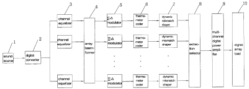
As shown in figure 1, a digital speaker system device having channel
equalization and beam controlling functionalities is provided according to the
present invention, the main body of which comprises a sound source 1, a
digital converter 2, a channel equalizer 3, a beam-former 4, a I-A modulator
5,
a thermometer coder 6, a dynamic mismatch shaper 7, a extraction selector 8,
a multi-channel digital power amplifier 9 and a digital array load 10 and the
like.
Wherein the sound source 1 can use the sound source files in MP3 format
stored in the hard discs of PCs and output in digital format via USB ports,
and
can use the sound source files stored in MP3 players and output in analog
format, and can also use the test signals in audio-frequency range generated
by signal source and output in analog format as well as.
18
CA 02853294 2014-04-24
The digital converter 2 is electrically coupled to the output end of the sound
source 1, which contains two input interfaces of digital input format and
analog
input format. For the digital input format, by utilizing a USB interface chip
typed
PCM2706 of Ti Company, the files in MP3 format stored in PCs can be read
real-time into FPGA chips typed Cyclone III EP3C80F484C8 through I2S
interface protocol via USB port, with a bit-width of 16 and a sampling rate of
44.1 KHz. For the analog input format, by utilizing a analog-to-digital
conversion chip typed AD1877 of Analog Devices Company, the analog sound
source signals can be converted into PCM coded signals with a bit-width of 16
and a sampling rate of 44.1 KHz, and can also be read real-time into FPGA
chips through I2S interface protocol.
The channel equalizer 3 is electrically coupled to output end of the digital
converter 2, which calculates the parameters of inverse filter of each channel
by measuring. The magnitude spectrum graphs of inverse filters of channels 1
to 8 are shown in figure 5, the PCM signals after equalization with a bit-
width of
16 and a sampling rate of 44.1 KHz are obtained by performing equalization
processing on the channels in terms of the parameters of inverse filters.
The beam-former 4 is electrically to output end of the channel equalizer 3,
which calculates weighted vectors of the 8-element array according to the
desired beam pattern, then loads the calculated weighted vectors to the
transmission signals of each array channel by multiplier unit, i.e., the PCM
signals after equalization with a bit-width of 16 and a sampling rate of 44.1
KHz,
thereby forming the multi-channel PCM signals with orientation weighted
regulation.
The E-A modulator 5 is electrically coupled to the output end of the
beam-former 4, the PCM coded signals of 44.1 KHz, 16-bit are processed with
a 3-level up-sampling interpolation inside the FPGA chip, wherein the first
level
interpolation factor is 4, and the sampling rate is 176.4 KHz, the second
level
interpolation factor is 4 and the sampling rate is 705.6 KHz, while the third
level
interpolation factor is 2 and the sampling rate further increases to 1411.2
KHz.
19
CA 02853294 2014-04-24
After the 32 times interpolating, the original signals of 44.1 KHz, 16-bit are
converted into the over-sampling PCM coded signals of 1.4112 MHz, 16-bit.
Then the over-sampling PCM coded signals of 1.4112 MHz, 16-bit are
converted into PCMb coded signals of 1.4112 MHz, 3-bit by 3-bit I-A
modulation. As shown in figure 6, in this embodiment, the I-A modulator 5 is
provided with a fifth-order CIFB (Cascaded Integrators with Distributed
Feedback) topology construction. The coefficient of the I-A modulator 5 is
shown in table 1. In order to save hardware resource and reduce the
realization cost, the constant multiplication operation is generally
substituted
by the shift addition operation inside the FPGA chip, and the parameters of
the
I-A modulator are depicted in CSD code.
The thermometer coder 6 is electrically coupled to the output end of the I-A
modulator 5, which converts the I-A modulation signals of 1.4112 MHz, 3-bit
into unary codes of 1.4112 MHz, 8-bit by thermometer coding. As shown in
figure 7, when the PCM code of 3-bit is "001" and the converted thermometer
code thereof is "00000001", the code is used for controlling one element being
on status and the other 7 elements being off status of the transducer array.
When the PCM code of 3-bit is "100" and the converted thermometer code
thereof is "00001111", the code is used for controlling four elements being on
status and the other 4 elements being off status of the transducer array.
While
when the PCM code of 3-bit is "111" and the converted thermometer code
thereof is "01111111", the code is used for controlling seven elements being
on
status and only the residual one element being off status of the transducer
array.
The dynamic mismatch shaper 7 is electrically coupled to the output end of the
thermometer coder 6, which is used for eliminating the nonlinear harmonic
distortion components arisen from the frequency difference between array
elements. The dynamic mismatch shaper 7 reorders the 8-bit thermometer
codes according to the optimum criteria of least nonlinear harmonic distortion
components, thereby determining the code assigning way to the 8 transducers.
CA 02853294 2014-04-24
As shown in figure 7, when the thermometer code is"00001111", after the
reordering of the dynamic mismatch shaper 7, it will be determined that the
transducer elements 1, 4, 5, 7 are allocated code "1" and the transducer
elements 2, 3, 6, 8 are allocated code "0", and thus the transducer elements
1,
4, 5, 7 will be on and the transducer elements 2, 3, 6, 8 will be off by this
assigning way. Performing the on/off control of the transducer array according
to the code allocation way will make the synthesized signals of the sound
fields
emitted by array contain the least harmonic distortion components. In this
embodiment, the dynamic mismatch shaper utilizes VFMS (Vector-Feedback
mismatch shaping) algorithm, the process of signal processing is shown in
figure 8, wherein the heavy line represents the N dimension vector and the
thin
line represents scalar, the input signal V is N dimension code vector
processed
by the Z-A modulator and the thermometer coder, in which the code vector
contains v "1" status and N -v "0" status, and the output signal is N
dimension vector processed by the mismatch shaper, the order of the "1"
status and the "0" status of the output vector is adjusted by the mismatch
shaping processing, but the numbers of the "1" status and the "0" status still
remain , moreover, each element of the vectors controls the on/off action of
the
corresponding channel of array element in array according to the status
thereof. Via certain selection scheme, the unit selection module ensures the
error arisen from frequency difference has better shaping effect on frequency
spectrum , wherein ¨ min() module represents selecting the element of
minimum number value from the N dimension vectors and negating it, the
scalar element obtained by ¨ min() module operation is u , and
mtf represents the mismatch shaping function, the general form of which is
¨ z-1)"1 and M is the order, the order of the mismatch shaper utilized in this
embodiment is 2-order. According to the flow chart of signal processing of
21
CA 02853294 2014-04-24
figure 8, the expression of the output vector after mismatch shaping
processing is obtained as follows:
sv = 1 = = = 1101 + mtAse),
Wherein se=sv¨y. Provided that the N dimension vector ed represents the
unconformity error between array units, and the sum of all elements of ed is
0,
then the expression of the output sound signals of array obtained through the
superposition of the output sound field of each array in the any spatial
location
by the speaker array is as follows:
X = SV X ed
= [u[1 1 = = = 11.N + mtf (se)ix ed
=u[1 1 = = = 1IN x ed + mtf (se) x ed
= u x 0+ mtf (se) x ed
It can be seen from the expression of the output sound signals of array that
the
shaping function mtf can shape the array error ed , and the better shaping
effect on the array error ed can be achieved when the better mismatch shaping
function is selected. Within the FPGA chip, the harmonic components existing
in the original Z-L, coded signals are pushed to high frequency section out of
band, thereby improving the sound quality of the sound source signals in band.
The extraction selector 8 is electrically coupled to the output end of the
dynamic mismatch shaper 7, which is used for extracting the digit from the
shaping vectors of each channel to send to the post-stage circuit of the power
amplifier and digital load. As shown in figure 9, each channel generates one
unary code vector of 8-element by mismatch shaping processing, the
extraction selector 7 will extract unary code signal of a corresponding digit
for
each channel as the input signal of the post-stage digital power amplifier,
according to the rule of the ith channel extracting the ith digit of the
shaping
vector.
22
CA 02853294 2014-04-24
The multi-channel digital power amplifier 9 is electrically coupled to the
output
end of the extraction selector 8. In this embodiment, the digital power
amplifier
chip is a digital power amplifier chip typed TAS5121 from Ti Company, the
response time of the chip is 100 ns order of magnitude, and the distortionless
response of the unary code flow signal of 1.4112 MHz can be achieved. The
differential input format is used in the input end of the power amplifier, one
path of the output data from the dynamic mismatch shaper is output directly
and the other path is output inversely, thus forming two paths of differential
signals and sending them to the differential output end of the TAS5121 chip.
While the differential output format is used in the output end of the power
amplifier, the two paths of differential signals are applied to the positive
and
negative lead wires of the array element channel of single transducer.
The digital array load 10 is electrically coupled to the output end of the
multi-channel digital power amplifier 9. In this embodiment, the digital load
unit
is the speaker unit of full frequency band typed B2S produced by HuiWei
Company, the frequency band range of the unit is 270 Hz-20 KHz, the
sensitivity (2.83V/1m) is 79 dB, the maximum power is 2 W, and the rated
impedance is 8 ohm. As shown in figure 10, the digital load 8 is a speaker
array of 8-element, the array comprises 8 said speaker units arranging
according to a linear array way, the array elements are at 4 cm interval, and
each speaker unit corresponds to a digital channel.
In the free space, provided that the arrangement of the speaker array and the
microphone unit is shown in figure 11, according to the simulation experiment
method, provided that the swept signals of 100 Hz-20 KHz are input into the
digital speaker system device, the frequency response characteristic of the
system is observed at the location point of one meter away from the axis of
the
speaker array. Figure 12 shows the magnitude spectrum comparative graphs
of the system frequency response at the location point of one meter away from
the axis before and after applying the equalizer, the magnitude spectrum of
the
system frequency response has an obvious downtrend in the frequency range
23
CA 02853294 2014-04-24
of 2 KHz-20 KHz before applying equalizer, and the magnitude spectrum of
the system frequency response decreases from 65 dB to 45 dB, thus there is
20 dB magnitude difference here. After applying equalizer, the magnitude
spectrum of the system frequency response still maintains 57 dB
approximately in the frequency range of 2 KHz-20 KHz and presents flat
spectrum characteristic, thereby ensuring the actual restoration of the
synthetic signals of the system. It can be seen from the result of
equalization
that the equalizer response information of each channel can be succeeded
effectively by utilizing the multi-channel bit information synthesis way of
extraction selection, thereby ensuring the frequency response flatness of each
channel.
The digital speaker array system based on channel equalization can eliminate
effectively the frequency response fluctuation in audio band of each channel
and correct the frequency response difference between channels, and thus
ensures the system has the quite flat time-domain frequency characteristics,
thereby ensuring the spectrum of the spatial synthetic signals of all channels
can restore the real spectrum of the original sound source signals and the
digital replay system can reproduce the sound field effect of the original
sound
source actually. Additionally, eliminating the frequency response fluctuation
in
audio band of each channel can ensure various self-adaptive spatial domain
array beam-forming algorithms have the higher convergence rate and the
better robustness.
In the free space, in terms of the speaker array arrangement way as shown in
figure 11, the simulation experiment of array beam controlling can be carried
out according to the three predetermined beam main lobe directions of -60
degree, 0 degree and +30 degree, all the array lode width of the three
circumstances is set as 20 degree. The spatial pattern of the array in the
three
predetermined directions is shown in figure 13, it can be seen from these
graphs that the beam main lobe of the array points at the predetermined
24
CA 02853294 2016-05-13
direction, the beam width reaches the desired demand, and the magnitude
difference value between the main lobe and side lobe reaches 15 dB. It is
known from the result of these array beam controlling that, utilizing the
multi-
channel information synthesis way of extraction selecting can succeed
effectively the magnitude and phase adjustment information loaded on each
channel by beam-former, thereby achieving the beam directionality control of
array. This digital array beam-forming method based on extraction selecting
can enhance the spatial directional ability of the digital array in
complicated
environment, and provide a reliable realizing way for the effect generation of
the special sound field of the digital array, such as 3D stereo sound field,
virtual
surround sound field and directivity sound field etc.
It should be stated that the above embodiments are simply intended to
illustrate
the technical scheme of the invention, instead of limitation. Although the
invention is described in detail with reference to the embodiment, it should
be
appreciated by those skilled in the art that any variations or equal
replacements
of the technical scheme of the invention are covered within the scope of the
invention, and that the scope of the claims should not be limited by the
preferred embodiments set forth in the examples, but should be given the
broadest interpretation consistent with the description as a whole.