Language selection

Search

Patent 2853427 Summary

Third-party information liability

Some of the information on this Web page has been provided by external sources. The Government of Canada is not responsible for the accuracy, reliability or currency of the information supplied by external sources. Users wishing to rely upon this information should consult directly with the source of the information. Content provided by external sources is not subject to official languages, privacy and accessibility requirements.

Claims and Abstract availability

Any discrepancies in the text and image of the Claims and Abstract are due to differing posting times. Text of the Claims and Abstract are posted:

  • At the time the application is open to public inspection;
  • At the time of issue of the patent (grant).
(12) Patent Application: (11) CA 2853427
(54) English Title: RESERVOIR ASSEMBLY WITH BREATHER VENT
(54) French Title: ENSEMBLE DE RESERVOIR A RENIFLARD
Status: Dead
Bibliographic Data
(51) International Patent Classification (IPC):
  • F15B 21/00 (2006.01)
(72) Inventors :
  • WIENS, SCOTT R. (United States of America)
  • BILL, RANDALL K. (United States of America)
  • LEMIRE, JARROD A. (United States of America)
(73) Owners :
  • DEERE & COMPANY (United States of America)
(71) Applicants :
  • DEERE & COMPANY (United States of America)
(74) Agent: BORDEN LADNER GERVAIS LLP
(74) Associate agent:
(45) Issued:
(22) Filed Date: 2014-06-04
(41) Open to Public Inspection: 2014-12-17
Availability of licence: N/A
(25) Language of filing: English

Patent Cooperation Treaty (PCT): No

(30) Application Priority Data:
Application No. Country/Territory Date
13/919,338 United States of America 2013-06-17

Abstracts

English Abstract


A vehicle hydraulic oil reservoir assembly includes a main reservoir and an
auxiliary reservoir. The main reservoir has a lower portion and an upper
portion. The
auxiliary reservoir has a lower portion and an upper portion. The auxiliary
reservoir
has a port formed in the upper portion thereof. The lower portion of the
auxiliary
reservoir is communicated with the lower portion of the main reservoir. A
breather
vent is in communication with atmosphere. A vent pipe communicates the port
with
the breather vent.


Claims

Note: Claims are shown in the official language in which they were submitted.


CLAIMS:

1. A reservoir assembly comprising:
a main reservoir having a lower portion and an upper portion, the main
reservoir having a main port formed in the upper portion thereof;
a main vent conduit having a first end which communicates the main port, the
main vent conduit extending away from the first end, the main vent conduit
having a
first resistance to air flow therethrough;
an auxiliary reservoir having a lower portion and an upper portion, the
auxiliary
reservoir having an auxiliary port formed in the upper portion thereof, the
lower
portion of the auxiliary reservoir being communicated with the lower portion
of the
main reservoir;
a breather vent which is in communication with atmosphere; and
a vent pipe which communicates the auxiliary port with the breather vent, the
vent pipe having a second resistance to air flow therethrough, the first
resistance
being greater than the second resistance so that fluid will release faster
from the
auxiliary reservoir than from the main reservoir.
2. The reservoir assembly of claim 1, wherein:
a passage connects the lower portion of the auxiliary reservoir to the lower
portion of the main reservoir
3. The reservoir assembly of claim 1, wherein:
the auxiliary reservoir encloses a chamber having a first upper chamber
communicated with a second upper chamber through a lower chamber;
a first port is communicated with an upper portion of the first upper chamber;

a second port is communicated with an upper portion of the second upper
chamber; and
a vent pipe communicates the first port with the second port.
4. The reservoir assembly of claim 1, wherein:
the main reservoir is enclosed by a differential housing.
5. A vehicle hydraulic oil reservoir assembly, comprising:


a main reservoir having a main port formed in an upper portion thereof;
a main vent conduit having a first end which communicates the main port, the
main vent conduit extending away from the first end, the main vent conduit
having a
first resistance to air flow therethrough;
an auxiliary reservoir having a lower portion and an upper portion, the
auxiliary
reservoir having an auxiliary port formed in the upper portion thereof, the
lower
portion of the auxiliary reservoir being communicated with a lower portion of
the main
reservoir;
a breather vent which is in communication with atmosphere; and
a vent pipe which communicates the auxiliary port with the breather vent, the
vent conduit being longer than the vent pipe so that resistance to air flow
through the
vent conduit is greater than resistance to air flow through the vent pipe, and
so that
oil will release faster from the auxiliary reservoir than from the main
reservoir.
6. The hydraulic oil reservoir assembly of claim 5, wherein:
the main reservoir is enclosed by a differential housing.
7. The hydraulic oil reservoir assembly of claim 5, further comprising:
a further auxiliary reservoir having a lower portion and an upper portion, the

further auxiliary reservoir having a further port formed in the upper portion
thereof,
the lower portion of the further auxiliary reservoir being communicated with
the lower
portion of the main reservoir;
a further breather vent which is in communication with atmosphere; and
a further vent pipe which communicates the further port with the further
breather vent.
8. A vehicle hydraulic oil reservoir assembly, comprising:
a differential housing enclosing a main reservoir, the main reservoir having a

main port formed in an upper portion thereof;
a main vent conduit having a first end which is communicated with the main
port, the main vent conduit extending away from the first end, the main vent
conduit
having a first resistance to air flow therethrough;
an auxiliary reservoir, the auxiliary reservoir having an auxiliary port
formed in

6


an upper portion thereof;
a passage communicating the auxiliary reservoir with the main reservoir;
a breather vent which is in communication with atmosphere; and
a vent pipe which communicates the auxiliary port with the breather vent, the
vent conduit being longer than the vent pipe so that resistance to air flow
through the
vent conduit is greater than resistance to air flow through the vent pipe, and
so that
oil will release faster from the auxiliary reservoir than from the main
reservoir.
9. A vehicle hydraulic oil reservoir assembly, comprising:
a differential housing enclosing a main reservoir, the main reservoir having a

lower portion and an upper portion;
a first auxiliary reservoir having a lower portion and an upper portion, the
first
auxiliary reservoir having a first port formed in the upper portion thereof,
the lower
portion of the first auxiliary reservoir being communicated with the lower
portion of
the main reservoir;
a further auxiliary reservoir having a lower portion and an upper portion, the

further auxiliary reservoir having a further port formed in the upper portion
thereof,
the lower portion of the further auxiliary reservoir being communicated with
the lower
portion of the main reservoir;
a first breather vent which is in communication with atmosphere;
a first vent pipe which communicates the first port with the breather vent;
a further breather vent which is in communication with atmosphere; and
a further vent pipe which communicates the further port with the further
breather vent.

7
Description

Note: Descriptions are shown in the official language in which they were submitted.


CA 02853427 2014-06-04
RESERVOIR ASSEMBLY WITH BREATHER VENT
Field
The present disclosure relates to a hydraulic oil reservoir assembly for a
vehicle.
Backoround
Utility vehicles, such as tractors, include a main hydraulic oil reservoir and
at
least one auxiliary reservoir. On current production tractors, the auxiliary
reservoirs
have air vent lines that communicate back to the upper end of the main
reservoir.
With such an arrangement, when a towed implement, such as a wagon with a dump
cylinder is coupled to the tractor hydraulic system, oil will be drawn out of
the main
reservoir. In such situations, the main reservoir oil level will always be
below the
auxiliary reservoir oil level, and the main reservoir can be emptied while
unused oil
remains in the auxiliary reservoir. If the main reservoir oil level gets too
low, no more
oil can be supplied to the dump cylinder, and extra, unused oil will remain in
the
auxiliary reservoir.
Previously, EH valves and extra pumps have been used to insure the
maximum amount of oil is used from the auxiliary reservoir. However, such
components are costly and require control software and wiring harness
integration
and place an extra hydraulic load on the tractor.
Summary
According to an aspect of the present disclosure, a vehicle hydraulic oil
reservoir assembly includes a main reservoir and a pair of auxiliary
reservoirs. The
main reservoir has a lower portion and an upper portion. The first auxiliary
reservoir
has a lower portion and an upper portion. The first auxiliary reservoir has a
first port
formed in the upper portion thereof. The lower portion of the first auxiliary
reservoir is
communicated with the lower portion of the main reservoir. A further auxiliary

reservoir has a lower portion and an upper portion. The further auxiliary
reservoir
has a further port formed in the upper portion thereof. The lower portion of
the further
auxiliary reservoir is also communicated with the lower portion of the main
reservoir.
1

CA 02853427 2014-06-04
A first breather vent is in communication with atmosphere. A first vent pipe
communicates the first port with the breather vent. A further breather vent is
also in
communication with atmosphere, and a further vent pipe communicates the
further
port with the further breather vent. The breather vents cause the auxiliary
reservoirs
to empty before the main reservoir, so that all of the available oil can be
utilized.
Brief Description of the Drawings
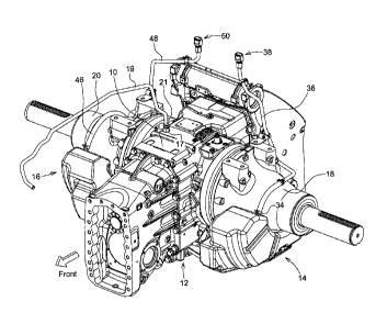
Fig. 1 is a perspective view of an oil reservoir assembly embodying the
invention;
Fig. 2 is a left side view of the oil reservoir assembly of Fig. 1; and
Fig. 3 is a view taken along lines 3-3 of Fig. 2; and
Fig. 4 is a right side view of the oil reservoir assembly of Fig. 1;
Fig. 5 is a sectional view of the breather vents of Figs. 1 and 2; and
Fig. 6 is a view taken along lines 6-6 of Fig. 3.
Detailed Description of the Drawings
Referring to Figs 1 and 2, a vehicle differential case 10 encloses a main
hydraulic oil reservoir 12. Left and right auxiliary oil reservoirs 14 and 16
are
mounted outboard of the differential case 10 and below corresponding left and
right
inner axle housings 18 and 20.
As best seen in Figs. 1 and 3, a main port 17 is formed in the upper part of
the
main reservoir 12. A main vent conduit 19 has a first end 21 which
communicates
the main port 17, and the main vent conduit 19 extends away from the first end
21 to
a second end 23. The second end 23 may be connected to another vehicle
component, such as the transmission housing (not shown), which has it's own
breather vent (not shown). The main vent conduit 19 has a first resistance to
air flow
therethrough.
As best seen in Fig. 3, the lower portion of left auxiliary reservoir 14 is
communicated to the lower portion 24 of the main reservoir 12 by a pipe 26 and
a
passage 28 which extends through the lower left side of the housing 30 of the
2

CA 02853427 2014-06-04
differential case 10. The lower portion of right auxiliary reservoir 16 is
communicated
to the lower portion 24 of the main reservoir 12 by a pipe 32 and a passage
(not
shown) which extends through the lower right side of housing 30 of the
differential
case 10.
Referring to Figs. 1 and 2, an opening or port 34 is formed in an upper
portion
of left auxiliary reservoir 14. A left vent pipe 36 communicates port 34 to a
breather
vent 38 which is communicated with the atmosphere.
As best seen in Figs. 4 and 6, the right auxiliary reservoir 16 encloses a
chamber having a first upper chamber 15 communicated with a second upper
chamber 17 through a lower chamber 19. Port 40 is formed in upper portions of
chamber 15. Ports 42 and 44 are formed in upper portions of chamber 17. A vent

pipe 46 communicates port 40 to port 42. A right vent pipe 48 communicates
port 44
to a breather vent 50 which is communicated with the atmosphere.
Referring now to Fig. 5, the breather vents 38 and 50 have caps 52 which
have ports 54 which communicate the interior of vent pipes 36 and 48 to the
atmosphere. The breather vents 38 and 50 allow the main reservoir 10 to pull
all of
the oil out of the auxiliary reservoirs 14 and 16 before the main reservoir 10
is
emptied. This makes a greater amount of oil available for take-out purposes,
such as
transferring to a remote cylinder, without changing the size or shape of the
main and
auxiliary reservoirs. Using the extra breather vents add minimal cost and
complexity
while making available the entire oil volume of the auxiliary reservoirs.
Vent conduit 19 is longer than vent pipe 36 or of vent pipe 48, and therefore
has a resistance to air flow which is greater than the air flow resistance of
vent pipe
36 or of vent pipe 48. As a result, the auxiliary reservoirs 14 and 16 will
release fluid
faster than will the main reservoir 12. The air flow resistance of the vent
conduit 19
may be made greater than the air flow resistance of the vent pipe 36 or of
vent pipe
48 by making the vent conduit 19 longer than vent pipe 36 or vent pipe 48, or
by
making the vent conduit 19 with a smaller diameter than that of vent pipe 36
or of
vent pipe 48.
While the disclosure has been illustrated and described in detail in the
3

CA 02853427 2014-06-04
drawings and foregoing description, such illustration and description is to be

considered as exemplary and not restrictive in character, it being understood
that
illustrative embodiments have been shown and described and that all changes
and
modifications that come within the spirit of the disclosure are desired to be
protected.
It will be noted that alternative embodiments of the present disclosure may
not
include all of the features described yet still benefit from at least some of
the
advantages of such features. Those of ordinary skill in the art may readily
devise
their own implementations that incorporate one or more of the features of the
present
disclosure and fall within the spirit and scope of the present invention as
defined by
the appended claims.
4

Representative Drawing
A single figure which represents the drawing illustrating the invention.
Administrative Status

For a clearer understanding of the status of the application/patent presented on this page, the site Disclaimer , as well as the definitions for Patent , Administrative Status , Maintenance Fee  and Payment History  should be consulted.

Administrative Status

Title Date
Forecasted Issue Date Unavailable
(22) Filed 2014-06-04
(41) Open to Public Inspection 2014-12-17
Dead Application 2018-06-05

Abandonment History

Abandonment Date Reason Reinstatement Date
2017-06-05 FAILURE TO PAY APPLICATION MAINTENANCE FEE

Payment History

Fee Type Anniversary Year Due Date Amount Paid Paid Date
Application Fee $400.00 2014-06-04
Maintenance Fee - Application - New Act 2 2016-06-06 $100.00 2016-05-18
Owners on Record

Note: Records showing the ownership history in alphabetical order.

Current Owners on Record
DEERE & COMPANY
Past Owners on Record
None
Past Owners that do not appear in the "Owners on Record" listing will appear in other documentation within the application.
Documents

To view selected files, please enter reCAPTCHA code :


To view images, click a link in the Document Description column. To download the documents, select one or more checkboxes in the first column and then click the "Download Selected in PDF format (Zip Archive)" or the "Download Selected as Single PDF" button.

List of published and non-published patent-specific documents on the CPD .

If you have any difficulty accessing content, you can call the Client Service Centre at 1-866-997-1936 or send them an e-mail at CIPO Client Service Centre.


Document
Description 
Date
(yyyy-mm-dd) 
Number of pages   Size of Image (KB) 
Abstract 2014-06-04 1 13
Description 2014-06-04 4 159
Claims 2014-06-04 3 122
Drawings 2014-06-04 6 177
Representative Drawing 2014-11-19 1 29
Cover Page 2014-12-23 1 60
Assignment 2014-06-04 4 87