Note: Descriptions are shown in the official language in which they were submitted.
CA 02853429 2014-06-03
CFP-5958CA
SAFETY FEEDER USABLE WITH DIFFERENT WOODWORKING MACHINES
2
3 Background of the Invention
4 The
present invention relates to a feeder and, particularly to a feeder
with two pressing rollers set apart and usable with different wood working
6 machines.
7 There
are various types of woodworking machines nowadays.
8 Planning
and sawing are basic woodworking operations. Upon a planning
9
operation, a wood workpiece can be planed to include a groove having a
planer or a special shape. Upon a sawing operation, the wood workpiece can
1 i. be sawed to include a special shape. There are specific woodworking
12 machines
for different characteristics of planning operations. In =addition, a
13 feeder
would be fit to a woodworking machine to feed the wood workpiece
14 into the
woodworking machine, but, it is noted that ways of feeding the wood
= 15 workpiece are different with respect to different processing methods
of the
16 wood
workpiece, because cutters have specific shapes and specific feeders
17 have to
be used in order to feed the wood workpiece stably and safely.
18 However,
a lot of money is needed for designing different feeders for
= 19 different woodworking machines.
Fig. 14 shows a feeder fit to a woodworking machine. The feeder is
21 disposed
above a platform of a woodworking machine. The feeder includes a
22 row of
pressing rollers. There are three pressing rollers. When the feeder is
23 feeding
a wood workpiece, the feeder includes the pressing rollers disposed
CA 02853429 2014-06-03
CFP-5958CA
1 on one
side of a cutter of the woodworking machine, pressing the wood
2 workpiece
against the platform, and conveying the wood workpiece, however,
3 this
conventional feeder is only able to press against a half of the wood
4 workpiece
and is unable to press against the other half. Therefore, the half of
the wood workpiece that is not pressed by the feeder rollers is not pushed by
6 the feeder
rollers and needs an exterior force to overcome frictions associated
7 with the
other half of the wood workpiece, the platform, and a fence of the
8
woodworking machine it abuts against in order to move simultaneously with
9 the other
half of the wood workpiece. Generally, a user manually exerts a
force to push the wood workpieces. However, it could be hazardous. It is
11 noted that
if the halves of the wood workpiece are not moved simultaneously,
12 the cutter
can not stably cut the wood workpiece and produce an accurate cut.
13
14 Summary of the Invention
According to the present invention, a safety feeder usable with
16 different woodworking machines includes a fixing frame releasably
17 mountable
on a woodworking machine. A device connects to the fixing
18 frame. The
fixing frame cranes the device. The device includes a drive
19 device, a
transmission system, and at least one first and second pressing
rollers. The drive device engages with and is able to drive the at least one
21 first and
second pressing rollers through the transmission system. The
22
transmission system includes an axle engaging with the at least one first and
23 second
pressing rollers. The at least one first and second pressing rollers are
2
CA 02853429 2015-12-03
75351-37
disposed separately in an axial direction with a predetermined gap on the
axle.
According to another aspect of the invention, there is provided a safety
feeder
usable with different wood working machines comprising: a fixing frame
releasably
mountable on a wood working machine; and a device, connecting to the fixing
frame, with
fixing frame craning the device, and including a drive device, a transmission
system, and at
least one first and second pressing rollers, with the drive device engaging
with and being able
to drive the at least one first and second pressing rollers through the
transmission system, with
the transmission system including an axle engaging with the at least one first
and second
pressing rollers, and with the at least one first and second pressing rollers
disposed separately
in an axial direction with a predetermined gap on the driven axle; wherein
each of the at least
one first and second pressing roller has a hub with a first side forming a
recess and a second
side opposite to the first side forming a protrusion, wherein the at least one
first pressing roller
includes a plurality of first pressing rollers engaging with the axle, wherein
adjacent two of
the plurality of first pressing rollers have two arrangements, with the
adjacent two of the
1 5 plurality of first pressing rollers overlapping together without a gap
and having
circumferential edges combined and adjacent to each other in a first
arrangement, and with the
adjacent two of the plurality of first pressing rollers overlapping together
with a gap and
having the circumferential edges separated with the gap in a second
arrangement.
Brief Description of the Drawings
Fig. 1 is a perspective view of a safety feeder usable with different wood
working machines in accordance with the present invention.
Fig. 2 is a partial, exploded perspective view of the safety feeder of the
present
invention.
Fig. 3 is a partial, cross-sectional view of the safety feeder of the present
invention.
Fig. 4 is a partial, top view of the safety feeder of the present invention,
with
the feeder set to a first orientation.
3
CA 02853429 2015-12-03
=
75351-37
Fig. 5 is similar to Fig. 4, except that the feeder is set to a second
orientation
different from the first orientation.
Fig. 6 is a partial, cross-sectional view of a transmission and rollers of the
feeder of the present invention.
Fig. 7 is an exploded perspective view showing the rollers in an arrangement
different from that of Fig. 6, with two rollers separating from each other and
including a
spacer disposed therebetween.
Fig. 8 is a partial, cross-sectional view of Fig. 7.
Fig. 9 is an exploded perspective view showing the roller in another
arrangement different from that of Fig. 7, with two rollers separating from
each other.
Fig. 10 is a partial, cross-sectional view of Fig. 9.
3a
CA 02853429 2014-06-03
CFP-5958CA
1 Fig. 11 is
a perspective view of the feeder of the present invention and
2 a circular
saw machine, with the feeder feeding a wood workpiece to be
3 processed by the circular saw machine.
4 Fig. 12 is
a perspective view of the feeder of the present invention and
a band saw machine, with the feeder feeding a wood workpiece to be
6 processed by the band saw machine.
7 Fig. 13 is
a perspective view of the feeder of the present invention and
8 a wood
shaper, with the feeder feeding a wood workpiece to be processed by
9 the wood shaper.
Fig. 14 is a perspective view of a conventional feeder and a wood
11 working
machine, with the feeder feeding a wood workpiece to be processed
12 by the wood working machine.
13
14 Detailed Description of the Invention
Figs. 1 through 13 show a safety feeder usable with different
16
woodworking machines in accordance with the present invention. The feeder
17 includes a
fixing frame 10 releasably mountable on a woodworking machine.
18 A device 20 connects to the fixing frame 10.
19 The fixing
frame 10 cranes the device 20. The fixing frame 10
includes a plurality of beams 11 telescopically connected with each other.
21 The fixing
frame 11 includes at least one of the plurality of beams 11 securing
22 to the
woodworking machine. In the embodiment, the at least one of the
23 plurality of beams 11 that secures to the woodworking machine are
24 suspended
by at least one bracket 13. The at least one bracket 13 is fixable to
4
CA 02853429 2014-06-03
CFP-5958CA
1 the woodworking machine. The fixing frame 10 includes at least two of the
2 plurality of beams 11 telescopically connected with and movable relative
to
3 each other in a first direction that affects a vertical position of the
device 20
4 with respect to the woodworking machine. The fixing frame 10 includes at
least two of the plurality of beams 11 telescopically connected with and
6 movable relative to each other in a second direction that affects a
horizontal
7 position of the device 20 with respect to the woodworking machine. The
8 device 20 is pivotally positionable at a fixed pivoting position with
respect to
9 the fixing frame 10. The fixing frame 10 and device 20 include a pivot
joint
12 connecting therewith. The pivot joint 12 includes a first pivot joint 121
11 pivotally engaging with the fixing frame 10 and a second pivot joint 122
12 pivotally engaging with the device 20 and includes the first and second
pivot
13 joints 121 and 122 pivotally engaging with each other. A first pivot 127
14 engages with the first and second pivot joints 121 and 122. A second
pivot
128 engages with the second pivot joint 122 and the device 20. The first
16 pivot joint 121 pivots with respect to the fixing frame 10 in a first
orientation.
17 The second pivot joint 122 pivots with respect to the first pivot joint
121 in
18 the first orientation. The device 20 pivots with respect to the second
pivot
19 joint 122 in a second orientation. The pivot joint 12 includes first and
second
slots 123 and 124, a first locking member 125 engaging with the first and
21 second pivot joint 121 and 122 and inserting through the first slot 123,
and a
22 second locking member 126 engaging with the second pivot joint 122 and
the
23 device 20 and inserting through the second slot 124. The first and
second
24 slots 123 and 124 define two arcuate slots. The first locking member 125
has
5
CA 02853429 2014-06-03
CFP-5958CA
1 a lock position in which the first and second pivot joints 121 and 122
are at a
2 fixed relative pivoting position and an unlock position in which the
first and
3 second pivot joints 121 and 122 are pivotal relative to each other. The
second
4 locking member 126 has a lock position in which the second pivot joint
122
and the device 20 are at a fixed relative position and an unlock position in
6 which the second pivot joint 122 and the device 20 are pivotal relative
to each
7 other. The pivot joint 12 has two scales, with one scale indicating a
pivoting
8 position of the second pivot joint 122 with respect to the first pivot
joint 121,
9 and with the other scale indicating a pivoting position of the device 20
with
respect to the second pivot joint 122.
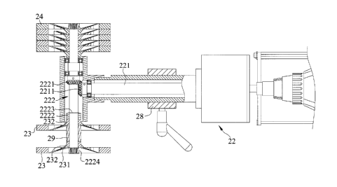
11 The device 20 includes a drive device 21, a transmission system 22,
12 and at least one first and second pressing rollers 23 and 24. The drive
device
13 21 engages with and is able to drive the at least one first and second
pressing
14 rollers 23 and 24 through the transmission system 22. The drive device
21
can be a power tool as shown in the drawings, a pneumatic tool, or a motor,
16 but not limiting. The transmission system 22 includes a shaft 221 and an
axle
17 222 engaging with the shaft 221. The shaft 221 interconnects the drive
18 device 21 and the axle 222. The drive device 21 drives the shaft 221.
The
19 drive device 21 turns the shaft 221. The shaft 221 drives the axle 222.
The
shaft 221 turns the axle 222. The shaft and the axle 221 and 222 are arranged
21 perpendicularly to each other. The shaft 221 includes a first bevel gear
2211
22 and the second axle 222 includes a second bevel gear 2221 engaging with
the
23 first bevel gear 2211. The axle 222 engages with the at least one first
and
24 second pressing rollers 23 and 24. One of the at least one first and
second
6
CA 02853429 2014-06-03
CFP-5958CA
1 pressing rollers 23 and 24 and the second bevel gear 2221 include a
spacing
2 member 2222 and a first restraining members 2223 disposed therebetween.
3 The axle 222 engages with the spacing member 2222 and the first
restraining
4 member 2223. The spacing member 2222 is disposed between the first
restraining member 2223 and one of the at least one first and second pressing
6 rollers 23 and 24. A second restraining member 2224 engages with the axle
7 222. The first and second restraining member 2223 and 2224 limit axial
8 movement of the spacing member 2222 and one of the at least one first and
9 second pressing rollers 23 and 24 on the axle 222. The axle 222 drives
the at
least one first and second pressing rollers 23 and 24. The axle 222 turns the
at
11 least one first and second pressing rollers 23 and 24. The at least one
first and
12 second pressing rollers 23 and 24 are disposed on two different ends of
the
13 axle 222. The at least one first and second pressing rollers 23 and 24
are
14 disposed separately in an axial direction with a predetermined gap on
the axle
222. The at least one first and second pressing rollers 23 and 24 are of the
16 same configuration. The second bevel gear 2221 is in between the first
and
17 second pressing rollers 23 and 24. A sleeve 25 receives the shaft 221
and the
18 axle 222. The sleeve includes a first sleeve section delimiting a first
area
19 receiving the shaft 221 and a second sleeve section delimiting a second
area
receiving the axle 222 respectively. The first and second areas are connected
21 and in communication with each other. The sleeve 25 is T shaped, with
the
22 first and second sleeve sections extending perpendicularly to each
other. The
23 first sleeve section extends from an outer circumferential periphery of
the
24 second sleeve section. The device 20 includes a body shell 26 that
frames the
7
CA 02853429 2014-06-03
CFP-5958CA
1 at least one first and second pressing rollers 23 and 24. The body shell
26 and
2 the pivot joint 12 pivotally engage with each other. The body shell 26
3 includes a first body shell 261 and a second body shell 262 engaging with
and
4 disposed under the first body shell 261. The second pivot 128 inserts
through
the first body shell 261 and engages with the second body shell 262. The first
6 and second body shells 261 are made separately, but not limiting. The
body
7 shell 26 includes a groove extending therethrough. The groove includes a
8 first groove 2611 and a second groove 2621. The first and second grooves
9 2611 and 2621 are elongated. The first and second grooves 2611 and 2621
are disposed correspondingly to each other. The first and second grooves
11 2611 and 2621 and the shaft 221 extend in the same axial direction. The
first
12 groove 2611 extends on and through the first body shell 261. The second
13 groove 2621 extends on and through the second body shell 262. A
14 suspension system 27 interconnects the body shell 26 and the axle 222.
The
suspension system 27 includes a strut 271, a biasing member 272, a retainer
16 273, a securing member 274, and at least one gasket 275. The strut 271
has a
17 first end pivotally connecting to the axle 222 and a second end inserting
18 through the groove. The strut 271 extends through the first and second
19 grooves 2611 and 2621. The strut 271 includes the first end fixing to the
sleeve 25. The strut 271 inserts through the biasing member 272. The
21 biasing member 272 is a coil spring. The biasing member 272 is disposed
22 between the body shell 26 and the sleeve 25. The biasing member 272 is
23 disposed between the body shell 26 and the axle 222. The retainer 273
24 connects to the second end of the strut 271 and supported by the body
shell 26.
8
CA 02853429 2014-06-03
CFP-5958CA
1 The retainer 273 is slidabble on the body shell 26. The retainer 273
slides on
2 the body shell 26 when the strut 271 pivots. The strut 271 inserts
through and
3 restrains the at least one gasket 275. The biasing member 272 is disposed
4 between the body shell 26 and the gasket 275. A constrainer 28 constrains
the
transmission system 22 and the suspension system 27. The constrainer 28
6 connects to the transmission system 22 and the body shell 26. The
7 constrainer 28 pivotally engages with the body shell 26. The constrainer
28
8 includes a through hole and the shaft 221 of the transmission system 22
9 inserts through the through hole. A fastener 282 inserts into the
constrainer
28. The constrainer 28 is pivotal about a pivot 281 with respect to the body
11 shell 26. The pivot 281 inserts into the constrainer 28 and is secured
to the
12 body shell 26. In this embodiment, the pivot 281 is secured to the
second
13 body shell 262 of the body shell 26. The constrainer 28 is restricted
from
14 rotating with respect to the shaft 221.
Each of the at least one first and second pressing roller 23 and 24 has
16 a hub with a first side forming a recess 231 and a second side opposite
to the
17 first side forming a protrusion 232. The at least one first pressing
roller 23
18 includes a plurality of first pressing rollers 23 engaging with the axle
222.
19 Adjacent two of the plurality of first pressing rollers 23 have two
arrangements, with the adjacent two of the plurality of first pressing rollers
21 23 overlapping together without a gap and having circumferential edges
22 combined and adjacent to each other in a first arrangement, and with the
23 adjacent two of the plurality of first pressing rollers 23 overlapping
together
24 with a gap and having the circumferential edges separated with the gap
in a
9
CA 02853429 2014-06-03
CFP-5958CA
1 second arrangement. Two adjacent of plurality of first pressing rollers
23 in
2 the first arrangement include one protrusion 232 engaging in one recess
231.
3 The two adjacent of the plurality of first pressing rollers 23 in the
second
4 arrangement include the protrusions facing oppositely and abutting against
each other. The two adjacent of the plurality of first pressing rollers 23 in
the
6 second arrangement include a spacer disposed therebetween or the
7 protrusions facing oppositely. The spacer engages with the axle 222. The
8 two adjacent of the plurality of first pressing rollers 23 in the second
9 arrangement include the protrusions facing in the same direction.
Because the adjacent two of the plurality of the first pressing rollers
11 23 in the second arrangement include the gap therebetween, a cutter of
the
12 woodworking machine can align between the adjacent two of the plurality
of
13 the first pressing rollers 23. Therefore, the cutter can cut the wood
workpiece
14 between the adjacent two of the plurality of the first pressing rollers
23, and
one half of the wood workpiece is pressed and pushed by one of the adjacent
16 two first pressing rollers 23 and the other half of the wood workpiece
is
17 pressed and pushed by the other of the adjacent two first pressing
rollers 23,
18 respectively, as shown in Figs. 11 and 12. The at least one second
pressing
19 roller 24 includes a plurality of second pressing rollers 24 engaging
with the
axle 222. Adjacent two of the plurality of second pressing rollers 24 have
21 two arrangements, with the adjacent two of the plurality of second
pressing
22 rollers 24 overlapping together without a gap and having circumferential
23 edges combined and adjacent to each other in a first arrangement, and
with
24 the adjacent two of the plurality of second pressing rollers 24
overlapping
CA 02853429 2014-06-03
CFP-5958CA
1 together with a gap and having the circumferential edges separated vvith
the
2 gap in a second arrangement.
3 Because the adjacent two of the plurality of the second pressing
4 rollers 24 in the second arrangement include the gap therebetween, a
cutter of
the woodworking machine can align between the adjacent two of the plurality
6 of the second pressing rollers 24. Therefore, the cutter can cut the wood
7 workpiece between the adjacent two of the of the plurality of the second
8 pressing rollers 24, and one half of the wood workpiece is pressed and
pushed
9 by one of the adjacent two second pressing rollers 24 and the other half
of the
wood workpiece is pressed and pushed by the other of the adjacent two
11 second pressing rollers 24, respectively.
12 When using the feeder to feed a wood workpiece to the woodworking
13 machine, the at least one first and second pressing rollers 23 and 24
press the
14 wood workpiece against a platform of the woodworking machine and
conveying the wood workpiece. The at least one first and second pressing
16 rollers 23 and 24 turn in the same direction.
17 Figs 11, 12, and 13 show each woodworking machine has a fence
18 backing and allowing the wood workpiece to be fed accurately, with the
fence
19 defining a planar surface, and with the wood workpiece including a
planar
edge abutting against the planar surface of the fence. The safety feeder can
21 move in a first orientation moving parallel to the planar surface of the
fence,
22 with the at least one first and second pressing rollers 23 and 24 moving
in a
23 path parallel to the planar surface of the fence. Therefore, the wood
24 workpiece being fed by the safety feeder is under a force which parallel
to the
11
CA 02853429 2014-06-03
CFP-5958CA
1 planar surface of the fence. The safety feeder can also move in a second
2 orientation moving unparallel to the planar surface of the fence. The
safety
3 feeder moves unparallel to the planar surface of the fence will cause two
4 force components, with a first force component parallel to the planar
surface
of the fence and a second force component perpendicular to the planar
6 surface of the fence. It is appreciated that the second force component
can
7 help the wood workpiece align with the planar surface of the fence.
8 In view of the forgoing, the safety feeder is usable with different
9 woodworking machines and allows a user to cut a wood workpiece safely and
precisely in that the cutter of the woodworking machine can align between
the adjacent two of the plurality of the first pressing rollers 23 and cut the
12 wood workpiece between the adjacent two of the of the plurality of the
first
13 pressing rollers 23, with one half of the wood workpiece being pressed
and
14 pushed by one of the adjacent two first pressing rollers 23, and with
the other
half of the wood workpiece being pressed and pushed by the other of the
16 adjacent two first pressing rollers 23, respectively. Likewise, the
cutter of the
17 woodworking machine can align between the adjacent two of the plurality
of
18 the second pressing rollers 24 and cut the wood workpiece between the
19 adjacent two of the of the plurality of the second pressing rollers 24,
with one
half of the wood workpiece being pressed and pushed by one of the adjacent
21 two second pressing rollers 24, and with the other half of the wood
workpiece
22 being pressed and pushed by the other of the adjacent two second
pressing
23 rollers 24, respectively. Furthermore, the adjacent two of the plurality
of first
12
CA 02853429 2015-12-03
75351-37
1 pressing rollers 23 includes the gap of a size enough for cutters of
other
2 woodworking machines to be disposed therebetween.
3 The foregoing is merely illustrative of the principles of this
invention
4 and various modifications can be made by those skilled in the art
without
departing from the scope of the invention.
13