Note: Descriptions are shown in the official language in which they were submitted.
HERNIA REPAIR DEVICE AND METHOD
BACKGROUND
Technical Field
[0002] The present disclosure relates to hernia repair devices and, more
particularly,
to surgical mesh prosthetics for use in hernia repair.
Background of Related Art
[0003] Wound closure devices, such as sutures, filaments, and staples, as
well as
other repair devices, such as mesh or patch reinforcements, are frequently
used to
repair tissue defects, e.g., herniated tissue, and other damaged and/or
diseased tissue.
For example, in the case of hernias, a surgical mesh or patch is commonly used
to
reinforce the abdominal wall. The surgical mesh is generally sized to extend
across the
defect and is adapted to flex or bend in order to conform to the abdominal
wall. The
surgical mesh is typically held in place by adhering, suturing or stapling the
mesh to the
surrounding tissue.
[0004] However, difficulties may arise during the course of a hernia
repair procedure,
particularly with regard to securely affixing the mesh to surrounding tissue.
These
difficulties are often attributed to anatomical spatial constrains and/or
reduced, or
-1-
CA 2853562 2018-08-29
CA 02853562 2014-04-24
WO 2013/049791 PCT/US2012/058241
limited, access to the surgical site. Improper or faulty affixing of the mesh
may result in
re-herniation, dislodging or repositioning of the surgical mesh relative to
tissue and/or
may allow viscera to enter the defect.
[0005] U.S. Patent No. 7,828,854 discloses an implantable repair device
formed
from multiple structures including a patch member, reinforcing elements, and a
pair of
looped elements extending therefrom. The looped elements include sutures (or
other
grasping elements) inserted therethrough. In use, the implantable repair
device is
inserted into a tissue defect and the sutures are pulled to position the
implantable repair
device against the tissue. The looped portions are then secured to tissue to
fix the
implantable repair device in position.
SUMMARY
[0006] In accordance with one embodiment of the present disclosure, a
hernia repair
device is provided. The hernia repair device includes a surgical mesh
configured to
extend across a tissue defect and a plurality of filament loops coupled to the
surgical
mesh in proximity of an outer periphery thereof. A tissue retracting member is
slidably
disposed about each of the filament loops. Each of the tissue retracting
members is
configured for slidable movement about the filament loop between a first
position,
wherein the tissue retracting member is spaced-apart from the surgical mesh,
and a
second position, wherein the tissue retracting member is positioned adjacent
the
surgical mesh to facilitate the retraction of tissue surrounding the tissue
defect.
[0007] In one embodiment, the hernia repair device further includes a
plurality of
tissue retracting flaps. Each flap is coupled to the surgical mesh in
proximity of an outer
periphery of the surgical mesh at a fixed end thereof and extends inwardly
therefrom to
- 2 -
CA 02853562 2014-04-24
WO 2013/049791 PCT/US2012/058241
a free end. Each flap is moveable about the fixed end thereof between a first
position,
wherein the flaps are substantially co-planar with the surgical mesh, and a
second
position, wherein the flaps extend from the surgical mesh to retract tissue
surrounding
the tissue defect. In such an embodiment, one of the filament loops may be
coupled to
each of the tissue retracting flaps.
[0008] In
another embodiment, each of the tissue retracting flaps defines a generally
triangular-shaped configuration having an apex at the free end thereof. In
this
embodiment, the filament loops may be coupled to the flaps toward the apexes
thereof.
Further, the flaps may be formed from surgical mesh.
[0009] In
yet another embodiment, a resiliently deformable support assembly, e.g.,
formed from a plurality of support members, is coupled to the surgical mesh
and is
configured to provide structural support to the surgical mesh. More
specifically, the
surgical mesh may define a substantially circular configuration and the
support
assembly may be annularly disposed about the surgical mesh in proximity of the
outer
periphery thereof. Further, the support assembly may define a serpentine-
shaped
configuration along the length thereof.
[0010] In
still another embodiment, the tissue retracting member includes first and
second spaced-apart lumens extending therethrough. Each of the lumens is
configured
to slidably receive a portion of the filament loop therethrough.
[0011] In
still yet another embodiment, the tissue retracting member includes a
fixation window defined therethrough. The fixation window is configured to
facilitate
securing of the surgical mesh to the distal surface of tissue surrounding the
tissue
defect.
- 3 -
CA 02853562 2014-04-24
WO 2013/049791 PCT/US2012/058241
[0012] A method of repairing a tissue defect is also provided in accordance
with the
present disclosure. The method includes providing a hernia repair device
according to
any of the embodiments discussed above, positioning the hernia repair device
within a
tissue defect such that the surgical mesh extends across the tissue defect,
sliding the
tissue retracting members distally along the filament loops to a position
adjacent the
surgical mesh, and pulling the filament loops proximally to retract tissue
adjacent the
tissue defect.
[0013] In one embodiment, the method further includes securing the surgical
mesh
to a distal surface of the retracted tissue. The fixation window of each of
the tissue
retracting members may be used to facilitate positioning and securing of the
surgical
mesh to the distal surface of tissue surrounding the tissue defect.
[0014] In another embodiment, the method further includes sliding the
tissue
retracting members proximally along the filament loops and decoupling the
filament
loops from the surgical mesh.
[0015] In yet another embodiment, the support assembly is resiliently
deformed to
facilitate positioning of the hernia repair device within the tissue defect.
BRIEF DESCRIPTION OF THE DRAWINGS
[0016] Various embodiments of the present disclosure are described herein
with
reference to the drawings wherein:
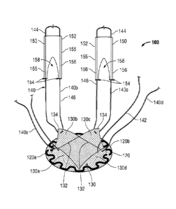
[0017] Fig. 1 is a top, perspective view of one embodiment of a hernia
repair device
provided in accordance with the present disclosure;
[0018] Fig. 2 is a top view of the hernia repair device of Fig. 1;
- 4 -
CA 02853562 2014-04-24
WO 2013/049791 PCT/US2012/058241
[0019] Fig. 3 is a side view of a retracting member of the hernia repair
device of Fig.
1;
[0020] Fig. 4 is a longitudinal, cross-sectional view of the hernia repair
device of Fig.
1 positioned within a tissue defect wherein the retracting members are
disposed in a
first position;
[0021] Fig. 5 is a longitudinal, cross-sectional view of the hernia repair
device of Fig.
1 positioned within the tissue defect wherein the retracting members are
disposed in a
second position;
[0022] Fig. 6 is a longitudinal, cross-sectional view of the hernia repair
device of Fig.
1 retracting tissue surrounding the tissue defect; and
[0023] Fig. 7 is a transverse, cross-sectional view of the hernia repair
device of Fig.
1 retracting tissue surrounding the tissue defect.
DETAILED DESCRIPTION
[0024] Embodiments of the present disclosure are described in detail with
reference
to the drawing figures wherein like reference numerals identify similar or
identical
elements. As used herein, the term "distal" refers to the portion that is
being described
which is further from a user, while the term "proximal" refers to the portion
that is being
described which is closer to a user.
[0025] Referring now to Figs. 1-3, one embodiment of a hernia repair device
provided in accordance with the present disclosure is shown generally
identified by
reference numeral 100. Hernia repair device 100 includes a surgical mesh 110
configured for insertion into a tissue defect "D" (see Figs. 4-6). Surgical
mesh 110
defines a generally flat, circular configuration (although other
configurations are
- 5 -
CA 02853562 2014-04-24
WO 2013/049791 PCT/US2012/058241
contemplated) and is dimensioned to extend across the tissue defect "D" (Figs.
4-6). It
is envisioned that mesh 110 be flexible to conform to the anatomy of the
defect "D"
(Figs. 4-6) and tissue surrounding the defect "D" (Figs. 4-6). Mesh 110 may be
formed
from any suitable biomaterial, e.g., synthetic biomaterials or natural
materials, including
bioabsorbable and biodegradable materials.
[0026] Mesh 110 may also include at least one bioactive agent. The term
"bioactive
agent", as used herein, is used in its broadest sense and includes any
substance or
mixture of substances that have clinical use. A bioactive agent could be any
agent that
provides a therapeutic or prophylactic effect, a compound that affects or
participates in
tissue growth, cell growth, cell differentiation, an anti-adhesive compound, a
compound
that may be able to invoke a biological action such as an immune response, or
could
play any other role in one or more biological processes. For example, surgical
mesh
110 may be coated with an anti-adhesive, e.g., on a distal surface thereof, to
inhibit
adhesion of mesh 110 to tissue and/or with a local anesthetic for temporary
pain relief
during implantation. It is envisioned that the bioactive agent may be applied
to surgical
mesh 110 in any suitable form of matter, e.g., films, powders, liquids, gels,
combinations
thereof, and the like.
[0027] With continued reference to Figs. 1-3, hernia repair device 100
includes a pair
of support members 120a, 120b (collectively support assembly 120) coupled to
surgical
mesh 110. Support assembly 120 is formed from two support members 120a, 120b
(although greater or fewer than two support members 120a, 120b are
contemplated), as
best shown in Fig. 2, that cooperate to define the generally annular-shaped
support
assembly 120. Support assembly 120 may be disposed on a proximal surface of
mesh
- 6 -
CA 02853562 2014-04-24
WO 2013/049791 PCT/US2012/058241
110 toward an outer periphery thereof, e.g., annularly about the circular mesh
110, and
may be engaged to mesh 110 in any suitable fashion, e.g., adhering, welding,
etc.
Support assembly 120 is configured to provide structural support to surgical
mesh 110,
while also permitting surgical mesh 110 to being inserted into and positioned
within the
tissue defect "D" (Figs. 4-6). As such, support assembly 120 may be formed
from a
resiliently flexible material, or any other suitable flexible, or semi-rigid
material. Further,
as shown in Figs. 1 and 2, support assembly 120 may be generally annular in
shape
and may define a serpentine configuration along the length thereof, although
other
configurations are contemplated. Additionally, support members 120a, 120b of
support
assembly 120 may be engaged to one another, e.g., to form a continuous support
assembly 120, or, as shown in the Figures, may define a plurality of gaps,
e.g., two (2)
gaps, therebetween.
[0028] Referring now to Figs. 1 and 2, hernia repair device 100 includes a
plurality of
tissue retracting flaps 130 coupled to mesh 110, e.g., four (4) tissue
retracting flaps
130a-d. Each tissue retracting flap 130 includes a fixed end 132 engaged to
mesh 110
toward an outer periphery thereof, e.g., via adhering, welding, stitching,
etc. Tissue
retracting flaps 130 extend inwardly from the outer periphery of mesh 110 to
free ends
134. More specifically, tissue retracting flaps 130 may define substantially
triangular-
shaped configurations wherein the base constitutes fixed end 132 and wherein
the apex
constitutes free end 134. Tissue retracting flaps 130 may be formed from any
suitable
material including surgical mesh materials, e.g., synthetic biomaterials or
natural
materials, including bioabsorbable and biodegradable materials. As will be
described in
greater detail below, tissue retracting flaps 130 are moveable relative to
surgical mesh
- 7 -
CA 02853562 2014-04-24
WO 2013/049791 PCT/US2012/058241
1 10 between a first position, wherein tissue retracting flaps 130 are
substantially co-
planar with mesh 110 (see Fig. 5), and a second position, wherein tissue
retracting flaps
130 extend proximally from mesh 110 (see Fig. 6).
[0029] Still referring to Figs. 1 and 2, a loop of filament 140, e.g.,
suture, threading,
wire, etc., is coupled to each of the tissue retracting flaps 130a-d toward
the free ends
134 thereof. More specifically, each filament loop 140a-d is disposed through
a
corresponding tissue retracting flap 130a-d, e.g., through the mesh, in
embodiments
where tissue retracting flaps 130 are formed from a surgical mesh material, at
a first end
142 thereof and extends therefrom to second end 144. An intermediate segment
146
interconnects the first and second ends 142, 144, respectively, of filament
loops 140a-
140d. Alternatively, filament loops 140 may be secured to tissue retracting
flaps 130 in
any other suitable fashion. It is also envisioned that multiple filament loops
140 are
secured to each tissue retracting flap 130 or that one filament loop 140 is
secured to
multiple tissue retracting flaps 130.
[0030] Referring now to Figs. 1 and 3, each filament loop 140 includes a
tissue
retracting member 150 slidably disposed thereon. More specifically, each
tissue
retracting member 150 includes a base 152 and a pair of lumens 154 extending
therethrough. Each lumen 154 is configured to slidably receive a length of
filament loop
140 therethrough such that tissue retracting member 150 may be slid along
filament
loop 140 from a position spaced-apart from the tissue retracting flap 130 (see
Fig. 4),
e.g., at the second end 144 of filament loop 140, to a position adjacent
tissue retracting
flap 130 (see Fig. 5), e.g., at the first end 142 of filament loop 140. Base
152 of tissue
- 8 -
CA 02853562 2014-04-24
WO 2013/049791 PCT/US2012/058241
retracting member 150 may be formed from any suitable biocompatible material,
e.g., a
polymer, and be substantially rigid, semi-rigid, or flexible in configuration.
[0031] Tissue retracting member 150, as best shown in Fig. 3, further
includes a pair
of fingers 156 that extend from a distal end 155 thereof. Each lumen 154
extends
through one of the fingers 156. Thus, as can be appreciated, filament loop 140
is
configured to extend through base 152 and both of the fingers 156 of tissue
retracting
member 150. Further, a fixation window 158 is defined between fingers 156 to
facilitate,
as will be described in greater detail, securing of tissue retracting flaps
130 (see Figs. 1-
2) to a distal surface of tissue surrounding the tissue defect "D" (Figs. 4-
6).
[0032] Turning now to Figs. 4-7, the use and operation of hernia repair
device 100
will be described. Initially, hernia repair device 100 is inserted through the
tissue defect
"D" to a distal side of the tissue defect "D." Due to the flexible
configuration of surgical
mesh 110 and the resiliently flexible configuration of support assembly 120,
hernia
repair device 100 may be folded, rolled, bent, or otherwise manipulated to
facilitate
passage through the tissue defect "D" with minimal trauma to surrounding
tissue. Once
inserted through the tissue defect "D," as shown in Figs. 4-5, hernia repair
device 100 is
oriented such that support assembly 120 is substantially annularly disposed
about the
tissue defect "D" with tissue retracting flaps 130 positioned adjacent the
distal surface of
tissue. At this point, as shown in Fig. 5, tissue retracting flaps 130 remain
disposed in
the first position, wherein tissue retracting flaps 130 are substantially co-
planar with
mesh 110. Further, in this position, free ends 134 of tissue retracting flaps
130 are
positioned adjacent to and distal of the tissue defect "D," thus allowing
filament loops
140 to extend proximally though the tissue defect "D."
- 9 -
CA 02853562 2014-04-24
WO 2013/049791 PCT/US2012/058241
[0033] With reference to Figs. 4 and 5, once hernia repair device 100 is
positioned
as mentioned above, tissue retracting members 150 may be slid into position.
More
specifically, tissue retracting members 150, lead by fingers 156, are slid
distally along
and relative to filament loops 140 in the direction of arrows "R." As best
shown in Fig. 5,
tissue retracting members 150 are translated from the first position (Fig. 4)
to the
second position (Fig. 5), wherein tissue retracting members 150 are positioned
adjacent
tissue retracting flaps 130 and at least partially between mesh 110 and a
distal surface
of tissue surrounding the tissue defect "D."
[0034] As shown in Fig. 5, with tissue retracting members 150 in position
adjacent
tissue retracting flaps 130, hernia repair device 100 may be positioned and
secured to
tissue surrounding the tissue defect "D." In order to position hernia repair
device 100,
the clinician grasps filament loops 140 and pulls proximally, in the direction
of arrows
"P," such that tissue retracting flaps 130 and, ultimately, mesh 110 and
support
assembly 120, are pulled proximally to move mesh 110 into approximation with
the
distal surface of tissue surrounding the tissue defect "D" and to
automatically center
mesh 110 relative to the tissue defect "D."
[0035] With continued reference to Fig. 5, in conjunction with Figs. 6 and
7, further
proximal pulling of filament loops 140 effects movement of tissue retracting
flaps 130
from the first, substantially co-planar position relative to mesh 110 to the
second,
extended position relative to mesh 110, while mesh 110 is maintained in an
approximated position adjacent the distal surface of tissue surrounding the
tissue
defect"D" by support assembly 120. As tissue retracting flaps 130 are pulled
toward the
extended position, tissue adjacent the tissue defect "D" is retracted upwardly
and
- 10 -
CA 02853562 2014-04-24
WO 2013/049791 PCT/US2012/058241
outwardly to expose at least a portion of the distal surface of tissue. Tissue
retracting
members 150, which, as mentioned above, are positioned adjacent tissue
retracting
flaps 130, are likewise moved upwardly and outwardly as filament loops 140 are
pulled
proximally to facilitate the retraction of tissue surrounding the tissue
defect "D."
[0036] As best shown in Fig. 7, with the distal surface of tissue at least
partially
exposed, the clinician may secure tissue retracting flaps 130 to the distal
surface of
tissue in any suitable fashion, e.g., adhering, tacking, suturing, etc. As
mentioned
above, in the second position, tissue retracting members 150 are positioned
adjacent
tissue retracting flaps 130. More particularly, fingers 156 of tissue
retracting members
150 are positioned adjacent the respective tissue retracting flaps 130. As can
be
appreciated, in this position, fixation window 158 provides an opening to
provide the
clinician with better visualization at the fixation point and through which
surgical
instrumentation (not shown) for securing tissue retracting flaps 130 to the
distal surface
of tissue may be inserted. Further, fixation window 158 also serves as a guide
for
securing tissue retracting flaps 130 to tissue, helping to ensure that tissue
retracting
flaps 130 are secured to tissue at an appropriate position to maintain mesh
110 in
position during the healing process.
[0037] Thereafter, once hernia repair device 100 has been secured to the
distal
surface of tissue surrounding the tissue defect "D," the clinician may
translate tissue
retracting members 150 proximally from the second position back to the first
position
(see Fig. 4) and release filament loops 140, allowing tissue retracting flaps
130 to return
to the first position under the urging of tissue surrounding the tissue defect
"D" back to
an at-rest, or un-retracted position. Thereafter, filament loops 140 may be
removed,
- 11 -
CA 02853562 2014-04-24
WO 2013/049791 PCT/US2012/058241
e.g., cut-off, from tissue retracting flaps 130, leaving mesh 110 secured
within the tissue
defect "D."
[0038] Hernia repair devices of the present disclosure include a surgical
mesh
configured to extend across a tissue defect, a plurality of filament loops
coupled to the
surgical mesh in proximity of an outer periphery thereof, and a tissue
retracting member
slidably disposed about each of the filament loops. Each of the tissue
retracting flaps is
configured for slidable movement about the filament loop between a first
position,
wherein the tissue retracting member is spaced-apart from the surgical mesh,
and a
second position, wherein the tissue retracting member is positioned adjacent
the
surgical mesh to facilitate the retraction of tissue surrounding the tissue
defect.
[0039] In any of the presently disclosed embodiments, a plurality of tissue
retracting
flaps is coupled to the surgical mesh in proximity of an outer periphery of
the surgical
mesh. The flaps are coupled to the surgical mesh at fixed ends thereof and
extend
inwardly therefrom to free ends thereof. Each flap is moveable about the fixed
end
thereof between a first position, wherein the flaps are substantially co-
planar with the
surgical mesh, and a second position, wherein the flaps extend from the
surgical mesh
to retract tissue surrounding the tissue defect. A filament loop may be
coupled to each
of the tissue retracting flaps. Each flap may define a generally triangular-
shaped
configuration having an apex at the free end thereof such that the filament
loop may be
coupled to the flaps toward the apexes thereof. Further, in any embodiment,
the flaps
may be formed from surgical mesh.
- 12 -
CA 02853562 2014-04-24
WO 2013/049791 PCT/US2012/058241
[0040] In any of the presently disclosed embodiments, a resiliently
deformable
support assembly may be coupled to the surgical mesh to provide structural
support to
the surgical mesh. In fact, the surgical mesh may define a substantially
circular
configuration such that the support assembly may be annularly disposed about
the
surgical mesh in proximity of the outer periphery of the surgical mesh. The
support
member may also define a serpentine-shaped configuration along at least a
portion of a
length thereof.
[0041] In any of the presently disclosed embodiments, the tissue retracting
member
includes first and second spaced-apart lumens extending therethrough. Each of
the first
and second lumens configured to slidably receive a portion of the filament
loop
therethrough. The tissue retracting member may also include a fixation window
defined
therethrough, the fixation window configured to facilitate securing of the
surgical mesh
to the distal surface of tissue surrounding the tissue defect.
[0042] From the foregoing and with reference to the various figure
drawings, those
skilled in the art will appreciate that certain modifications can also be made
to the
present disclosure without departing from the scope of the same. While several
embodiments of the disclosure have been shown in the drawings, it is not
intended that
the disclosure be limited thereto, as it is intended that the disclosure be as
broad in
scope as the art will allow and that the specification be read likewise.
Therefore, the
above description should not be construed as limiting, but merely as
exemplifications of
particular embodiments. Those skilled in the art will envision other
modifications within
the scope and spirit of the claims appended hereto.
- 13 -