Note: Descriptions are shown in the official language in which they were submitted.
CA 02853602 2016-04-22
1
ELECTROSTATIC CAPACITANCE FLUID LEVEL SENSOR
BACKGROUND
1. Technical Field
[0001] The present invention relates to an electrostatic
capacitance fluid level sensor detecting an amount of fluid, and
more particularly to an electrostatic capacitance fluid level
sensor having integrally formed hermetic terminals via which the
sensor is mounted on an electrically driven compressor and the
like.
2. Related Art
[0002] Methods of detecting an amount of fluid have been
conventionally known. Electrostatic capacitance sensors have
been proposed as means for detecting an amount of electrically
nonconductive fluid such as oil. This sensor detects the
presence of fluid and an amount of the fluid, using changes in
electrostatic capacitance between electrodes by causing
electrically insulating fluid to penetrate into a space between
the electrodes. For example, the electrodes are disposed in a
cylindrical casing which is electrically insulating or one of
the electrodes is formed into a cylindrical shape. When fluid
flows into and out of the cylindrical member, electrostatic
capacitance between the electrodes changes. An amount of fluid
in the container is measured from the changing electrostatic
capacitance.
CA 02853602 2016-04-22
2
[0004] The electrostatic capacitance fluid level sensors include
a type which can detect continuous changes in an amount of fluid
on a real-time basis as shown in the foregoing prior art documents.
However, the determination to detect a subtle change in the
electrostatic capacitance becomes more difficult as the
measurement is precise. Furthermore, since the determination
changes depending upon a type of liquid and/or a type or size
of the container to which the sensor is mounted, actual gauging
is required.
[0005] For example, FIGS. 6 to 8 show a proposed example of fluid
level sensor having a simplified construction by limiting the
use of the sensor only to detection of presence of fluid but not
a continuous detection of fluid amount. The fluid level sensor
101 includes a base 102 to which two conductive pins 104
are fixed. The pins 104 have distal ends to which metal electrode
plates 105 are fixed by welding and configured to face each other
substantially in parallel with each other.
[0006] While the above-described fluid level sensor has a simple
structure, a slight tilt of each electrode plate caused by the
welding to the conductive pin changes an interelectrode distance.
Accordingly, adjustment of interelectrode distance is necessary
in order that the tilt caused during the welding may be removed
for the purpose of uniforming the sensitivity. In particular,
CA 02853602 2016-04-22
3
a slight tilt of the welded part has a large influence on the
interelectrode distance as the electrodes are rendered long so
that areas of the electrodes are increased for the purpose of
obtaining electrostatic capacitance. Furthermore, since the
cantilevered electrodes are bared, there is a possibility that
the electrodes may be deformed when subjected to a force during
assembly. Furthermore, when the strength of the electrodes is
increased by thickening the electrodes for prevention of
deformation, stress concentrates on welded parts which are
relatively weaker. This has a possibility of changing the
positional relationship of the electrodes.
[0007] Even when electrodes are adjusted to a proper positional
relationship in manufacture, an increase in the internal
pressure expands the base in the case where the sensor is
mounted to a motor compressor. This slightly changes an angle
between electrically conductive pins, resulting in a large
change in the distance between electrode plates mounted on the
distal ends of conductive pins. Accordingly, the electrostatic
capacitance between the electrodes changes with the result of
a problem that the performance of the fluid level sensor is
reduced.
[0008] Furthermore, since two pieces of electrode are welded on
the same straight line connecting between the conductive pins,
one welding electrode needs to be inserted between the conductive
pins. Furthermore, the firstly fixed electrode gets in the way
of the welding of the second electrode. Additionally, the
interelectrode spacing and the electrodes become slenderer and
thinner as the sensor is small-sized, with the result of a problem
CA 02853602 2016-04-22
4
that a sufficient pressure applied between the electrodes during
welding cannot be obtained.
[0009] Accordingly, an electrostatic capacitance fluid level
sensor is desired which is simple in the construction and easy
to manufacture and handle.
SUMMARY
[0010] According to one embodiment, an electrostatic
capacitance fluid level sensor includes a hermetic terminal
having a metal base and two electrically conductive terminal
pins inserted through the metal base to be hermetically
insulated and fixed, a detection unit including two
electrodes provided on the hermetic terminal for detection
of fluid level by electrostatic capacitance and a spacer
fixing the electrodes in a parallel relationship, the spacer
being electrically insulative, and two connecting terminals
configured to connect and fix the two conductive pins to the
two electrodes respectively. The detection unit is disposed
between the two conductive pins. At least one of the two
connecting terminals is deformable by a weaker force than a
force causing the electrodes to deform.
[0011] Each connecting terminal is formed of a thinner
metal plate than each electrode thereby to be deformable
or each connecting terminal includes a bend diverted to
an extent such that each connecting terminal is
deformable. As a result, the connecting terminal is
deformable by a weaker force than a force causing the
electrodes to deform, whereby stress applied to the detection
CA 02853602 2016-04-22
unit can be widely dispersed to the whole connecting terminal.
[0012]
Furthermore, one of the connecting terminals has a
larger thickness than the other thereby to have a sufficient
stiffness to hold the detection unit, with the result that
5 the strong fixing to the hermetic glass terminal and stress
dispersion can be achieved at the same time more easily.
[0013] According to the fluid level sensor in accordance with
the invention, the detection unit having a fixed positional
relationship between the electrodes is constructed as the fluid
level detection part, whereby a work for adjusting positional
relationship between the electrodes can be rendered easier.
Furthermore, the connecting terminal fixing the detection unit
can disperse/relax stress caused by error in the assembly of
components during the fixing of the detection unit and almost
all of the force caused by deformation of the hermetic terminal.
This can avoid deformation or breakage of the detection unit due
to stress concentration. Accordingly, the performance of the
fluid level sensor can be retained even in the use under severe
conditions.
[0014] Furthermore, since one of the connecting terminals is
constructed to have a sufficient stiffness and the other
connecting terminal is constructed to be flexible, the reliable
retention of the detection unit and dispersion/relaxation of
stress can be achieved at the same time.
BRIEF DESCRIPTION OF THE DRAWINGS
[0015] FIG. 1 is an overhead view of an electrostatic capacitance
ak 02853602 2016-04-22
6
liquid surface sensor in accordance with the invention;
FIG. 2 is a sectional view of the liquid surface sensor as
shown in FIG. 1;
FIG. 3 is a sectional view taken along line A-A in FIG. 2;
FIG. 4 is a partially sectional view of the liquid surface
sensor in accordance with another embodiment of the invention;
FIG. 5 is a partially sectional view of the liquid surface
sensor in accordance with further another embodiment of the
invention;
FIG. 6 is an overhead view of a conventional liquid surface
sensor;
FIG. 7 is a sectional view of the liquid surface sensor in
FIG. 6; and
FIG. 8 is a front view of the liquid surface sensor in FIG.
6.
DETAILEDDESCRIPTION
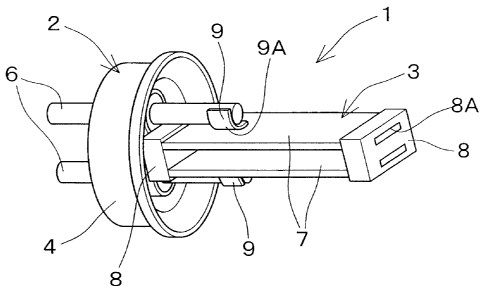
[0016] An electrostatic capacitance fluid level sensor
1 in accordance with the present invention includes a metal
hermetic terminal 2 for use in mounting to a hermetic motor
compressor or the like and a detection unit 3 serving as a
fluid level detecting part. The hermetic terminal 2
includes a cup-shaped metal base 4 and electrically
conductive pins 6 extending through the metal base 4 and
fixed in an insulating manner by an electrically insulating
filler 5 such as glass.
ak 02853602 2014-04-25
7
respectively. The spacers 8 have respective holes 8A into which
distal ends of the electrode plates 7 are inserted to be fixed.
Thus, a positional relationship between the electrode plates 7
is determined as the result of constituting the detection unit
3 together with the spacers 8. Each electrode plate 7 is thick
to have a strength such that each electrode plate 7 does not bow
in a normal use. As a result, the box shape of the detection
unt 3 an,-.1 the positional relationship between the electrode
plates 7 can be reliably retained. Connecting terminals 9 are
welded and fixed to the electrode plates 7 respectively.
[0018] The detection unit 3 is connected via the connecting
terminals 9 to the conductive pins 6 of the airtight terminal
2 by welding thereby to be fixed, respectively. The connecting
terminals 9 are formed by bending metal plates at bends 9A so
as to have generally L-shaped sections, respectively. Since the
connecting terminals 9 are welded to the respective conductive
pins 6 while in parallel to the electrode plates 7, the welding
work can be rendered easier without interference of a welding
electrode with the electrode plates 7 and the conductive pins
6. Displacement caused during welding or stress applied to the
detection unit in normal handling or normal use would deform the
electrodes. However, since the connecting terminals 9 are
thinner than the electrode plates 7 and elastically bendable,
the connecting terminals 9 are deformed before deformation of
the electrodes due to the aforesaid stress. This can reduce
deformation of the electrodes and resultant changes in the
electrostatic capacitance between the electrodes. Accordingly,
even if expansion of the metal hermetic terminal 2 due to an
CA 02853602 2016-04-22
8
increase in the pressure in a compressor casing in the application
to a hermetic motor compressor slightly displaces or changes the
positional relationship between the conductive pins 6, a stable
reference value can be obtained without substantial influences
on the interelectrode distance.
Embodiment 1
[0019] FIG. 4 shows a fluid level sensor 21 in which the bends
29A of the connecting terminals 29 are diverted to a large extent
so that the lengths of the connecting terminals 29 are rendered
longer than an actual distance between secured portions. As a
result, since each entire connecting terminal becomes easier to
bow against a force applied thereto, stress applied to each
connecting terminal 29 is widely dispersed without concentration
on a part of each connecting terminal 29.
Embodiment 2
[0020] High technological capability is required in order to
obtain an adequate retention strength by combining two
connecting terminals after the connecting terminals have been
constructed to attain balances between strength and elasticity.
In view of this, one connecting terminal 39A is constructed to have
a high stiffness by increasing the plate thickness in a fluid
level sensor 31 as shown in FIG. 5. Furthermore, the other
connecting terminal 39B is constructed to be thinner and more
elastic as well as has an increased length by diverting a bend
39B1 to a large extent in the same manner as the foregoing
embodiment. Accordingly, while the connecting terminal 39A can
strongly fix the detection unit 3 to the lead terminals 6, the
connecting terminal 39B can elastically absorb warp caused
CA 02853602 2014-04-25
9
during welding and dimensional changes. Although the connecting
terminal 39B is formed by machining a metal plate in the
embodiment, the connecting terminal 39B may be constructed to
use plastic deformation by a more flexible conductive wire or
the like.
[0021] Furthermore, although the distal ends of the electrode
plates are inserted into the insulating spacers to be fixed
thereby to constitute the detection unit in the foregoing
embodiments, parts to be inserted are not necessarily limited
to the distal ends if the detection unit 3 can be handled without
change in the positional relationship between the electrodes
during the fixing and other handling thereof. For example, the
electrode plates and the spacers may be structured so that the
distal ends of the electrode plates protrude through the spacers
respectively.