Note: Descriptions are shown in the official language in which they were submitted.
CA 02853615 2015-04-15
INTEGRATED DEVICE FOR NUCLEIC ACID DETECTION AND IDENTIFICATION
REFERENCE TO A SEQUENCE LISTING, A TABLE, OR COMPUTER PROGRAM
Applicant hereby submits a sequence listing as a text file titled
042012_ST25.txt created
on April 20, 2012 having 2K kbytes that is ASCII compliant.
BACKGROUND OF THE INVENTION
Field of the Invention (Technical Field):
Embodiments of the present invention relate to an integrated device and
related
methods for detecting and identifying nucleic acids. The device may be fully
disposable or may
comprise a disposable portion and a reusable portion.
Background Art:
Note that the following discussion refers to a number of publications and
references. Discussion of such publications herein is given for more complete
background of
the scientific principles and is not to be construed as an admission that such
publications are
prior art for patentability determination purposes.
As the public health impact and awareness of infectious and emerging diseases,
biothreat agents, genetic diseases and environmental reservoirs of pathogens
has increased,
the need for more informative, sensitive and specific point-of-use rapid
assays has increased
the demand for
1
CA 02853615 2014-04-25
WO 2012/145730
PCT/US2012/034596
polymerase chain reaction (PCR)-based tools. Nucleic acid-based molecular
testing by such
methods as PCR-based amplification is extremely sensitive, specific and
informative.
Unfortunately, currently available nucleic acid tests are unsuitable or of
limited utility for field use
because they require elaborate and costly instrumentation, specialized
laboratory materials and/or
multiple manipulations dependent on user intervention. Consequently, most
samples for molecular
testing are shipped to centralized laboratories, resulting in lengthy turn-
around-times to obtain the
required information.
To address the need for rapid point-of-use molecular testing, prior efforts
have focused on
product designs employing a disposable cartridge and a relatively expensive
associated
instrument. The use of external instrumentation to accomplish fluid movement,
amplification
temperature control and detection simplifies many of the engineering
challenges inherent to
integrating the multiple processes required for molecular testing.
Unfortunately, dependence upon
elaborate instrumentation imposes tremendous economic barriers for small
clinics, local and state
government and law enforcement agencies. Further, dependence upon a small
number of
instruments to run tests could cause unnecessary delays during periods of
increased need, as
occurs during a suspected biowarfare agent release or an emerging epidemic.
Indeed, the
instrument and disposable reagent cartridge model presents a potentially
significant bottleneck
when an outbreak demands surge capacity and increased throughput.
Additionally,
instrumentation dependence complicates ad hoc distribution of test devices to
deployment sites
where logistic constraints preclude transportation of bulky associated
equipment or infrastructure
requirements are absent (e.g. reliable power sources).
Gravity has been described as a means of fluid movement in existing
microfluidic devices.
However, the typical device does not allow for programmable or electronic
control of such fluid
movement, or the mixing of more than two fluids. Also, some devices utilize a
pressure drop
generated by a falling inert or pre-packaged fluid to induce a slight vacuum
and draw reactants into
processing chambers when oriented vertically, which increases storage and
transport complexities
to ensure stability of the pre-packaged fluids. Existing devices which teach
moving a fluid in a
plurality of discrete steps require frangible seals or valves between
chambers, which complicates
operation and manufacture. These devices do not teach the use of separate,
remotely located
vents for each chamber.
2
CA 02853615 2014-04-25
WO 2012/145730
PCT/US2012/034596
Typical microfluidic devices typically make use of smaller reaction volumes
than are
employed in standard laboratory procedures. PCR or other nucleic acid
amplification reactions
such as loop mediated amplification (LAMP), nucleic acid based sequence
amplification (NASBA)
and other isothermal and thermal cycling methods are typically conducted in
testing and research
laboratories using reaction volumes of 5 to 100 microliters. These reaction
volumes accommodate
test specimen volumes sufficient to ensure the detection of scarce assay
targets in dilute
specimens. Microfluidic systems that reduce reaction volumes relative to those
employed in
traditional laboratory molecular testing necessarily also reduce the volume of
specimen that can be
added to the reaction. The result of the smaller reaction volume is a
reduction in capacity to
accommodate sufficient specimen volume to ensure the presence of detectable
amounts of target
in dilute specimens or where assay targets are scarce.
SUMMARY OF THE INVENTION
An embodiment of the present invention is a disposable platform for detecting
a target
nucleic acid, the disposable platform comprising a sample chamber for
receiving a sample
comprising the target nucleic acid; an amplification chamber connected via a
first channel to the
sample chamber and connected via a second channel to a first vent pocket; a
labeling chamber
connected via a third channel to the amplification chamber and connected via a
fourth channel to a
second vent pocket; a detection subsystem connected to the labeling chamber
via a fifth channel
and connected via a sixth channel to a third vent pocket; a plurality of
resistive heating elements;
and one or more temperature measuring devices; wherein the vent pockets are
each sealed
from the atmosphere by a heat labile membrane located in a vicinity of one of
the resistive heating
elements. The disposable platform optionally further comprises a sample
preparation stage
comprising an output in direct fluid connection with an input of the sample
chamber. Dimensions of
a substantially flat surface of the amplification chamber are preferably
approximately the same as
dimensions of a substantially flat surface of a resistive heating element in
thermal contact with the
amplification chamber. The amplification chamber is preferably not cooled by
an active cooling
device. The amplification chamber optionally contains an amplification
solution, the sample
chamber optionally comprises a liquid amplification reagent mix or a
lyophilized amplification
reagent mix, and/or the labeling chamber optionally comprises detection
particles. The labeling
3
CA 02853615 2014-04-25
WO 2012/145730
PCT/US2012/034596
chamber is preferably heatable using one of the resistive heating elements.
The detection
subsystem comprises a lateral flow strip that preferably does not comprise
detection particles. The
chambers, the channels, and the vent pockets are preferably located on a fluid
assembly layer and
the electronic elements are preferably located on a separate layer comprising
a printed circuit
board, the separate layer bonded to the fluid assembly layer. The detection
subsystem is
preferably located on the fluid assembly layer or optionally on a second fluid
assembly layer. The
volume of at least one of the chambers is preferably between approximately 1
microliter and
approximately 50 microliters. The disposable platform preferably further
comprises a connector for
docking the disposable platform with a base unit that is not an external
instrument and that
maintains the disposable platform in a vertical or tilted orientation.
An embodiment of the present invention is a method for detecting a target
nucleic acid, the
method consisting of disposing a sample comprising the target nucleic acid in
a sample chamber
of a disposable platform; orienting the disposable platform vertically or at a
tilt; reacting the sample
with a liquid or previously lyophilized amplification reagent mix; opening a
first vent pocket
connected to an amplification chamber to atmosphere, thereby enabling the
reacted sample to flow
into the amplification chamber; amplifying the target nucleic acid in the
amplification chamber;
opening a second vent pocket connected to a labeling chamber to atmosphere,
thereby enabling
the amplified target nucleic acid to flow into the labeling chamber; labeling
the amplified target
nucleic acid using detection particles in the labeling chamber; opening a
third vent pocket
connected to a detection subsystem to atmosphere, thereby enabling the labeled
target nucleic
acid to flow into the detection subsystem; and detecting the amplified
target nucleic acid. The
amplifying step preferably comprises amplifying the target nucleic acid using
a resistive heating
element located within the disposable platform in a vicinity of the
amplification chamber. The
method preferably further comprises passively cooling the amplification
chamber. The method
preferably further comprises heating the labeling chamber during the labeling
step using a resistive
heating element located within the disposable platform in a vicinity of the
labeling chamber. The
detection subsystem preferably does not comprise detection particles. The
method preferably
further comprises controlling operation of the disposable platform by using a
docking station which
is not an external instrument.
4
CA 02853615 2014-04-25
WO 2012/145730
PCT/US2012/034596
Objects, advantages and novel features, and further scope of applicability of
the present
invention will be set forth in part in the detailed description to follow,
taken in conjunction with the
accompanying drawings, and in part will become apparent to those skilled in
the art upon
examination of the following, or may be learned by practice of the invention.
The objects and
advantages of the invention may be realized and attained by means of the
instrumentalities and
combinations particularly pointed out in the appended claims.
BRIEF DESCRIPTION OF THE DRAWINGS
The accompanying drawings, which are incorporated into and form a part of the
specification, illustrate embodiments of the present invention and, together
with the description,
serve to explain the principles of the invention. The drawings are only for
the purpose of
illustrating certain embodiments of the invention and are not to be construed
as limiting the
invention. In the drawings:
FIG. 1 is a drawing illustrating the fluidic and electronic layers for an
embodiment of the
present invention. Prepared sample fluid enters the sample chamber where it is
mixed with
preferably lyophilized reagents. In the vertical orientation, pressure of the
fluid column equilibrates
with the sealed volume of air below it. Capillarity prevents the escape of air
and further
advancement of fluid. When the appropriate vent seal underlying the
corresponding vent pocket is
ruptured, fluid moves through the outlet channel to the next chamber for
further processing.
Temperature and fluid control is preferably achieved using standard printed
circuit assembly (PCA)
components and assembly techniques.
FIG. 2A is a schematic representation of a vent mechanism employed in an
embodiment
of the present invention to accomplish controlled fluid movement within the
fluidic layer. FIG. 2B
is a drawing illustrating the vent location and construction in an embodiment
of the present
invention. A membrane holds the pressure of the fluid column above ambient.
When sufficient heat
is applied, the membrane ruptures and allows pressure to equilibrate. Fluid
moves along the
hydrostatic pressure gradient. Pressures can be less than a few mBar.
FIG. 3 shows further resistive heater details of an embodiment of the present
invention.
Two 2512 sized thick-film surface mount device (SMD) resistors (heating
element) flank a 0402
sized thermistor (temperature sensor) on the printed circuit board (PCB). A
thin layer of thermal
5
CA 02853615 2014-04-25
WO 2012/145730
PCT/US2012/034596
compound at the interface of the resistor(s) and the amplification chamber
maintains thermal
conductivity to the heaters and sensor. Dimensions of the chamber are
preferably chosen to
maximize the area/volume ratio.
FIG. 4 depicts embodiments of the present invention which support either
thermal cycling
or isothermal-based nucleic acid amplification methodologies. FIG. 4A shows a
PCA with four
resistor/thermistor pairs. Four surface mount resistors serve as four
independently controllable
heaters (arrows). FIG. (B shows a fluidic assembly attached to the PCA of FIG.
4A consistent with
the resistive heater detail of FIG. 3. The fluidic layer interfaces with the
surface mount resistors of
the PCA to provide reaction chambers for nucleic acid amplification. FIG. 40
shows gel
electrophoresis of amplification reactions producing a ¨150 bp (base pair)
product from a PCR
machine (LAB) or by an embodiment of the present invention (pHeater) by
thermal cycling. The left
most lane is size standard. FIG. 4D is a graph of temperature versus time in
seconds for fluid
within the amplification chamber of the present embodiments. The darker line
indicates
temperature of solution in the reaction chamber obtained by thermocouple. The
lighter line is the
temperature measured by the thermistor used by the microcontroller for
temperature control. 40
cycles of a two-temperature PCR reaction can be accomplished in less than 20
minutes using a 20
pL reaction volume. FIG. 4E shows gel electrophoresis of isothermal Nucleic
Acid Sequence
Based Amplification (NASBA) reactions producing an ¨150 bp product from a PCR
machine
(Positive Control), or by use of an embodiment of the present invention. Four
separate reactions
indicate both the setting of the temperature sensor, and a particular surface
treatment applied to
the interior of the fluidic chamber.
FIG. 5 illustrates an embodiment of the present invention comprising the
technique of
transporting fluid without the use of a vent. By heating the chamber below the
fluid column, gas will
expand and purge itself through the inlet channel. Upon cooling, the gas in
the chamber volume
will contract and draw in a volume of fluid proportional to that of the purged
gas. The fluid drops to
the chamber floor. Successive iterations of this cycle can move the full
reaction volume. The
operation of is technique depends on channel size, length, heat time and
temperature, chamber
volumes, and surface energies of components.
FIG. 6 shows the detail and function of a labeling chamber of an embodiment of
the
present invention. Fluid containing amplicon enters the labeling chamber
through the inlet channel
6
CA 02853615 2014-04-25
WO 2012/145730
PCT/US2012/034596
and contacts detection particles. Sufficient mixing is accomplished by heating
or boiling of fluid.
Rising bubbles nucleated at the bottom and sides of the chamber, preferably by
a textured feature
such as a laser etched line or series of lines, preferably effectively stir
the mixture. In this
embodiment, SMD components are the same as those used in the amplification
heater.
FIG. 7 shows the components of the fluidic layer of an embodiment of the
present
invention. A wall component of chosen thickness is bonded on two sides by face
components. In
one embodiment, the wall component is 0.5 mm laser cut acrylic and the faces
are 0.004"
polyester (PET) film. The parts are preferably bonded together with a silicone
transfer adhesive.
Interior surfaces are treated to control wetting. Reagents and lateral flow
assembly are added
during fabrication. An adhesive membrane is preferably sealed over the vent
pockets.
FIG. 8 shows the PCA side facing the fluidic assembly of an embodiment of the
present
invention in which the heating elements are thick-film resistors. The
temperature sensor is a small
SMD thermistor positioned in close proximity to the heaters. The PCA may
optionally incorporate
indicator LEDs for monitoring assay progression, heating, and vent opening.
FIG. 9 is a drawing illustrating the fluid cassette bonded to the PCA with an
adhesive shim
in accordance with an embodiment of the present invention. The shim thickness
can be important
to proper distancing and function of the vents and heaters.
FIG. 10A shows the disposable PCA of a semi-disposable invention configuration
embodiment of the present invention. The PCA contains only electronic
components that interface
with the disposable fluidic assembly. This includes the heating elements,
temperature sensors,
and optionally LED indicators. A connector is present to complete circuitry
and optionally to add
support in the vertical orientation.
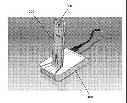
FIG. 10B shows the disposable PCA/fluidic assembly of FIG. 10A in place in a
docking
station. The docking station contains the control electronics and power supply
and is optionally
easily portable and handheld. The disposable portion containing the PCA and
fluidic assemblies
are inserted in the connector, preferably in a vertical orientation. A user
interface including
indicating LEDs, LCD, and user controls may optionally be present in some
embodiments. The
docking station may include buttons to initiate electronic processes required
for the assay.
FIG. 11A is drawing of the front side of the PCA of a disposable invention
configuration
embodiment of the present invention. This side faces the fluidic assembly.
Heating and sensor
7
CA 02853615 2014-04-25
WO 2012/145730
PCT/US2012/034596
elements as well as user interface components such as LED indicators are
present in this
embodiment.
FIG. 11B is a drawing illustrating the layout of the back side of the PCA of
the disposable
invention configuration of FIG. 11A. This side of the PCB holds the control
circuitry such as the
microcontroller, MOSFET switches, and ancillary circuitry. In this embodiment,
terminals are
present for a 9V battery, as well as optional user interface devices such as
tactile switches useful
for assay initiation.
FIG. 110 is a drawing of the PCA of FIG. 11B with 9V battery installed.
Plastic housing is
not shown. Battery placement is preferably as shown to lower the center of
mass and to help
prevent tipping or overturning of device during operation.
FIG. 12 is an illustration of a semi-disposable embodiment of the present
invention
wherein a sample preparation subsystem is interfaced with the amplification
and detection fluidics
and electronics.
FIG. 13 shows the components of an embodiment of a multilayer fluidic layer
incorporated
into a disposable assay.
FIG. 14 shows an exploded view of a disposable assay cartridge incorporating
the fluidic
layer of FIG. 13.
FIG. 15 is an illustration of the assembled disposable PCA/fluidic assembly of
FIG. 14 in
place in a docking station.
FIG. 16 are photographs of the fluidic layers of an embodiment of the present
invention
which supports thermal cycling based nucleic acid amplification and detection.
A reaction solution
containing all reagents necessary to support nucleic acid amplification was
added to the sample
chamber. In FIG. 16A, required enzymes were added to the reaction solution in
liquid form. In FIG.
16B, required enzymes were supplied by incorporation of a lyophilized pellet
into the sample
chamber. The amplification and detection of nucleic acid was performed as
described in Example
1. The top line of the detection strip assembly represents the positive
control, an oligonucleotide
complementary to the detection probe. The line immediately below the positive
control represents
the capture line, an immobilized oligonucleotide complementary to the same
amplification product
strand as the detection probe.
8
CA 02853615 2014-04-25
WO 2012/145730
PCT/US2012/034596
FIGS. 17A and 17B are photographs of an integrated sample-to-result nucleic
acid testing
device fabricated by interfacing a sample preparation sub-system with the
invention. Embodiments
of the present invention support nucleic acid isolation, amplification, and
detection in a single
integrated device. Nucleic acid isolation, amplification, and detection was
performed as described
in Example 2. The top line of the lateral flow assembly represents the
positive control, an
oligonucleotide complementary to the detection probe. The line immediately
below the positive
control represents the capture line, an immobilized oligonucleotide
complementary to the same
amplification product strand as the detection probe. The device is shown
following completion of
processing macerated leaf tissue from a citrus tree suffering from citrus
greening disease and
assaying the nucleic acids isolated by the integrated sample preparation
system for Candidatus
Liberibacter the etiologic agent of citrus greening.
DETAILED DESCRIPTION OF THE INVENTION
Embodiments of the present invention comprise a disposable platform which
integrates
instrumentation independent means of conducting all requisite steps of a
nucleic acid molecular
assay and complements current immuno-lateral flow rapid assays with a new
generation of nucleic
acid tests offering more informative and sensitive analyses. Embodiments of
the present invention
facilitate the broader use of rapid nucleic acid testing in small clinics and
austere settings where
infectious disease, biothreat agent, agriculture and environmental testing are
the most likely to
have the greatest impact. Certain embodiments of the present invention are
completely self-
contained and disposable which enables "surge capacity" in times of increased
demand by
allowing parallel tests to be run without instrumentation-imposed bottlenecks.
Additionally, in those
application areas where a low cost disposable cartridge coupled with an
inexpensive battery-
powered or AC adapter energized docking station is preferable, an embodiment
of the invention
where a simple docking station is employed further reduces test costs by
placing reusable
components in a reusable yet inexpensive base. The platform technology
disclosed herein offers
sensitivity similar to laboratory nucleic acid amplification-based methods,
minimal user intervention
and training requirements, sequence specificity imparted by both amplification
and detection,
multiplex capacity, stable reagents, compatibility with low-cost large-scale
manufacturing, battery
9
CA 02853615 2014-04-25
WO 2012/145730
PCT/US2012/034596
operation to allow use in austere settings, and a flexible platform technology
allowing the
incorporation of additional or alternative biomarkers without device redesign.
Embodiments of the present invention provide systems and methods for low-cost,
point-of-
use nucleic acid detection and identification suitable to perform analyses in
locations remote from
a laboratory environment where testing would ordinarily be performed.
Advantageously, nucleic
acid amplification reaction volumes can be in the same volume range commonly
used in traditional
laboratory testing (e.g. 5-100 pL). The reaction conducted in embodiments of
the present invention
is thus directly comparable to accepted laboratory assays, and allows the
accommodation of the
same specimen volumes typically employed in traditional molecular testing.
Embodiments of the present invention may be used to detect the presence of a
target
nucleic acid sequence or sequences in a sample. Target sequences may be DNA
such as
chromosomal DNA or extra-chromosomal DNA (e.g. mitochondrial DNA, chloroplast
DNA, plasmid
DNA etc) or RNA (e.g. rRNA, mRNA, small RNAs and viral RNA). Similarly,
embodiments of the
invention may be used to identify nucleic acid polymorphisms including single
nucleotide
polymorphisms, deletions, insertions, inversions and sequence duplications.
Further, embodiments
of the invention may be used to detect gene regulation events such as gene up-
and down-
regulation at the level of transcription. Thus, embodiments of the invention
may be employed for
such applications as: 1) the detection and identification of pathogen nucleic
acids in agricultural,
clinical, food, environmental and veterinary samples; 2) detection of genetic
biomarkers of disease;
and 3) the diagnosis of disease or a metabolic state through the detection of
relevant biomarkers
of the disease or metabolic state, such as gene regulation events (mRNA up- or
down regulation
or the induction of small RNAs or other nucleic acid molecules generated or
repressed during a
disease or metabolic state) in response to the presence of a pathogen, toxin,
other etiologic agent,
environmental stimulus or metabolic state.
Embodiments of the present invention comprise a means of target nucleic acid
sample
preparation, amplification, and detection upon addition of a nucleic acid
sample, comprising all
aspects of fluid control, temperature control, and reagent mixing.
In some embodiments of the invention, the device provides a means of
performing nucleic
acid testing using a portable power supply such as a battery, and is fully
disposable. In other
embodiments of the invention, a disposable nucleic acid test cartridge works
in conjunction with a
CA 02853615 2014-04-25
WO 2012/145730
PCT/US2012/034596
simple reusable electronic component which does not perform all of the
functions of typical
laboratory instrumentation.
Embodiments of the present invention provide for a nucleic acid amplification
and
detection device comprising, but not limited to, a housing, a circuit board,
and a fluidic or
microfluidic layer. In certain embodiments, the circuit board may contain a
variety of surface-mount
components such as resistors, thermistors, light-emitting diodes (LEDs), photo-
diodes, and
microcontrollers. The fluidic or microfluidic layer is responsible for moving
aqueous reaction
volumes and may be made from a variety of plastics and by a variety of
manufacturing techniques
including bonding, fusing or lamination of laser cut, water-jet cut or
injection molded pieces. The
fluidics and circuit board components are held together and their thermal
coupling may be
enhanced by heat conducting materials or compounds. The housing preferably
serves in part as a
cosmetic and protective sheath, hiding the delicate components of the
microfluidic and circuit
board layers, and may also serve to facilitate sample input, buffer release,
nucleic acid elution and
the initiation of processes required for device functionality. For example,
the housing may
incorporate a sample input port, a button or similar mechanical feature to
allow user activation,
buffer release, sample flow initiation and/or nucleic acid elution.
In some embodiments of the invention, the fluidic or microfluidic layer
preferably
comprises four chambers, including a sample input chamber, an amplification
chamber, a nucleic
acid labeling chamber, and a detection chamber. The solution input chamber
preferably comprises
a sample input orifice where a nucleic acid containing sample may be added,
and an egress
conduit leading to the amplification chamber. The sample input chamber may
also comprise
lyophilized reagents that may include suitable buffers, salt,
deoxyribonucleotides, ribonucleotides,
oligonucleotide primers, and enzymes such as DNA polymerase and reverse
transcriptase. Such
lyophilized reagents are preferably solubilized upon addition of the nucleic
acid sample. The
amplification chamber is preferably situated in register and thermal contact
with heater elements
on the circuit board. Similarly, electronic components present on the circuit
board are placed in
physical contact or proximity to vents or valve structures in the fluidic
layer to enable electronic
control. The circuit board physical layout is designed to provide registration
with elements of the
fluidic or microfluidic layer such that resistive heating elements of the
circuit board for amplification
11
CA 02853615 2014-04-25
WO 2012/145730
PCT/US2012/034596
and/or fluid flow control are situated to form contacts with elements of the
fluidic component with
which they interact.
Other embodiments of the invention comprise a nucleic acid amplification and
detection
device that is integrated with a sample preparation device. Embodiments
including the sample
preparation device provide a means for the communication of fluids between
sample preparation
subsystem output ports or valves and the input port or ports of the fluidic or
microfluidic
components of the device.
Unless otherwise defined, all terms of art, notations and other scientific
terminology used
herein are intended to have the meanings commonly understood by those of skill
in the art to
which this invention pertains. The techniques and procedures described or
referenced herein are
generally well understood and commonly employed using conventional
methodologies by those
skilled in the art, such as, for example, the widely utilized molecular
cloning methodologies
described in Sambrook et al., Molecular Cloning: A Laboratory Manual 3rd.
edition (2001) Cold
Spring Harbor Laboratory Press, Cold Spring Harbor, N.Y. and Current Protocols
in Molecular
Biology (Ausbel et al., eds., John Wiley & Sons, Inc. 2001. As appropriate,
procedures involving
the use of commercially available kits and reagents are generally carried out
in accordance with
manufacturer defined protocols and/or parameters unless otherwise noted.
As used throughout the specification and claims, the terms 'target nucleic
acid' or
'template nucleic acid' mean a single-stranded or double-stranded DNA or RNA
fragment or
sequence that is intended to be detected.
As used throughout the specification and claims, the terms microparticle' or
'detection
particle' mean any compound used to label nucleic acid product generated
during an amplification
reaction, including fluorescent dyes specific for duplex nucleic acid,
fluorescently modified
oligonucleotides, and oligonucleotide-conjugated quantum dots or solid-phase
elements such as a
polystyrene, latex or paramagnetic particles or microspheres.
As used throughout the specification and claims, the term 'chamber' means a
fluidic
compartment where fluid resides for some period of time before being directed
to another
chamber. For example, a chamber may be the sample chamber, amplification
chamber, labeling
chamber, or the detection chamber.
12
CA 02853615 2015-04-15
As used throughout the specification and claims, the term 'pocket' means a
compartment overlaid onto a resistor or other mechanism that serves as a
venting mechanism.
For example, unlike fluidic chambers as described above, a pocket created in
the fluidic layer
may have one open face that aligns with a resistor on the PCA. This open face
is preferably
covered by a thin membrane to create a sealed cavity that is easily ruptured
by energizing the
underlying resistor.
As used throughout the specification and claims, the term 'channel' means a
narrow conduit within the fluidic assembly which typically connects two or
more chambers
and/or pockets or combinations thereof, including, for example, an inlet,
outlet, or a vent
channel. In the case of an inlet or outlet channel, fluid sample migrates
through the channel. In
the case of a vent channel, the conduit remains clear of fluid and connects a
fluidic chamber to
a vent pocket.
As used throughout the specification and claims, the term "external
instrument" means a
reusable instrument that heats and/or cools a disposable assay, and/or
performs a mechanical
action on a disposable assay, including but not limited to piercing buffer
packets and/or pumping
or otherwise actively providing a transport force for fluids.
Embodiments of the present invention are devices for low-cost, point-of-use
nucleic acid
testing suitable to perform analyses in locations remote from a laboratory
environment where
testing would ordinarily be performed. Certain devices comprise fluidic and
electronic
components or layers, optionally encased by a protective housing. In
embodiments of the
present invention, the fluidic layer is composed of plastic and is a series of
chambers and
pockets connected by narrow channels in which chambers are oriented vertically
with respect to
one another during operation. The fluidic layer is overlaid or otherwise
placed in physical
contact with electronic components such as a printed circuit board containing
off-the-shelf
surface mount devices (SMDs) and controlled via a microcontroller. In some
embodiments of
the device, the entire assembly is disposable. In other embodiments, the
fluidic and physically
bonded electronic layers are disposable, while a small inexpensive controlling
unit is reusable.
In another embodiment, the fluidic layer is disposable, and a small
controlling base unit is
reusable. For all embodiments, the present invention may be integrated with a
nucleic acid
sample preparation device such as that described in International Publication
No. WO
2009/137059 Al, entitled "Highly Simplified Lateral Flow-Based Nucleic Acid
Sample
Preparation and Passive Fluid Flow Control", and/or use methods described
therein.
13
CA 02853615 2014-04-25
WO 2012/145730
PCT/US2012/034596
Embodiments of the present invention comprise an integrated nucleic acid
testing device
that can be manufactured inexpensively with established manufacturing
processes. The invention
provides molecular test data while retaining the simplicity from the end-user
perspective of widely
accepted hand-held immunoassays, overcoming the challenges of regulating fluid
temperatures
within the device, transporting small sample volumes in sequential steps,
reagent mixing, and
detecting nucleic acids. Embodiments of the present invention are uniquely
adapted to utilize off-
the-shelf electronic elements that may be constructed by standard assembly
techniques, and
requires no moving parts. Furthermore, the fluid layer design enables the use
of readily available
plastics and manufacturing techniques. The result is an inexpensive,
disposable, and reliable
device capable of nucleic acid isolation, amplification, and detection without
the need for a
dedicated laboratory infrastructure.
Existing nucleic acid testing devices generally use sophisticated heating
elements such as
deposited film heaters and Peltier devices that add significant cost and/or
require specialized
manufacturing methods. In embodiments of the invention, heating of the
reaction solution is
preferably accomplished by use of simple resistive surface-mount devices that
may be purchased
for pennies or less and are assembled and tested by common manufacturing
standards. By
layering fluidic chambers over these resistive elements and associated sensor
elements, the fluid
temperature of the reaction solutions may be conveniently regulated. The broad
use of SMD
resistors in the electronics industry ensures that the present invention is
amenable to well
established quality control methods. Many nucleic acid amplification
techniques, such as PCR,
require not only rapid heating of the reaction solution but rapid cooling as
well. Reaction chambers
in the present invention are preferably heated on one side and the ambient
temperature across the
opposite face is used to help reduce fluid temperature. In addition, vertical
orientation of
embodiments of the device allows for more rapid cooling by passive convection
than if the device
was oriented horizontally, thus, reducing the thermal cycle period without the
use of costly fans or
Peltier devices.
Fluid control is another challenge associated with low-cost nucleic acid test
device
designs. Devices known in the art generally employ electromechanical,
electrokinetic, or
piezoelectric pumping mechanisms to manipulate fluids during device operation.
These pumping
elements increase both device complexity and cost. Similarly, valves making
use of elaborate
14
CA 02853615 2014-04-25
WO 2012/145730
PCT/US2012/034596
micromechanical designs or moving parts can increase fabrication costs and
reduce reliability due
to complications such as moving part failure or bio-fouling. Unlike previously
described nucleic acid
testing devices, embodiments of the present invention utilize hydrostatic
pressure under
microcontroller control together with capillary forces and surface tension to
manipulate fluid
volumes. The vertical orientation of some embodiments of the present invention
allows for the
reaction solution to cascade from chamber to chamber under microcontroller
control to
accommodate required manipulations of the assay. Fluid may be held in
individual reaction
chambers through a balance of channel size and surface tension, where surface
tension prohibits
fluid advancement by gas displacement. Sample advances to the lower chamber
preferably only
after activation of a simple venting mechanism under microcontroller control.
Once open, the vent
allows fluid to move from a first chamber to a second chamber by means of
providing a path for
displaced air to escape from the second chamber as fluid enters. Each chamber
within the fluidic
layer preferably connects to a sealed vent pocket through a narrow vent
channel. The vent pocket
is preferably sealed on one face with a thin plastic membrane that is easily
ruptured by heating a
small surface mount resistor underlying the membrane. Once the vent of a lower
chamber is
opened, fluid advancement proceeds, even under low hydrostatic pressures.
As more specifically described below, the fluidic or microfluidic valve
mechanism used in
some embodiments of the present invention preferably employs a heating element
in thermal and
(optional) physical contact with a heat labile seal to enable electronic
control of fluid movement by
means of venting a chamber of lower elevation to allow a fluid from a chamber
of higher elevation
to flow into the lower chamber. In one embodiment, a surface mount resistor is
mounted on a
printed circuit board, using widely used and well-established electronics
manufacturing methods,
and placed in physical contact with a channel seal composed of heat labile
material. When
energized the surface mount resistor generates sufficient heat to rupture the
seal, which results in
the venting of the chamber to lower pressure, such as ambient pressure, thus
allowing the
movement of fluid from a chamber of higher elevation to a chamber of lower
elevation. A direct
seal between higher and lower elevation chambers is preferably not employed.
The channel and
seal may be located remotely from the fluid chambers, thus facilitating
fluidic device layout in
configurations efficient for manufacture. The seal material may comprise any
material that can seal
the vent channel and be ruptured from heating as described, for example a thin
plastic sheet. This
CA 02853615 2014-04-25
WO 2012/145730
PCT/US2012/034596
approach to fluid movement control in the apparatus benefits from low
materials costs, suitability
for manufacture using established lamination and electronics manufacturing
techniques while
providing the capacity to move fluids through a series of chambers under the
control of electronic
control circuits such as microprocessors or microcontrollers. The use of
vents, a heat labile
material to seal the vents (and not to seal the fluid chambers or fluid
microchannels themselves)
and an electronic means of breaking said seal with heat provides a means of
controlling fluid flow
through the device to enable movement of fluid at predetermined times or
following the completion
of specific events (for example, attaining a temperature, a temperature change
or a series of
temperature changes, or the completion of an incubation time or times or other
events).
In addition, the vent approach has a number of advantages over sealing the
fluid
chambers themselves. Vent pockets can be located anywhere on the fluidics
layout and simply
communicate with the chamber they regulate via a vent channel. From a
manufacturing
standpoint, vent pockets can be localized so that only a single sealing
membrane for all vent
pockets (which may comprise a vent pocket manifold) is affixed to the fluidic
layer, preferably by
well established methods such as adhesives, heat lamination, ultrasonic
welding, laser welding
etc. In contrast, directly sealing a fluid chamber requires that the seal
material be placed at
different locations corresponding to each chamber location, which is more
difficult to manufacture.
This presents a more challenging scenario during manufacture compared to a
single vent pocket
manifold sealed by a single membrane.
In addition, sealing material located at the chamber will likely come into
contact with the solution
held in the chamber. This requires the use of a material that (i) does not
interfere with the reactions
conducted in the chamber, and (ii) is not affected by the solution. Given the
sensitivity of the
biochemical reactions to chemical inhibitors and the elevated temperatures
used for both
amplification and labeling prior to detection, the list of acceptable
materials becomes limited.
Furthermore, the physical proximity of heat sensitive material directly
associated with reaction
chambers used to conduct reactions at elevated temperatures presents a
significant challenge to
ensure thermal isolation of the valve sealing material from the elevated
temperatures employed
during the reactions, in addition to preventing the solution from heating up
when the sealing
material is melted. To avoid valve failure, the heat sensitive material must
be remotely located
relative to the heat source or the heat sensitive material must be activated
at temperatures well
16
CA 02853615 2014-04-25
WO 2012/145730
PCT/US2012/034596
above the highest temperature employed in the reactions. Remotely locating
seals directly
associated with chambers in a miniaturized device imposes constraints on
fluidics layouts that
impede the use of compact physical designs. And the use of higher temperatures
to trigger valves
located at the reaction chamber site can be deleterious to biochemical
components that lose
stability slightly above the employed reaction temperatures. Finally, if
chambers are directly
sealed, melted sealing material can remain in the channels between chambers,
occluding
flow. The viscosity of the sealing material may require more pressure in the
fluid column than is
obtained in a miniaturized gravity driven apparatus.
In embodiments of the present invention, reagent mixing requires no more
complexity than
other systems. Reagents necessary for nucleic acid amplification such as
buffers, salts,
deoxyribonucleotides, oligonucleotide primers, and enzymes are preferably
stably incorporated by
use of lyophilized pellets or cakes. These lyophilized reagents, sealed in a
fluidic chamber, may be
readily solubilized upon contact with aqueous solution. In the case that
additional mixing is
required, the vertical orientation of embodiments of the present invention
offers opportunities for
novel methods of mixing solutions. By utilizing heaters underlying fluidic
chambers, gas may be
heated, delivering bubbles to the reaction solution in the chamber above when
the solution
contains thermally-sensitive components. Alternatively, heaters may be used to
directly heat a
solution to the point that boiling occurs, in the case that the solution
contains no thermally-sensitive
components. The occurrence of air bubbles is often undesirable in previously
disclosed fluidic and
microfluidic devices, as they may accumulate in fluidic chambers and channels
and displace
reaction solutions or impede fluid movement within the device. The vertical
design of embodiments
of the invention presented herein allows bubbles to rise to the fluid surface,
resulting in only
minimal and transient fluid displacement, effectively ameliorating any
disadvantageous impacts of
bubbles on the fluidic or microfluidic system. Mixing by boiling is also
convenient with this vertical
design, as fluid displaced during the process simply returns to the original
fluidic chamber by
gravity after the heating elements are turned off.
In embodiments of the invention, a colorimetric detection strip is used to
detect amplified
nucleic acids. Lateral flow assays are commonly used in immuno-assay tests due
to their ease of
use, reliability, and low cost. The prior art contains descriptions of the use
of lateral flow strips for
the detection of nucleic acids using porous materials as a sample receiving
zone which is at or
17
CA 02853615 2014-04-25
WO 2012/145730
PCT/US2012/034596
near a labeling zone also comprised of a porous material and placed at or near
one end of the
lateral flow assay device. In these prior inventions labeling moieties are in
the labeling zone. The
use of porous materials to comprise the sample receiving zone and the labeling
zone results in the
retention of some sample solution as well as detection particles in the porous
materials. Although
labeling zones comprising porous materials having reversibly immobilized
moieties required for
detection may be used in embodiments of the present invention, embodiments of
the present
invention preferably utilize detection particles or moieties held in a region
of the device distinct
from the sample receiving zone of the lateral flow strip and comprising
nonporous materials with
low fluid retention characteristics. This approach allows nucleic acid target
containing samples to
be labeled prior to introduction to the porous components of the sample
receiving end of the lateral
flow component of the device and thereby eliminates the retention and/or loss
of sample material
and detection particles in a porous labeling zone. This method further enables
the use of various
treatments of the sample in the presence of detection moieties, such as
treatment with high
temperatures, to accomplish denaturation of a double-stranded target or
secondary structures
within a single-stranded target without concern for the impacts of temperature
on porous sample
receiving or labeling zone materials or the lateral flow detection strip
materials. Additionally, the
use of a labeling zone not in lateral flow contact with the sample receiving
zone but subject to the
control of fluidic components such as vents or valves allows target and label
to remain in contact
for periods of time controlled by fluid flow control systems. Thus embodiments
of the present
invention can be different than traditional lateral flow test strips wherein
sample and detection
particle interaction times and conditions are determined by the capillary
transport properties of the
materials. By incorporating the detection particles in a temperature-regulated
chamber,
denaturation of duplex nucleic acid is possible allowing for efficient
hybridization-based detection.
In alternative embodiments, fluorescence is used to detect nucleic acid
amplification using a
combination of LEDs, photodiodes, and optical filters. These optical detection
systems can be
used to perform real-time nucleic acid detection and quantification during
amplification and end-
point detection after amplification.
Embodiments of the invention comprise a low cost, point-of-use system is
provided
wherein a nucleic acid sample may be selectively amplified and detected.
Further embodiments
include integration with a nucleic acid sample preparation device such as that
described in
18
CA 02853615 2014-04-25
WO 2012/145730
PCT/US2012/034596
International Publication No. WO 2009/137059 Al, entitled "Highly Simplified
Lateral Flow-Based
Nucleic Acid Sample Preparation and Passive Fluid Flow Control". An embodiment
of the device
preferably comprises both a plastic fluidic component and printed circuit
assembly (PCA), and is
optionally encased in a housing that protects the active components.
Temperature regulation, fluid
and reagent mixing are preferably coordinated by a microcontroller. The
reaction cassette is
preferably oriented and run vertically so that hydrostatic pressure, capillary
forces and surface
tension, in conjunction with microcontroller triggered vents, control fluid
movement within the
device.
Referring to the representative schematic in FIG. 1, a nucleic acid sample is
added to
sample chamber 10. The nucleic acid sample may derive from an online (i.e.
integrated nucleic
acid preparation sub-system), a separate nucleic acid preparation process
(such as one of many
commercially available methods, e.g. spin-columns) followed by addition of the
purified nucleic
acid to the device by pipette, or an unprocessed nucleic acid containing
sample. Preferably
already present in the sample chamber, or alternatively added later, is a
reagent mix, which may
be in liquid or dry form, containing all components necessary for the
amplification reaction, such as
buffering agents, salts, dNTPs, rNTPs, oligonucleotide primers, and/or
enzymes. In some
embodiments the reagent mix is lyophilized to form lyophilized reagents 20.
Introduction of the
sample to the sample chamber causes reagents and samples to commingle such
that the reagents
act upon the sample. An optional bubble-mixing step to further mix the sample
with the reagents or
resuspend the reagents may optionally be performed. Fluid is then preferably
directed through inlet
channel 40 to one or more amplification chamber(s) 30 that reside below the
sample chamber
when the device is in the vertical orientation. Outlet channel 45 connects
amplification chamber 30
to a subsequent chamber. To facilitate multiplexed tests, wherein multiple
amplicons are
generated, multiplexed amplification can be accomplished by deposition of
multiple primer sets
within the amplification chambers. Additionally, circuit board and fluidic
designs in which multiple
amplification and detection chambers are incorporated into the device support
multiple parallel
amplification reactions that may be single-plex or multiplex reactions. This
approach reduces or
eliminates the complications known to those skilled in the art that result
from multiplexed
amplification using multiple pairs of primers in the same reaction. Moreover,
the use of multiple
amplification reaction chambers allows simultaneous amplification under
different temperature
19
CA 02853615 2014-04-25
WO 2012/145730
PCT/US2012/034596
regimens to accommodate requirements for optimal amplification, such as
different melting or
annealing temperatures required for different target and/or primer sequences.
Fluid movement from a first chamber to a second chamber of the device is
preferably
accomplished by the opening of a vent connected to the second chamber as shown
in FIGS. 1-2.
One embodiment of the vent comprises two components, vent pocket 50, one face
of which
comprises a membrane such as polyolefin and is in contact with a resistor
mounted to the printed
circuit board assembly (RCA) 75, and vent channel 60 that connects vent pocket
50 to the
microfluidic compartment under its control. When fluid is first added to the
system at the sample
chamber, the vent, connected to the downstream chamber, is sealed and fluid
will not pass
through the channel connecting the two chambers. A microcontroller is
responsible for sending
electrical current to a heating element, such as resistor 70, located at or
near the membrane that
comprises one face of vent pocket 50. Heat produced by the energized resistor
disrupts thin
membrane 80, thus opening the vent. Once open, the vent allows fluid to drop
from the first
chamber to the second chamber by means of providing a path for displaced air
to escape from the
second chamber as fluid enters. Other embodiments of the vent pocket may
comprise seals other
than a heat-sensitive membrane, and may utilize other methods of breaking the
seals, such as
puncturing, tearing, or dissolving.
The amplification chamber is preferably in contact with heater elements to
provide a
means for the temperature regulation necessary to support nucleic acid
amplification. In some
embodiments of the invention the amplification chamber may contain
oligonucleotides on at least a
portion of the interior surface. As shown in FIGS. 1-3, an embodiment of the
device comprises inlet
channel 30 leading from sample chamber 10 to amplification chamber 30, outlet
channel 45
preferably leading from amplification chamber 30 to labeling chamber 90, and
vent channel 60
leading to vent pocket 50 as described above. At the interface between the
amplification chamber
wall 95 and heater element(s) 100 it may be advantageous to place a thermally
conductive
material such as a thermal grease or compound. A microcontroller modulates
current to the
preferably resistive heating element(s), preferably by means of metal oxide
semiconductor field
effect transistors (MOSFETs), based upon data collected from temperature
sensor 110, preferably
using simple on/off or proportional integral derivative (RID) temperature
control methods or other
algorithmic temperature control known to those skilled in the art.
CA 02853615 2014-04-25
WO 2012/145730
PCT/US2012/034596
Existing systems employ active heating and cooling devices located in a
reusable
instrument to accomplish temperature control for nucleic acid amplification
taking place in a
disposable cartridge, which necessarily requires an instrument of sufficient
precision to be capable
of reliably forming reproducible thermal contract with a removable disposable
cartridge. This
results in increased instrument cost and complexity, as well as reduced
reliability of the thermal
interface between the temperature control subsystem of the instrument and the
fluidic subsystem
of the disposable cartridge. Unlike these systems, embodiments of the present
invention preferably
comprise resistive heating elements for temperature control placed on the
disposable portion of
the apparatus, such as those illustrated in FIG. 11 and as described above.
Placing the heating
elements and corresponding temperature sensor(s) on the disposable component
enables the
manufacture of highly reproducible thermal coupling between the temperature
control subsystem
and the amplification and detection chambers to which they interface. This
approach enables a
highly reliable means of coupling the fluidic subsystem to the electronic
thermal control subsystem
by forming the thermally conductive interface during manufacture. The
resulting superior thermal
contact between the electronic temperature control components and the fluidic
subsystem results
in rapid temperature equilibration, and therefore rapid assays.
Embodiments of the amplification chamber preferably comprise materials capable
of
withstanding repeated heating and cooling to temperatures in the range of
approximately 30 C to
approximately 110 C. Even more preferably, the amplification chamber comprises
materials
capable of withstanding repeated heating and cooling to temperatures in the
range of
approximately 30 C to approximately 110 C at a rate of temperature change on
the order of
approximately 10 C to approximately 50 C per second. The amplification
chamber is preferably
capable of maintaining solutions therein at temperatures suitable for either
thermal cycling (FIG.
4A-D) or isothermal amplification protocols (FIG. 4E), depending on the
programming of the
microcontroller. In some nucleic acid amplification applications, it is
desirable to provide an initial
incubation at an elevated temperature, for example a temperature between
approximately 37 C
and approximately 110 C for a period of 1 second to 5 minutes, to denature
the target nucleic
acid. Subsequently, the reaction solution is varied in temperature between at
least two
temperatures including, but not limited to, a temperature that results in
nucleic acid duplex
denaturation and a temperature suitable to primer annealing by hybridization
to the target and
21
CA 02853615 2014-04-25
WO 2012/145730
PCT/US2012/034596
extension of the primer through polymerase catalyzed nucleic acid
polymerization. The duration of
incubations at each requisite temperature in a thermal cycling regimen may
vary with the
sequence composition of the target nucleic acid and the composition of the
reaction mix, but is
preferably between approximately 0.1 seconds and approximately 20 seconds.
Repeated heating
and cooling is typically performed for approximately 20 cycles to
approximately 50 cycles. In
embodiments involving isothermal amplification methods, the temperature of the
reaction solution
is maintained at a constant temperature (in some cases following an initial
incubation at an
elevated temperature) for between approximately 3 minutes and approximately 90
minutes
depending on the amplification technique used. Once the amplification reaction
is complete, the
amplification reaction solution is transported, by opening the vent that is in
communication with the
labeling chamber, to the labeling chamber that is located below the
amplification chamber.
In some embodiments, additional biochemical reactions may be conducted in the
amplification chamber prior to, during, or after the amplification reaction.
Such processes may
include but are not limited to reverse transcription wherein RNA is
transcribed into cDNA,
multiplexing wherein multiple primer pairs simultaneously amplify multiple
target nucleic acids, and
real time amplification wherein amplification products are detected during the
amplification reaction
process. In the case of the latter, the amplification chamber may not contain
a valve or outlet
channel, and the amplification chamber would preferably comprise an optical
window or otherwise
configured to enable interrogation of amplicon concentration during the
amplification reaction
process. In one real time amplification embodiment, either fluorescently
labeled oligonucleotides
complementary to the target nucleic acid or fluorescent dyes specific for
duplex DNA are
monitored for fluorescence intensity by means of an excitation light source
such as LEDs or diode
laser(s) and a detector such as a photodiode, and appropriate optical
components including but
not limited to optical filters.
In alternative embodiments of the invention, fluid movement is facilitated
using resistive
heating to expand gasses within the device chambers (FIG. 5). For example, by
heating
amplification chamber 30, gas within the chamber expands and will escape
through the vented
channel, in this case inlet channel 40, as bubbles 120. In some embodiments of
the invention,
such heating of a downstream chamber may be used to generate bubbles
sufficient to mix
reagents present in the fluid volume of an upstream chamber, such as sample
chamber 10. Once
22
CA 02853615 2014-04-25
WO 2012/145730
PCT/US2012/034596
the heating element is turned off, the gas within amplification chamber 30
will cool and contract,
drawing fluid 125 from sample chamber 10 above into amplification chamber 30.
By repeating the
process several times, the entire fluid volume may be directed from one
chamber to another. In
alternative embodiments of the invention, such a mechanism may be used in
conjunction with a
resistor vent mechanism to displace fluid volumes.
Embodiments of the labeling chamber preferably provide for the specific
labeling of
amplified target nucleic acids generated in the amplification chamber and
works in conjunction with
the detection chamber to provide the analytical results of the test. As shown
in FIG. 6A, labeling
chamber 90 may contain detection particles 130 that are dried, lyophilized, or
present on at least a
portion of the interior surface as a dried mixture of detection particles in a
carrier such as a
polysaccharide, detergent, protein or other compound known to those skilled in
the art to facilitate
resuspension of the detection particles. Labeling chamber preferably is
connected to inlet channel
135 leading from amplification chamber 30, outlet channel 140 leading to the
detection chamber,
and vent channel 150 leading to a vent pocket as described above. Inlet
channel 135 is typically
the same channel as outlet channel 45 of amplification chamber 30. At the
interface with the RCA,
a thin layer of thermally conductive material such as thermal grease is
preferably disposed
between one face of the labeling chamber and a resistive heating element.
Suitable detection particles include but are not limited to fluorescent dyes
specific for
duplex nucleic acid, fluorescently modified oligonucleotides, or
oligonucleotide-conjugated dyed
microparticles or colloidal gold. Detection of amplicon involves a 'detection
oligonucleotide' or
other 'detection probe' that is complementary or otherwise able to bind
specifically to the amplicon
to be detected. Conjugation of a detection oligonucleotide to a microparticle
may occur by use of
streptavidin coated particles and biotinylated oligonucleotides, or by
carbodiimide chemistry
whereby carboxylated particles are activated in the presence of carbodiimide
and react specifically
with primary amines present on the detection oligonucleotide. Conjugation of
the detection
oligonucleotide to the detectable moiety may occur internally or at the 5' end
or the 3' end.
Detection oligonucleotides may be attached directly to the microparticle, or
more preferably
through a spacer moiety such as ethyleneglycol or polynucleotides.
In the case of a duplex DNA amplification product, heating the reaction
solution following
introduction to the detection chamber facilitates detection. Melting the
duplex DNA and then
23
CA 02853615 2014-04-25
WO 2012/145730
PCT/US2012/034596
cooling in the presence of detection oligonucleotide results in the sequence-
specific labeling of the
amplified target nucleic acid. The resistive element underlying the labeling
chamber may be used
to heat the fluid volume for approximately 1 to approximately 120 seconds to
initiate duplex DNA
melting. As the solution is allowed to cool to room temperature, the amplified
target nucleic acid
may specifically hybridize to detection microparticles. The reaction volume is
then preferably
directed to a region of the detection chamber below the labeling chamber by
opening the vent of
the detection chamber.
For efficient labeling to occur, the solubilized detection particles are
preferably well mixed
with the reaction solution. In embodiments of the invention, a second mixing
method involving
resistive heaters may be employed during labeling to both denature double-
stranded nucleic acid
target and sufficiently mix detection microparticles in the reaction solution.
Heating of the solution
in the labeling chamber to above the boiling point may be used to induce
turbulence and mixing in
solution. Rising bubbles nucleated at the bottom and sides of the chamber by a
textured feature
such as laser etched line 132, shown in FIG. 6B (or a series of such lines),
preferably effectively
stirs the solution. This effect has been demonstrated to work at many
altitudes, independent of
corresponding boiling temperature variations. Any solution displaced into
upper chambers by
boiling preferably flows downstream back into the labeling chamber during
subsequent cooling. In
some embodiments of the invention, regions of the inner face or the labeling
chamber walls may
be textured or otherwise treated to localize nucleate boiling to a specific
chamber wall or face. In
other embodiments, one or more boiling chips may be placed in the labeling
chamber to localize
nucleate boiling to a specific point(s).
Embodiments of the detection chamber of the present invention provide for the
specific
detection of amplified target nucleic acids that have been labeled in the
labeling chamber. In
certain embodiments of the invention, detection is accomplished by capillary
wicking of solution
containing labeled amplicon through an absorbent strip comprised of a porous
material (such as
cellulose, nitrocellulose, polyethersulfone, polyvinylidine fluoride, nylon,
charge-modified nylon, or
polytetrafluoroethylene) patterned with lines, dots or other visually
discernable elements
comprising a binding moiety capable of specifically binding to the labeled
amplicon either directly
or indirectly. In some embodiments, the absorbent strip component of the
device comprises up to
three porous substrates in physical contact: a surfactant pad comprising
amphipathic reagents to
24
CA 02853615 2014-04-25
WO 2012/145730
PCT/US2012/034596
enhance wicking, a detection zone comprising a porous material (such as
cellulose, nitrocellulose,
polyethersulfone, polyvinylidine fluoride, nylon, charge-modified nylon, or
polytetrafluoroethylene)
to which at least one binding moiety capable of selectively binding labeled
amplicon is
immobilized, and/or an absorbent pad to provide additional absorbent capacity.
Unlike previously
described lateral flow detection devices, detection particles are preferably
not incorporated within
the lateral flow porous materials in the detection chamber, but are instead
held upstream in the
labeling chamber where manipulations to substantially enhance the formation of
binding
complexes between amplicon and detection particles, such as heating/boiling,
may be conducted
prior to the introduction of the resultant labeled nucleic acids to the porous
components of the
device.
A 'capture oligonucleotide' or 'capture probe' is preferably immobilized to
the detection
strip element of the device by any of a variety of means known to those
skilled in the art, such as
UV irradiation. The capture probe is designed to capture the labeled nucleic
acid as solution
containing the labeled nucleic acid wicks through the capture zone resulting
in an increased
concentration of label at the site of capture probe immobilization, thus
producing a detectable
signal indicative of the presence of the labeled target nucleic acid
amplicon(s). A single detection
strip may be patterned with one or multiple capture probes to enable
multiplexed detection of
multiple amplicons, determination of amplicon sequence, and assay quality
control (positive and
negative controls).
Fluidic Subassembly Layer
Components of embodiments of the fluidic subassembly preferably comprise
plastic, such
as acrylic, polycarbonate, PETG, polystyrene, polyester, polypropylene, and/or
other like materials.
These materials are readily available and able to be manufactured by standard
methods. As
illustrated in FIGS. 3 and 7, fluidic subassemblies comprise both chambers and
channels. Fluidic
chambers are comprised of walls, two faces 160, and connect to one or more
channels such as an
inlet, an outlet, or a vent. Channels can connect two fluidic chambers, and
are comprised of walls
and two faces. Fluidic chamber design preferably maximizes the surface area to
volume ratio to
facilitate heating and cooling. The internal volume of the chamber is
preferably between
approximately 1 pL and approximately 50 pL. The area of chamber face 160 in
contact with
CA 02853615 2014-04-25
WO 2012/145730
PCT/US2012/034596
solution preferably corresponds with the area to which heating elements are
interfaced to ensure
uniform fluid temperature during heating. The shape of the fluidic chambers
may be selected to
mate with heating elements and to provide favorable geometries for solution
ingress and egress. In
some embodiments, the volume of the chamber may be larger than the fluid
volume in order to
provide a space for bubbles that appear during the course of device operation.
Fluidic chambers
may have enlarged extensions leading to vent channels, to ensure that fluid
does not encroach
upon the channel by capillary action or otherwise block the venting mechanism.
Portions of those
chambers to which vent channels communicate may optionally include one or more
non-wetting or
hydrophobic faces to further reduce fluid invasion into the vent channel.
In some embodiments, each fluidic subassembly comprises three laminated
plastic
sheets, where one component 200 forms the walls of fluidic chambers and two
other face
components 210, 220 are laminated to the first to form the faces. Face
component 210 may
optionally comprise holes 212 for viewing LED indicators 214. Face component
220 preferably
comprises lyophilized reagents 20, detection particles 130, and detection
strip assembly 230, and
preferably interfaces with PCB 75 via adhesive shim 222, which may include
membrane with
adhesive border 224. In alternative embodiments, each fluidic subassembly may
comprise two
plastic components, where one component forms the walls and one face, and the
other component
is laminated to the first to seal the chamber and form the second face. In
embodiments of the
present invention, plastic components of the fluidic subassembly may be
manufactured by means
of industrial laser- or water-jet cutting, punch or stamp processes, and
injection molding.
In some embodiments of the invention the thickness of the fluidic chambers and
channel
walls are in the range of approximately 0.025 mm to approximately 1 mm, and
preferably in the
range of approximately 0.1 mm to approximately 0.5 mm. This thickness
preferably meets
requirements of both structural integrity of the fluidic layer and to support
sealing of the closed
chamber under high temperatures and associated pressures. The thickness of
channel walls,
particularly vent channel walls, are preferably less than that of the chambers
and in the range of
approximately 0.025 mm to approximately 0.25 mm. The width of inlet and outlet
channels is
preferably chosen to enhance capillarity. A shallow vent channel imparts
improved rigidity to the
fluidic layer with no adverse effect on venting to atmospheric pressure.
Plastic forming faces of the
fluidic layer is preferably thinner than that forming the walls in order to
maximize heat transfer.
26
CA 02853615 2015-04-15
Optional thermal breaks 170 cut through some components of the fluidic layer
and surround the
amplification and detection chambers, contributing to the thermal isolation of
the temperature-
controlled chambers.
Plastics used in the assembly of the fluidic layer, such as acrylic and
polyester,
preferably comprise hydrophobic materials. In embodiments of the invention,
components of the
fluidic layer may be treated to enhance wettability (i.e. decrease
hydrophobicity). Such
treatments ensure proper fluid control in conjunction with fluidic channel
dimensions. In some
embodiments, a biocompatible surfactant such Triton TM X-100 may be applied to
uncoated
materials. Plasma discharge treatment is another optional treatment to alter
the hydrophobicity
of fluid contacting surfaces.
In some embodiments of the invention, double-sided adhesive film may be used
to seal
the various components of the fluidic layer. Adhesive film, such as that
comprising adhesive
shim 222 or membrane 224, is applied to sides of the interior component in the
case of a three
component fluidic layer, or to one side in the case of a two component fluidic
layer. Before face
component 220 is added to the other layers, additional components of the
fluidic layer such as
detection strip assembly 230, detection particles 130 and lyophilized reagents
20 may be
incorporated. In some embodiments, the components may be laminated by applying
pressure to
ensure good adhesion. Adhesives known or found to negatively impact
performance of nucleic
acid amplification reactions must be avoided. Acrylic- or silicon-based
adhesives have been
successfully used in the invention. One preferred adhesive film is SI7876
supplied by Advanced
Adhesives Research. Other adhesives may be used if found to be chemically
compatible with
employed buffers, plastics and reaction chemistries while providing robust
sealing over the
temperatures encountered during device operation.
Referring to FIG. 2 and 3, vent pockets are preferably differentiated from
other chambers
in their construction. After construction of the fluidic layer as described
above, vent pockets
possess an open face on the side of the fluidic layer that will meet with the
PCA layer 75. To
form the vent pocket, an additional plastic component is laminated to seal the
chamber,
preferably comprising a thin, heat labile membrane 80 with one adhesive face
for application to
the fluidic layer side adjacent to vent resistor 70 of the PCA. Membrane 80
comprises polyolefin
of between approximately 5 pm and approximately 200 pm thickness, although
other similar
films may be
27
CA 02853615 2014-04-25
WO 2012/145730
PCT/US2012/034596
used. This thin membrane is well suited to both seal the vent pocket and allow
for easy perforation
and, thus, venting to the atmosphere when current is passed through the vent
resistor generating a
rapid temperature increase.
Additional Components of the Fluidic Layer
As described above, several additional components are preferably incorporated
within the
fluidic layer of the present invention before final lamination and sealing.
Reagents including
buffers, salts, dNTPs, oligonucleotide primers, and enzymes such as DNA
polymerase and
reverse transcriptase may be lyophilized, or freeze-dried, into pellets or
cakes prior device
assembly. Reagent lyophilization is well known in the art and involves
dehydration of frozen
reagent aliquots by sublimation under an applied vacuum. By adding specific
formulations of
lyoprotectants such as sugars (di- and polysaccharides) and polyalcohols to
the reagents prior to
freezing, the activity of enzymes may be preserved and the rate of rehydration
may be increased.
Lyophilized reagent pellets or cakes are manufactured by standard methods and,
once formed, are
reasonably durable and may be easily placed into specific chambers of the
fluidic layer prior to
laminating the final face.
In some embodiments of the invention, detection microparticles are another
additional
component of the fluidic layer. In some embodiments, these microparticles may
be lyophilized as
described for the reaction reagents above. In other embodiments,
microparticles in liquid buffer
may be directly applied to an interior face of a fluidic chamber and dried
before sealing. The liquid
buffer containing the microparticles preferably also comprises sugars or
polyalcohols that aid in
rehydration. Incorporation of microparticles in aqueous buffer directly into
the fluidic layer prior to
drying may simplify and reduce the final cost of manufacturing, and may
require heating or
nucleate boiling as described above to both adequately mix the microparticles
with the reaction
solution, and to denature double-stranded nucleic acid product for
hybridization to the detection
particles.
In some embodiments of the present invention, a lateral flow detection strip
assembly is
also incorporated into the fluidic layer. The detection strip preferably
comprises a membrane
28
CA 02853615 2014-04-25
WO 2012/145730
PCT/US2012/034596
assembly comprised of at least one porous component and optionally may
comprise an absorbent
pad, a detection membrane, a surfactant pad, and a backing film. The detection
membrane is
made of nitrocellulose, cellulose, polyethersulfone, polyvinylidine fluoride,
nylon, charge-modified
nylon, or polytetrafluoroethylene and may be backed with a plastic film. As
described above,
capture probe may be deposited and irreversibly immobilized on the detection
membrane in lines,
spots, or any pattern that can be visualized by the unaided human eye.
Deposited oligonucleotides
may be permanently immobilized by UV-irradiation of the detection membrane
following capture
probe deposition. The surfactant pad may comprise a porous substrate,
preferably with minimal
nucleic acid binding and fluid retention properties, that permits unobstructed
migration of the
nucleic acid product and detection microparticles. The surfactant pad may
comprise materials such
as glass fiber, cellulose, or polyester. In embodiments of the invention,
formulations including at
least one amphipathic reagent are dried on the surfactant pad to allow uniform
migration of sample
through the detection membrane. The absorbent pad may comprise any absorbent
material, and
helps to induce sample wicking through the detection membrane assembly. Using
an adhesive
backing film, such as a double-sided adhesive film as a base, the detection
membrane component
is assembled by first placing the detection membrane, followed by optional
absorbent pad and/or
surfactant pad in physical contact with the detection membrane with between
approximately 1 mm
and approximately 2 mm overlap.
Electronic Subassembly Layer
In some embodiments, the printed circuit board (PCB) comprises a standard
0.062 inch
thick FR4 copper clad laminate material, although other standard board
materials and thicknesses
may be used. Electronic components such as resistors, thermistors, LEDs, and
the microcontroller
preferably comprise off-the-shelf surface mount devices (SMDs) and are placed
according to
industry standard methodology.
In alternative embodiments, the PCA could be integrated with the cassette wall
and
comprise a flexible plastic circuit. Flex circuit materials such as PET and
polyimide may be used.
The use of flexible plastic circuitry is well known in the art. In another
embodiment, heating
elements and temperature sensors may be screen printed onto the plastic
fluidic layer with
technology developed by companies such as Soligie, Inc.
29
CA 02853615 2014-04-25
WO 2012/145730
PCT/US2012/034596
In some embodiments of the invention, the PCB thickness as well as the amount
and
placement of copper in regions surrounding the resistive heaters are tailored
for thermal
management of the reaction solution in the fluidic layer. This can be
accomplished by use of
standard manufacturing techniques already mentioned.
Example resistor heater assemblies are shown in FIG. 2 and FIG. 3. In some
embodiments of the invention, the resistor is a thick film 2512 package,
although other resistors
may be used. Heating chambers in the fluidic layer are preferentially of
dimensions similar to those
of the resistor to ensure uniform heating throughout the chamber. A single
resistor of this size is
sufficient to heat approximately 15 pL of solution, assuming a fluidic layer
thickness of 0.5 mm.
The schematic in FIG. 3 shows two resistors 100 forming a heater sufficient to
heat approximately
30 p L of solution, assuming a fluidic layer thickness of 0.5 mm. In this
case, the resistors are
preferably 40 ohm each and arranged in a parallel configuration.
In some embodiments of the invention, temperature sensor 110 preferably
comprises a,
thermistor, such as a 0402 NTC device, which has a height similar to that of
the 2512 resistor
package. The thermistor is preferably aligned either adjacent to or in between
the resistor heaters
in the case of a one resistor or two resistor set-up, respectively; see for
example FIG. 8. By closely
aligning these electronic elements, only a very thin air gap results between
them. Furthermore,
application of a thermal compound before assembling the fluidic with the
electronic layer ensures
good thermal contact between the fluidic layer, resistor, and thermistor.
In some embodiments of the invention, vent resistor 70 is a thick film 0805
package,
although similar resistors may be used.
In some embodiments of the invention, the microcontroller is an AVR Atmega32.
The
microcontroller is preferably matched to the complexity of the fluidic system.
For example, with
multiplexing, the number of individual vents and heaters is commensurate with
the number of
microcontroller I/O lines. Memory size can be chosen to accommodate program
size.
In certain embodiments of the invention, N-channel MOSFETs in the SOT-23
package
operating in an ON-OFF mode are used to modulate current load to vent and
heater resistors.
Modulation signals are sent via the microcontroller. In alternative
embodiments, a pulse-width-
modulation scheme and/or other control algorithms could be used for more
advanced thermal
CA 02853615 2014-04-25
WO 2012/145730
PCT/US2012/034596
management of fluidics. This would typically be handled by the microcontroller
and may require
additional hardware and/or software features known to those skilled in the
art.
Final Device Assembly
The final assembly of fluidic, electronic, and housing components into a
finished device
preferably begins by lamination of the fluidic layer(s) 250 and electronic
layer 75 to ensure good
thermal contact between RCA heating elements and chambers and/or pockets
present in the
fluidic layer. As shown in FIG. 9, adhesive shim 222 both binds the two layers
together and
ensures level contact between the flat fluidic layer and the topographically
raised electronic
components present on the RCA. Thermal compound or grease may be placed on
heating
elements before lamination to further improve thermal contact. After assembly
of the fluidic and
electronic layers, a protective plastic housing may be affixed to result in
the final device.
Depending on the application, different embodiments of the invention may be of
the most
utility. Some embodiments comprises a device in which a small controlling base
unit operates a
smaller disposable unit containing the nucleic acid amplification and
detection systems. This
particular embodiment helps to reduce cost of an individual diagnostic test. A
representative
device designed for this purpose is shown in FIG. 10. As described above, the
electronic functions
of such a device is preferably split into two separate subassemblies.
Disposable subassembly 260
comprises pin connector 270 or other similar electronic connector and the low-
cost electronic
components such as amplification chamber heating elements 100, labeling
chamber heating
elements 265, vent heating elements 70, temperature sensors such as
thermistors, and optional
LED indicators 214, including those components which directly interact with
the fluidic system
components. Connector 270 preferably provides current to the resistive heaters
along with a power
and signal line to the thermistor(s). Reusable subassembly or base unit 280
preferably
incorporates reusable components such as the microcontroller, MOSFETs,
switches, power supply
or a power jack 275 and/or battery, optional cooling fan, optional user
interface, and connector 272
compatible with connector 270 of disposable subassembly 260. When the
subassemblies are
mated via connectors 270 and 272, base unit 280 preferably supports disposable
subassembly
260 in a substantially vertical or near-vertical orientation. Although a
substantially vertical
orientation is preferable in some of the embodiments described herein, similar
results may be
31
CA 02853615 2014-04-25
WO 2012/145730
PCT/US2012/034596
obtained if the device is operated at a tilt, especially if certain pathways
are coated to reduce the
wetting angle of solutions used.
Another embodiment comprises a device in which the entire assembly is
disposable, as
shown in FIG. 11. In this embodiment, there is only a single electronic
assembly that is powered by
9-volt battery 305 preferably attached to the backside of the device via
terminals 307, as shown in
FIG. 110. Microcontroller 300, power conditioning circuitry 302, and MOSFETs
310 are preferably
also located on the back of the device, shown in FIG. 11B, whereas the
opposing side, which is in
contact with the fluidic layer and shown in FIG. 11A, comprises amplification
chamber heating
elements 100, labeling chamber heating elements 265, vent heating elements 70,
and temperature
sensors. The device depicted in FIG.11 is designed to incorporate chambers and
other
components required to conduct two reactions amplification and labeling
reactions in parallel for
multiplexing applications. This particular embodiment is ideal for
applications where testing is
performed in remote locations. The device may alternatively be powered by a
wall adaptor or
another battery or batteriies with sufficient capacity.
In order to provide a complete sample-to-result molecular test, either of the
above
embodiments of the invention may be interfaced to a sample preparation system
320 that provides
nucleic acids as output to sample chamber 10 via channel 325. This has been
demonstrated using
the sample preparation technology described in International Publication No.
WO 2009/137059 Al,
entitled "Highly Simplified Lateral Flow-Based Nucleic Acid Sample Preparation
and Passive Fluid
Flow Control". An embodiment of the resulting integrated device is illustrated
in FIG. 12.
Fluidic Subassembly With Multiple Wall Components
In some embodiments, such as that illustrated in FIG. 7, the fluidic
subassembly may
comprise three laminated plastic sheets, where one sheet forms the walls of
fluidic chambers and
the other two components are laminated to the first to form the faces. In
alternative embodiments,
the fluidic subassembly may comprise two plastic components, where one
component forms the
walls and one face, and the other component is laminated to the first to seal
the chamber and form
the second face. In embodiments of the present invention, plastic components
of the fluidic
subassembly may be manufactured by means of industrial laser- or water-jet
cutting, punch or
stamp processes, and injection molding. In other alternative embodiments the
fluidic subassembly
32
CA 02853615 2014-04-25
WO 2012/145730
PCT/US2012/034596
may comprise laminated layers such that the detection chamber is situated in a
separate layer of
the device so that it is disposed in front of a layer comprising the
amplification and labeling
chambers. This physical configuration reduces the width of the device while
also imparting
additional functionality. Specifically, this embodiment places a detection
strip in the detection
chamber such that it is situated over the labeling chamber, allowing the
heater elements
underlying the labeling chamber to be used (during the detection step of an
assay) for the control
of temperature in the detection chamber. Control of detection chamber
temperature enables the
use of elevated temperatures during hybridization to the detection strip.
Temperature mediated
modulation of hybridization stringency during hybridization based detection
can be used to achieve
enhanced hybridization specificity which is of utility, for example, in the
discrimination of closely
related nucleic acid sequences (e.g. single nucleotide polymorphisms).
FIG.13 shows the components of a multilayer fluidic cassette assembly 290 of
an
embodiment of the present invention such as that described immediately above.
First wall
component 300 comprises detection chamber 302 for accommodating detection
strip 305 and
portion 304 of the sample chamber. Second wall component 310 comprises another
portion 306 of
the sample chamber, amplification chamber 314, labeling chamber 316, vent
pockets 318, and
corresponding channels. Three face components 330, 335, 340 form the chambers,
pockets and
channels. Face component 335 acts as the rear face of wall component 300 and
the front face of
wall component 310 and comprises opening 303 for forming the sample chamber
and opening 345
for the solution comprising labeled target nucleic acids to transfer from
labeling chamber 316 to
detection chamber 302. The component layers are preferably bonded together
with a silicone
transfer adhesive. Interior surfaces are preferably treated to control
wetting. Reagents, the lateral
flow assembly comprising detection strip 305, and heat-fusible thermoplastic
vent valves 320 are
preferably added during fabrication. An adhesive membrane is preferably sealed
over the vent
pockets.
FIG. 14 shows an exploded view of a disposable assay cartridge 350 that
incorporates the
fluidic layer 290 of FIG. 13. Assay cartridge 350 comprises front shell, micro-
fluidic cassette
assembly 290, bonding tape 360, circuit board 370, and rear shell 380. FIG. 15
is an illustration of
disposable PCA/fluidic assembly 350 in place in docking station 400. Sample is
added to the
sample chamber via sample port 390. The docking station preferably contains
the control
33
CA 02853615 2014-04-25
WO 2012/145730
PCT/US2012/034596
electronics and power supply and may include buttons to initiate electronic
processes required for
the assay.
EXAMPLE 1: Method of Amplification and Detection of a Target Nucleic Acid for
the Diagnosis of
Candidatus Liberibacter Infection in Citrus
An embodiment of the invention wherein a disposable component interfaces with
a
reusable dock was employed to test citrus leaf tissue for the presence of
Candidatus Liberibacter
asiaticus, the etiologic agent of citrus greening.
A partially disposable device as described above was constructed. The reusable
unit
comprised a standard 1.5 oz copper-clad PCB. Circuit components included an
ATmega328
microcontroller, 0.5 Amp N-channel MOSFETs, SMD resistors, and power
conditioning
components. A stereolithography (SLA) formed plastic shell covered the board
and tactile
switches. A female pin connector was mounted to the top surface to allow for a
vertical connection
to the disposable PCA. The disposable PCA comprised a similar PCB along with
thick-film
resistors, 0402 thermistor, and 0603 LEDs. A right angle male pin connector
was placed one end
of the board to allow for vertical orientation when inserted into the female
socket of the reusable
unit.
The fluidic layer comprised two face components, a wall component, and a thin
membrane. Face components were made from 0.004" polyester (PET). The wall
components were
made from 0.5 mm acrylic that was laminated with 0.002" silicone transfer film
from Advanced
Adhesives, Inc. The vent membrane was made with 0.0005" polyolefin with 0.004"
solvent
resistant acrylic adhesive from 3M, Inc. Individual components were cut to
shape using a Universal
Laser Systems, Inc. VersaLaser 3.5 laser cutter. Prior to assembly, all laser
cut plastic fluidic
components, except the membrane component, were placed in a sonicator bath
containing 100
mM sodium hydroxide and 0.1% sodium dodecyl sulfate, and sonicated for 30
minutes to remove
any debris, contaminating nucleic acids, or nucleases. The cleaned plastic
components were
finally washed with nuclease-free water. The wall and face components (PCA-
oriented) were first
laminated by applying 5000 psi pressure. Detection oligonucleotide conjugated
polystyrene beads
in 500 mM sucrose were deposited into the labeling chamber and dried under
vacuum. After
drying, a piece of double sided tape was placed into the detection chamber and
the detection
34
CA 02853615 2015-04-15
membrane component was assembled using a nitrocellulose membrane strip, an
Accuflow-P
surfactant pad, and blotting paper to serve as an absorbent pad. In some
cases, a lyophilized
bead composed of reaction enzymes and excipients, was added to the sample
chamber.
Finally, the fluidic layer was sealed with the other face component, and the
vent membrane
component was laminated to seal the vent pockets. Silicone thermal compound
(Radio Shack,
Inc.) was lightly applied to amplification and labeling resistors, and the
fluidic and electronic
layers were laminated using an adhesive shim.
After completion of device assembly, 28 pL of a reaction mixture was added to
the
sample chamber. Depending on the experiment, enzymes required for
amplification were either
added to this reaction mixture in liquid form (FIG. 16A), or present in a
lyophilized cake
incorporated into the sample chamber of the fluidic layer (FIG. 16B). In both
cases, the nucleic
acid template used was extracted from infected plant tissue using a
QIAshredder and spin
column kit (Qiagen, Inc.). The primers hyvl_For and hyvI_Rev were used to
amplify a 139 bp
nucleic acid sequence diagnostic for the presence of plant pathogenic bacteria
Candidatus
Liberibacter asiaticus. Proprietary amplification reaction chemistry was
performed using a
premade amplification buffer (10X) comprising 400 mM Tris-HCI (pH 8.4), 10 mM
ammonium
sulfate, 100 mM potassium chloride, and 0.25% Triton TM X-100. Each twenty pL
of reaction
solution contained:
9.4 pL water
2.0 pL 10x amplification Buffer
2.0 pL DMSO
0.4 pL potassium chloride (2 M)
0.5 pL magnesium chloride (100 mM)
0.5 pL dithiothreitol (100 mM)
0.5 pL dNTPs (10 mM)
2.0 pL Primer set hyvl_For and hyvI_Rev (8 pM each)
0.5 pL VentR (exo-) DNA Polymerase (2 U/ pL)*
0.2 pL Et SSB, Extreme Thermostable Single Stranded Binding Protein (500
pg/mL)*
2.0 pL of DNA extracted from healthy or C. Liberibacter infected tissue (17.2
ng/ pL)
*either included in solution, or in the case that lyophilized enzyme was used,
substituted by water
CA 02853615 2014-04-25
WO 2012/145730
PCT/US2012/034596
Venting of the amplification chamber and initiation of the amplification and
detection
program was accomplished by pressing a tactile switch on the reusable unit
that serves as a start
button. After venting, the reaction solution entered the amplification chamber
where the solution
was heated to 85 C for 2 minutes, followed by 40 cycles of: 76 C for 10
seconds and 60 C for 25
seconds. After thermal cycling was complete, the reaction was allowed to flow
into the labeling
chamber by microcontroller initiated venting. The labeling chamber contained
blue dyed
polystyrene detection microspheres dried to one interior face of the labeling
chamber in the
presence of 500 mM sucrose. The detection oligonucleotide conjugated to the
dyed microspheres
was complementary to the sense strand of the nucleic acid amplification
product. The labeling
chamber was heated to 105 C for 2 minutes and then maintained at 90 C for 30
seconds to
induce boiling and thorough mixing of the polystyrene beads and denature the
double-stranded
DNA product. After heating, reaction solution in the labeling chamber was
allowed to cool for two
minutes. The detection chamber was vented, causing the solution to flow from
the labeling
chamber to the detection chamber and onto the detection strip assembly. Three
capture lines were
immobilized on the lateral flow membrane; from the bottom of the device they
were: a negative
control oligonucleotide not complementary to any assayed targets; capture
probe complementary
to the amplification product; and a positive control oligonucleotide
complementary to the detection
probe. As can clearly be seen in FIG. 16, the invention successfully amplified
and detected the
target nucleic acid with no detectable cross-hybridization to the negative
control line.
The sequences of the amplification primers used were:
hyvl_For
ggccgtttta acacaaaaga tgaatatcat agatggggta gtcaa (SEQ ID NO 1)
hyvI_Rev
cggccatttt agataaatca atttgttcta gtttagatac atcaatttgt t (SEQ ID NO 2)
The sequences for capture and detection oligonucleotides used were:
Capture
tcgtttgagt agctagatcc nnnnnnnnnn nt (SEQ ID NO 3)
Detection
/5AmMC12/ aattgatgga tgacgtgata gtttacgacc aacatctt/3Phos/ (SEQ ID NO 4)
36
CA 02853615 2015-04-15
A more complete description of the amplification process may be found in
commonly
owned U.S. Provisional Patent Application Serial No. 61/477,437, entitled "
Oscillating
Amplification Reaction for Nucleic Acids". This process enables the use of
larger solution
volumes with higher sensitivities, and doesn't require active cooling to
perform thermal cycling.
Because the process requires only passive cooling, a narrow cycling
temperature range, and
isn't substantially affected by looser temperature tolerances than those
typically used in PCR,
simple resistive heating elements may be used, thus enabling the device to be
compact and
inexpensive. Furthermore, superior thermal coupling is achievable because the
amplification
chamber is preferably flat on the side adjacent to the heating resistor, thus
providing good
thermal contact. This thermal interface may be enhanced by the use of a
thermally conductive
adhesive compound.
EXAMPLE 2: Method of Isolation, Amplification, and Detection of a Target
Nucleic Acid for the
Diagnosis of Candidatus Liberibacter Infection in Citrus
A partially disposable device as described above was constructed. The reusable
unit
comprised a standard 1.5 oz copper-clad PCB. Circuit components included an
ATmega328
microcontroller, 0.5 Amp N-channel MOSFETs, SMD resistors, and power
conditioning
components. A stereolithography (SLA) formed plastic shell covers the board
and tactile
switches. A female pin connector was mounted to the top surface to allow for a
vertical
connection to the disposable PCA. The disposable PCA comprised a similar PCB
along with
thick-film resistors, 0402 thermistor, and 0603 LEDs. A right angle male pin
connector was
placed at one end of the board to provide vertical orientation when inserted
into the female
socket of the reusable unit.
The fluidic layer comprised two face components, a wall component, and a thin
membrane. Face components comprised 0.004" polyester. The wall components
comprised 0.5
mm acrylic that was laminated with 0.002" silicone transfer film from Advanced
Adhesives, Inc.
To accommodate the integration of the fluidic layer with the sample
preparation sub-system, the
wall and face components were fabricated to provide an opening and channel
situated such
that, when laminated to the sample preparation sub-system, purified nucleic
acids would be
communicated into the sample chamber of the invention during the elution phase
of the sample
preparation
37
CA 02853615 2015-04-15
process. The vent membrane was made with 0.0005" polyolefin with 0.004"
solvent resistant
acrylic adhesive from 3M, Inc. Individual components were cut to shape using a
Universal Laser
Systems, Inc. VersaLaser 3.5 laser cutter. Prior to assembly, all laser cut
plastic fluidic
components, except the membrane component, were placed in a sonicator bath
containing 100
mM sodium hydroxide and 0.1% sodiumdodecyl sulfate, and sonicated for 30
minutes to
remove any debris, contaminating nucleic acids, or nucleases. The cleaned
plastic components
were finally washed with nuclease-free water. The wall and face components
(PCA-oriented)
were first laminated by applying 5000 psi pressure. Detection oligonucleotide
conjugated
polystyrene beads in 500 mM sucrose were deposited into the labeling chamber
and dried
under vacuum. After drying, a piece of double sided tape was placed into the
detection chamber
and the detection membrane component was assembled using a nitrocellulose
membrane strip,
an Accuflow-P surfactant pad, and blotting paper to serve as an absorbent pad.
In some cases,
a lyophilized bead composed of reaction enzymes and excipients, was added to
the sample
chamber. Finally, the fluidic layer was sealed with the other face component,
and the vent
membrane component was laminated to seal the vent pockets. Silicone thermal
compound
(Radio Shack, Inc.) was lightly applied to amplification and labeling
resistors, and the fluidic and
electronic layers were laminated using an adhesive shim.
The sample preparation sub-system, to which the fluidic layer of the invention
was
interfaced, was fabricated from laser cut acrylic laminated to form buffer
reservoirs and physical
supports for absorbent material components of the sub-system. A passive buffer
exchange
structure was cut in a geometry described in International Publication No. WO
2009/137059 Al,
entitled "Highly Simplified Lateral Flow-Based Nucleic Acid Sample Preparation
and Passive
Fluid Flow Control". Nonwoven nylon was used as the buffer exchanger material.
Whatman TM
GF/B glass fiber filter was employed as the nucleic acid affinity matrix.
Cotton gauze was used
as an absorbent pad to provide an absorbent sink of suitable capacity.
Plant tissue, specifically four 1.5 mm biopsy punches collected from citrus
leaf midrib
near the petiole, was briefly ground in a microcentrifuge tube in 150 pL of
extract buffer (4M
guanidinium thiocyanate, 25 mM tris, pH 6.4). The resulting crude extract was
introduced to the
sample reservoir of the sample preparation sub-system immediately following
the addition of
200 pL of wash buffer 1 (2M guanidinium thiocyanate, 30% ethanol, 25 mM tris,
pH 7.4) and
800 pL
38
CA 02853615 2015-04-15
wash buffer 2 (400 mM NaCI, 50% ethanol, 50 mM tris, pH 6.4) to their
respective reservoirs. 15
minutes following the addition of sample, the nucleic acid binding matrix of
the sample preparation
component was "punched" into the underlying elution chamber and nucleic acids
were eluted with 50
pL of reaction buffer. Punch-through and reaction buffer injection was
accomplished by pushing a 1
cc tuberculin syringe (without needle) through the hole overlying the affinity
matrix to displace the
matrix into the underlying elution chamber. The elution chamber was connected
to the sample
chamber of the invention by a channel in the specially designed fluidic layer.
Depressing the syringe
plunger resulted in elution of captured nucleic acid, which flowed through
said channel into the
sample chamber.
With the exception of the enzymes, the elution buffer contained all reagents
necessary for
target amplification by a proprietary amplification technique, including the
primers hyvl_For and
hyvI_Rev, which selectively amplify a 139 bp sequence diagnostic for the
presence of plant
pathogenic bacteria Candidatus Liberibacter asiaticus. Amplification buffer
(10X) was premade and
contained 400 mM Tris-HCI (pH 8.4), 10 mM ammonium sulfate, 100 mM potassium
chloride, and
0.25% Triton TM X-100. Twenty pL of elution buffer contained:
12.1 pL water
2.0 pL 10x amplification Buffer
2.0 pL DMSO
0.4 pL potassium chloride (2 M)
0.5 pL magnesium chloride (100 mM)
0.5 pL dithiothreitol (100 mM)
0.5 pL dNTPs (10 mM)
2.0 pL Primer set hyvl_For and hyvI_Rev (8 pM each)
Prior to energizing the device, the following enzymes were added to the eluted
nucleic acid sample
in the sample chamber and briefly mixed using a gel-loading pipette tip.
1.0 pL VentR (exo-) DNA Polymerase (2 U/ pL)
0.4 pL Et SSB, Extreme Thermostable Single Stranded Binding Protein (500
pg/mL)
Venting of the amplification chamber and initiation of the amplification and
detection program
was accomplished by pressing a tactile switch on the reusable unit that serves
as a start button.
After venting, the reaction solution entered the amplification chamber where
the solution
39
CA 02853615 2014-04-25
WO 2012/145730
PCT/US2012/034596
was heated to 85 C for 2 minutes, followed by 40 cycles of: 76 C for 10
seconds and 60 C for 25
seconds. After thermal cycling was complete, the reaction was allowed to flow
into the labeling
chamber by microcontroller initiated venting. The labeling chamber contained
blue dyed
polystyrene detection microspheres dried to one interior face of the labeling
chamber in the
presence of 500 mM sucrose. The detection oligonucleotide conjugated to the
dyed microspheres
was complementary to the sense strand of the nucleic acid amplification
product. The labeling
chamber was heated to 105 C for 2 minutes and then maintained at 90 C for 30
seconds to
induce boiling and thorough mixing of the polystyrene beads and denature the
double-stranded
DNA product. After heating, reaction solution in the labeling chamber was
allowed to cool for two
minutes. The detection chamber was vented, causing the solution to flow from
the labeling
chamber to the detection chamber and onto the detection strip assembly. Three
capture lines were
immobilized on the lateral flow membrane, from the bottom of the device they
were: A negative
control oligonucleotide not complementary to any assayed targets; capture
probe complementary
to the amplification product; and a positive control oligonucleotide
complementary to the detection
probe. As can clearly be seen in FIG. 14, the fully integrated device resulted
in successful nucleic
acid isolation, amplification and detection of the target nucleic acid.
EXAMPLE 3: Method of Amplification and Detection of a Target Nucleic Acid for
the Diagnosis of
Candidatus Liberibacter Infection in Citrus
An embodiment of the invention wherein a disposable component interfaces with
a
reusable dock was employed to test crude citrus leaf tissue extracts for the
presence of
Candidatus Liberibacter asiaticus, the etiologic agent of citrus greening
without a preceding nucleic
acid isolation step.
A partially disposable device as described above was constructed. The reusable
unit
comprised a standard 1.5 oz copper-clad PCB. Circuit components included an
ATmega328
microcontroller, 0.5 Amp N-channel MOSFETs, SMD resistors, and power
conditioning
components. A stereolithography (SLA) formed plastic shell covered the board
and tactile
switches. A female pin connector was mounted to the top surface to allow for a
vertical connection
to the disposable PCA. The disposable PCA comprised a similar PCB along with
thick-film
resistors, 0402 thermistor, and 0603 LEDs. A right angle male pin connector
was placed one end
CA 02853615 2014-04-25
WO 2012/145730
PCT/US2012/034596
of the board to allow for vertical orientation when inserted into the female
socket of the reusable
unit.
The fluidic layer comprised two face components, a wall component, and a thin
membrane. Face components were made from 0.004" polyester. The wall components
were made
from 0.5 mm acrylic that was laminated with 0.002" silicone transfer film from
Advanced
Adhesives, Inc. The vent membrane comprised 0.0005" polyolefin with 0.004"
solvent resistant
acrylic adhesive from 3M, Inc. Individual components were cut to shape using a
Universal Laser
Systems, Inc. VersaLaser 3.5 laser cutter. Prior to assembly, all laser cut
plastic fluidic
components, except the membrane component, were placed in a sonicator bath
containing 100
mM sodium hydroxide and 0.1% sodiumdodecyl sulfate, and sonicated for 30
minutes to remove
any debris, contaminating nucleic acids, or nucleases. The cleaned plastic
components were
finally washed with nuclease-free water. The wall and face components (PCA-
oriented) were first
laminated by applying 5000 psi pressure. Detection oligonucleotide conjugated
polystyrene beads
in 500 mM sucrose were deposited into the labeling chamber and dried under
vacuum. After
drying, a piece of double sided tape was placed into the detection chamber and
the detection
membrane component was assembled using a nitrocellulose membrane strip, an
Accuflow-P
surfactant pad, and blotting paper to serve as an absorbent pad. In some
cases, a lyophilized bead
composed of reaction enzymes and excipients, was added to the sample chamber.
Finally, the
fluidic layer was sealed with the other face component, and the vent membrane
component was
laminated to seal the vent pockets. Silicone thermal compound (Radio Shack,
Inc.) was lightly
applied to amplification and labeling resistors, and the fluidic and
electronic layers were laminated
using an adhesive shim.
After completion of device assembly, 40 pL of a reaction mixture was added to
the sample
chamber. Depending on the experiment, enzymes required for amplification were
either present in
this reaction mixture in liquid form, or present in a lyophilized cake
incorporated into the sample
chamber of the fluidic layer. In both cases, the assayed specimen was
comprised of 4 pL of crude
citrus tissue extract prepared by crushing 5 biopsy punches of 1.5 mm diameter
in 500 pL of
nuclease free water. The primers hyvl_For and hyvI_Rev were used to amplify a
139 bp nucleic
acid sequence diagnostic for the presence of plant pathogenic bacteria
Candidatus Liberibacter
asiaticus. Proprietary amplification reaction chemistry was performed.
Amplification buffer (10X)
41
CA 02853615 2015-04-15
=
was premade and contained 400 mM Tris-HCI (pH 8.4), 10 mM ammonium sulfate,
100 mM
potassium chloride, and 0.25% TritonTm X-100. Each fourty pL of reaction
solution contained:
18.8 pL water
4.0 pL 10x amplification buffer
4.0 pL DMSO
0.8 pL potassium chloride (2 M)
1.0 pL magnesium chloride (100 mM)
1.0 pL dithiothreitol (100 mM)
1.0 pL dNTPs (10 mM)
4.0 pL Primer set hyvl_For and hyvI_Rev (8 pM each)
1.0 pL VentR (exo-) DNA Polymerase (2 U/ pL)*
0.4 pL Et SSB, Extreme Thermostable Single Stranded Binding Protein (500
pg/mL)*
4.0 pL of citrus tissue extract generated by briefly crushing 5 biopsy punches
(1.5 mm
diameter obtained from citrus leaf petiole or the midrib proximal to the
petiole of either healthy or
C. Liberibacter infected citrus trees) or a -4 mm length of petiole tissue in
500 pL of nuclease
free water
*either included in solution, or in the case that lyophilized enzyme was used,
substituted by water
Venting of the amplification chamber and initiation of the amplification and
detection
program was accomplished by pressing a tactile switch on the reusable unit
that serves as a
start button. After venting, the reaction solution entered the amplification
chamber where the
solution was heated to 85 C for 2 minutes, followed by 40 cycles of: 76 C
for 10 seconds and
60 C for 25 seconds. After thermal cycling was complete, the reaction was
allowed to flow into
the labeling chamber by microcontroller-initiated venting. The labeling
chamber contained blue
dyed polystyrene detection microspheres dried to one interior face of the
labeling chamber in
the presence of 500 mM sucrose. The detection oligonucleotide conjugated to
the dyed
microspheres was complementary to the sense strand of the nucleic acid
amplification product.
The labeling chamber was heated to 105 C for 2 minutes and then maintained at
90 C for 30
seconds to induce boiling and thorough mixing of the polystyrene beads and
denature the
double-stranded DNA product. After heating, reaction solution in the labeling
chamber was
allowed to cool for two
42
CA 02853615 2015-04-15
minutes. The detection chamber was vented, causing the solution to flow from
the labeling
chamber to the detection chamber and onto the detection strip assembly. Three
capture lines
were immobilized on the lateral flow membrane, from the bottom of the device
they were: A
negative control oligonucleotide not complementary to any assayed targets;
capture probe
complementary to the amplification product; and a positive control
oligonucleotide
complementary to the detection probe. The invention successfully amplified and
detected the
target nucleic acid with no detectable cross-hybridization to the negative
control lines of the
detection strip.
EXAMPLE 4: Method of Amplification and Detection of a Target Nucleic Acid for
the Detection
of Candidatus Liberibacter in the Asian Citrus Psyllid Diaphorina citri
Kuwavama
An embodiment of the invention wherein a disposable component interfaces with
a
reusable dock was fabricated as described in Example 3 and employed to test
crude whole
insect extracts prepared from Diaphorina citri Kuwayama for the presence of
Candidatus
Liberibacter asiaticus, the etiologic agent of citrus greening without a
preceding nucleic acid
isolation step.
In some cases, a lyophilized bead composed of reaction enzymes and excipients,
was
added to the sample chamber. After completion of device assembly, 40 pL of a
reaction mixture
was added to the sample chamber. Depending on the experiment, enzymes required
for
amplification were either present in this reaction mixture in liquid form, or
present in a lyophilized
cake incorporated into the sample chamber of the fluidic layer. In both cases,
the sample was
comprised of 4 pL of a solution prepared by crushing 5 whole live Diaphorina
citri Kuwavama in
500 pL of nuclease free water. The primers hyvl_For and hyvI_Rev were used to
amplify a 139
bp nucleic acid sequence diagnostic for the presence of plant pathogenic
bacteria Candidatus
Liberibacter asiaticus. Proprietary amplification reaction chemistry was
performed. Amplification
buffer (10X) was premade and contained 400 mM Tris-HCI (pH 8.4), 10 mM
ammonium sulfate,
100 mM potassium chloride, and 0.25% Triton TM X-100. Each fourty pL of
reaction solution
contained:
18.8 pL water
4.0 pL 10x amplification buffer
4.0 pL DMSO
0.8 pL potassium chloride (2 M)
43
CA 02853615 2014-04-25
WO 2012/145730
PCT/US2012/034596
1.0 pL magnesium chloride (100 mM)
1.0 pL dithiothreitol (100 mM)
1.0 pL dNTPs (10 mM)
4.0 pL Primer set hyvl_For and hyvI_Rev (8 pM each)
1.0 pL VentR (exo-) DNA Polymerase (2 U/ pL)*
0.4 pL Et SSB, Extreme Thermostable Single Stranded Binding Protein (500
pg/mL)*
4.0 pL of whole Diaphorina citri Kuwayama extract generated by briefly
crushing 5 whole
insects in 500 pL of nuclease free water
*either included in solution, or in the case that lyophilized enzyme was used,
substituted by water
Venting of the amplification chamber and initiation of the amplification and
detection
program was accomplished by pressing a tactile switch on the reusable unit
that serves as a start
button. After venting, the reaction solution entered the amplification chamber
where the solution
was heated to 85 C for 2 minutes, followed by 40 cycles of: 76 C for 10
seconds and 60 C for 25
seconds. After thermal cycling was complete, the reaction was allowed to flow
into the labeling
chamber by microcontroller-initiated venting. The labeling chamber contained
blue dyed
polystyrene detection microspheres dried to one interior face of the labeling
chamber in the
presence of 500 mM sucrose. The detection oligonucleotide conjugated to the
dyed microspheres
was complementary to the sense strand of the nucleic acid amplification
product. The labeling
chamber was heated to 105 C for 2 minutes and then maintained at 90 C for 30
seconds to
induce boiling and thorough mixing of the polystyrene beads and denature the
double-stranded
DNA product. After heating, reaction solution in the labeling chamber was
allowed to cool for two
minutes. The detection chamber was vented, causing the solution to flow from
the labeling
chamber to the detection chamber and onto the detection strip assembly. Three
capture lines were
immobilized on the lateral flow membrane, from the bottom of the device they
were: A negative
control oligonucleotide not complementary to any assayed targets; capture
probe complementary
to the amplification product; and a positive control oligonucleotide
complementary to the detection
probe. The invention successfully amplified and detected the target nucleic
acid with no detectable
cross-hybridization to the negative control lines of the detection strip.
44
CA 02853615 2015-04-15
EXAMPLE 5: Method of Amplification and Detection of a Target Nucleic Acid for
the Detection
of Candidatus Liberibacter in periwinkle (Catharanthus roseus)
An embodiment of the invention wherein a disposable component interfaces with
a
reusable dock was fabricated as described in Example 3 and employed to test
crude periwinkle
(Catharanthus roseus) tissue extracts for the presence of Candidatus
Liberibacter asiaticus, the
etiologic agent of citrus greening without a preceding nucleic acid isolation
step.
In some cases, a lyophilized bead composed of reaction enzymes and excipients,
was
added to the sample chamber. After completion of device assembly, 40 pL of a
reaction mixture
was added to the sample chamber. Depending on the experiment, enzymes required
for
amplification were either present in this reaction mixture in liquid form, or
present in a lyophilized
cake incorporated into the sample chamber of the fluidic layer. In both cases,
the sample was
comprised of 4 pL of a solution prepared by crushing 5 biopsy punches of 1.5
mm diameter
each in 500 pL of nuclease free water. Biopsy punches were obtained from
either Candidatus
Liberibacter asiaticus infected or uninfected periwinkle (Catharanthus
roseus). The primers
hyvl_For and hyvI_Rev were used to amplify a 139 bp nucleic acid sequence
diagnostic for the
presence of plant pathogenic bacteria Candidatus Liberibacter asiaticus.
Proprietary
amplification reaction chemistry was performed. Amplification buffer (10X) was
premade and
contained 400 mM Tris-HCI (pH 8.4), 10 mM ammonium sulfate, 100 mM potassium
chloride,
and 0.25% Triton TM X-100. Each fourty pL of reaction solution contained:
18.8 pL water
4.0 pL 10x amplification buffer
4.0 pL DMSO
0.8 pL potassium chloride (2 M)
1.0 pL magnesium chloride (100 mM)
1.0 pL dithiothreitol (100 mM)
1.0 pL dNTPs (10 mM)
4.0 pL Primer set hyvl_For and hyvI_Rev (8 pM each)
1.0 pL VentR (exo-) DNA Polymerase (2 U/ pL)*
0.4 pL Et SSB, Extreme Thermostable Single Stranded Binding Protein (500
pg/mL)*
CA 02853615 2014-04-25
WO 2012/145730
PCT/US2012/034596
4.0 pL of periwinkle tissue extract generated by briefly crushing 5 biopsy
punches of 1.5
mm diameter (taken from the petiole of a periwinkle leaf) in 500 pL of
nuclease free water
*either included in solution, or in the case that lyophilized enzyme was used,
substituted by water
Venting of the amplification chamber and initiation of the amplification and
detection
program was accomplished by pressing a tactile switch on the reusable unit
that serves as a start
button. After venting, the reaction solution entered the amplification chamber
where the solution
was heated to 85 C for 2 minutes, followed by 40 cycles of: 76 C for 10
seconds and 60 C for 25
seconds. After thermal cycling was complete, the reaction was allowed to flow
into the labeling
chamber by microcontroller-initiated venting. The labeling chamber contained
blue dyed
polystyrene detection microspheres dried to one interior face of the labeling
chamber in the
presence of 500 mM sucrose. The detection oligonucleotide conjugated to the
dyed microspheres
was complementary to the sense strand of the nucleic acid amplification
product. The labeling
chamber was heated to 105 C for 2 minutes and then maintained at 90 C for 30
seconds to
induce boiling and thorough mixing of the polystyrene beads and denature the
double-stranded
DNA product. After heating, reaction solution in the labeling chamber was
allowed to cool for two
minutes. The detection chamber was vented, causing the solution to flow from
the labeling
chamber to the detection chamber and onto the detection strip assembly. Three
capture lines were
immobilized on the lateral flow membrane, from the bottom of the device they
were: A negative
control oligonucleotide not complementary to any assayed targets; capture
probe complementary
to the amplification product; and a positive control oligonucleotide
complementary to the detection
probe. The invention successfully amplified and detected the target nucleic
acid with no detectable
cross-hybridization to the negative control lines of the detection strip.
EXAMPLE 6: Method of Amplification and Detection of a Tarpet Nucleic Acid for
the Detection of
Candidatus Liberibacter asiaticus in dodder (Cuscuta pentaoona)
An embodiment of the invention wherein a disposable component interfaces with
a
reusable dock was fabricated as described in Example 3 and employed to test
crude periwinkle
(Catharanthus roseus) tissue extracts for the presence of Candidatus
Liberibacter asiaticus, the
etiologic agent of citrus greening without a preceding nucleic acid isolation
step.
46
CA 02853615 2015-04-15
In some cases, a lyophilized bead composed of reaction enzymes and excipients,
was
added to the sample chamber. After completion of device assembly, 40 pL of a
reaction mixture
was added to the sample chamber. Depending on the experiment, enzymes required
for
amplification were either present in this reaction mixture in liquid form, or
present in a lyophilized
cake incorporated into the sample chamber of the fluidic layer. In both cases,
the sample was
comprised of 4 pL of a solution prepared by crushing a 1 cm length of dodder
(Cuscuta
pentagona) vine in 500 pL of nuclease free water. The primers hyvl_For and
hyvI_Rev were
used to amplify a 139 bp nucleic acid sequence diagnostic for the presence of
plant pathogenic
bacteria Candidatus Liberibacter asiaticus. Proprietary amplification reaction
chemistry was
performed. Amplification buffer (10X) was premade and contained 400 mM Tris-
HCI (pH 8.4),
10 mM ammonium sulfate, 100 mM potassium chloride, and 0.25% Triton TM X-100.
Each fourty
pL of reaction solution contained:
18.8 pL water
4.0 pL 10x amplification buffer
4.0 pL DMSO
0.8 pL potassium chloride (2 M)
1.0 pL magnesium chloride (100 mM)
1.0 pL dithiothreitol (100 mM)
1.0 pL dNTPs (10 mM)
4.0 pL Primer set hyvl_For and hyvI_Rev (8 pM each)
1.0 pL VentR (exo-) DNA Polymerase (2 U/ pL)*
0.4 pL Et SSB, Extreme Thermostable Single Stranded Binding Protein (500
pg/mL)*
4.0 pL of Cuscuta pentagona extract generated by briefly crushing a 1 cm
length of vine
in 500 pL of nuclease free water.
Although the invention has been described in detail with particular reference
to the
described embodiments, other embodiments can achieve the same results.
Variations and
modifications of the present invention will be obvious to those skilled in the
art and it is intended
to cover all such modifications and equivalents.
47