Note: Descriptions are shown in the official language in which they were submitted.
CA 02853658 2014-04-25
WO 2013/066191
PCT/N02012/050213
1
DEVICE FOR A FISH FARMING NET CAGE AND A METHOD OF REDUCING EXPOSURE
OF FARMED FISH TO PATHOGENIC PLANKTON UPON USE THEREOF
The invention relates to a net cage for farming fish. In particular, the
invention relates
to a net cage in which the fish enclosure is provided with a submerged fish-
dismissing
ceiling that keeps the fish confined in a water column down at a depth at
which the
exposure of the fish to eukaryotic organisms like plankton is reduced, and in
which,
extending from the fish-dismissing ceiling to the water surface, there is a
connection
channel which projects above the water surface.
Fish farming in seawater normally takes place in floating enclosures formed
from nets.
io Such enclosures are termed open cages. Seawater is flowing substantially
horizontally
through the net cages. This provides for replacement of the water in the net
cages, so
that the fish is supplied with water rich in oxygen. The net may have a mesh
size
which is adapted to the size of the fish and such that the net is fish-
dismissing, mean-
ing that fish cannot swim through the net and out of the enclosure. Such net
cages
are provided with a so-called jump net projecting up above the water surface
and ex-
tending along the outer edge of the net cage. The jump net prevents fish from
escap-
ing by jumping out of the net cage over the upper edge of the net cage.
To prevent fish predating birds from attacking the fish in the net cage, it is
common to
extend a so-called bird net over the cage to bar the birds out. This net must
be kept at
a certain distance from the water to prevent the birds from sitting on the net
and
weighing it down, so that the birds may get hold of the fish through the net.
It is common to use circular net cages. These may have a circumference of over
100 m and a diameter of over 30 m. To be able to keep a net extended over a
cage of
a size like that, it is usual to place one or more floating supports for the
net inside the
net cage. One such type of support is known as a hamster wheel because of its
shape.
Another type of support may be formed as a tower.
CA 02853658 2014-04-25
WO 2013/066191
PCT/N02012/050213
2
The hamster wheel may be made of plastic tubes welded together. In its
position of
application, the hamster wheel has a lower floating ring and an upper top
ring. Vertical
posts extend between the rings. The hamster wheels are relatively big and may
be
formed with a circumference of between 30 m and 72 m, for example. The height
may
be 3 m, for example. The floating ring may be filled with a buoyancy material.
The tower may also be made of plastic tubes welded together. The tower may
have a
smaller circumference than the hamster wheel. The tower may be higher than the
hamster wheel. The tower will have slanting posts extending upwards from a
floating
element. The posts are held fixed at their upper portion by a top ring. The
floating
element may be annular or polygonal.
It is known that fish in open cages may be exposed to toxic, planktonic algae
or algal
toxins in the water during algal blooms. Fish in open cages may also be
exposed to
parasites present in the seawater. In particular, external crustaceous
parasites like
salmon louse (Lepeophtheirus salmonis) and other Ca/igus species are a problem
in
the farming of salmonoids such as salmon (Salmo salar) and rainbow trout
(Oncorhyn-
chus mykiss) in the sea. Salmon louse and other crustaceous parasites have a
large
reproductive potential. In several countries, there are regulatory
requirements for in-
fections with crustaceous parasites to be treated with medicaments to keep the
num-
ber of parasites below defined levels. Treatment is carried out with
medicaments that
zo are mixed into the water or into the feed. Medicaments that are mixed
into the water
include hydrogen peroxide, pyretroids, pyrethrum and organophosphates.
Treating
fish with medicaments that are mixed into the water is a relatively extensive
opera-
tion. The operation is referred to as bath treatment. By bath treatment of net
cages, it
is common to raise the netting so that the depth within the enclosure is
reduced from,
for example, 15 m to about 4 m. A skirt is placed on the outside of the net
wall around
the entire enclosure and so that it extends deeper than the raised netting.
The depth
of the skirt may be 6 m, for example. Net cages may have a circumference of
from 70
m, for example, to 160 m, for example. In this way the volume in which the
fish may
swim is reduced, and the skirt will prevent chemicals that are mixed into the
water in
the net cage from drifting away with the water flow. When the treatment period
is
completed, the skirt is removed and the medicament drifts out of the net cage
and is
diluted in the water. The netting is lowered to its usual depth again. In some
coun-
tries, the use of a skirt is not satisfactory, and it is a regulatory
requirement that bath
treatment should be carried out with a tarpaulin or cloth surrounding the
enclosure on
the underside and on the sides so that the net cage is closed. It is necessary
to supply
,
CA 02853658 2014-04-25
WO 2013/066191
PCT/N02012/050213
3
air or oxygen to the enclosure during the bath treatment in order to maintain
a satis-
factory oxygen level in the water.
Like other crustaceans, salmon lice grow by ecdysis and they go through 10
stages
altogether. First, a free-swimming nauplius is released from the egg: a
nauplius I
larva. In L. salmonis, this is 0.5 mm long. The nauplius I grows into a
nauplius II
larva, 0.6 mm long which, in its turn, grows into an infectious copepodid, 0.7
mm
long. The three first stages may last for several weeks, and the duration
depends of
the water temperature. By low water temperatures, the larvae grow slowly. The
small
larvae have a limited ability to move actively in the water and will, in the
main, be
drifting with the water flow. Wild salmon move in the upper water layers.
Salmon lice
are adapted to staying in the upper water layers to increase the chance of
meeting a
host.
In what follows, plankton will denote algal plankton and animal plankton. The
three
first free-living or pelagic stages of fish lice will be counted as animal
plankton here.
It is known that so-called closed cages will reduce the problem of toxic algae
and
salmon lice. Such cages are floating in the water surface and are formed with
tight
walls. The water is brought up from deeper water layers and pumped into the
cage.
Planktonic algae and crustaceous parasites do not go that deep, so that the
water that
is supplied to a closed cage will be free of these undesired organisms.
It is also known that open cages may be closed at the top with a further net
and be
lowered below the water surface. The patent document NO 20034456 discloses one
example of a design of such an open cage which may be lowered and raised. The
net
forming the closed top of the net cage is provided with a closable opening.
The net
cage may be lowered so deep that the fish come deeper than the layer with
toxic
planktonic algae or the layer with salmon louse larvae. The net cage is
provided with a
funnel that extends from the top net of the net cage to the water surface to
the float-
ing element of the net cage. The funnel does not project above the floating
element.
The funnel may be connected to a feeding plant which delivers feed to the net
cage.
The feed sinks down through the funnel. In another embodiment, a separate
feeding
tube may be lowered through the funnel. The funnel may also be arranged to
guide
equipment like underwater lights, a dead-fish landing net, measuring
instruments and
monitoring equipment down to and into the submerged net cage. The funnel may
be
constituted by a rubber bellows.
CA 02853658 2014-04-25
WO 2013/066191
PCT/N02012/050213
4
The patent document NO 880384 discloses a net cage in which, in its upper
portion,
the net bag of the net cage tapers into a top area. The circumference of the
top area
is smaller than the circumference of the net bag in a deeper portion. The net
cage
may have a bottlelike shape. The net cage is kept afloat by means of a
floating ele-
ment attached to the top area / "neck" of the net cage. The top area does not
project
above the floating element. The net cage is constituted by the same material
in the
top area / "neck" as in the transition portion of the cage and in the deepest
portion of
the net cage.
The salmonoid family Salmonidae belongs to the so-called physostomous fish.
This
io means that they have an open swim bladder with connection to the throat
of the fish.
To keep the swim bladder filled with gas, the fish has to go to the water
surface to
swallow air. Trials have shown that salmon kept in net cages at a depth larger
than
4 m and with underwater lights, can manage for 22 days without access to air,
and
without growth and survival being negatively affected. Salmon kept deeper than
10 nn
in winter and without underwater lights, lost the air in the swim bladder
within three
weeks. The fish increased its swimming activity to stay in the water column,
had re-
duced appetite and the feed utilization was poorer. The fish got increased fin
wear and
there were signs of beginning deformation of the vertebrae (Korsoen, 0.1,
2011. Bio-
logical criteria for submergence of physostonne (Atlantic salmon) and
physoclist (At-
lantic cod) fish in sea-cages, PhD Thesis, University of Bergen, Norway).
The patent document NO 153991 discloses one solution for salmonoids in a sub-
merged net cage to have access to air. In a portion of the upper net wall of
the net
cage, the net cage is provided with an air dome which forms an artificial
water surface
down in the water column. The air dome is supplied with air from the surface.
The invention has for its object to remedy or reduce at least one of the
drawbacks of
the prior art or at least provide a useful alternative to the prior art.
The object is achieved through features which are specified in the description
below
and in the claims that follow.
In a first aspect, the invention relates to a net cage for farming fish, the
net cage in-
cluding a fish enclosure which is provided with a net which is capable of
water
throughput, and first floating means on a water surface to keep the net cage
in a ver-
tical position in a water column, the fish enclosure further being provided
with a sub-
merged, fish-dismissing ceiling, the fish-dismissing ceiling being provided
with at least
one opening which is connected to a connection channel projecting up from the
fish-
CA 02853658 2014-04-25
WO 2013/066191
PCT/N02012/050213
dismissing ceiling, and the connection channel being arranged for fish in the
fish en-
closure to swim spontaneously to the water surface in the connection channel
and
back down to the fish enclosure, and the jacket of the connection channel
being pro-
vided, in an upper portion, with a swash portion that projects above the water
surface.
5 The net which is capable of water throughput may be constituted by a
netting as it is
known within the art.
The side walls of the net cage may extend downwards from the first floating
means.
The advantage of this embodiment is that the fish-dismissing ceiling is
attached to the
side walls of a known, open cage, and that the mooring systems of the net cage
may
lo be used without modifications.
At its upper portion, the connection channel may be attached to a second
floating
means. The second floating means may be moored to the net cage so that the
connec-
tion channel maintains its horizontal position relative to the net cage.
In a portion, the submerged jacket of the connection channel may be
constituted by a
watertight, rigid material. The rigid material may be constituted by a plastic
or a
metal. In an alternative embodiment, the submerged jacket of the connection
channel
may be constituted by a watertight material in cloth form. In a further
alternative em-
bodiment, the submerged jacket of the connection channel may be constituted by
a
plankton-dismissing net material. These three embodiments have the advantage
of
pathogenic plankton in the upper water layers, which are flowing horizontally
through
the water column of the net cage, being barred out from the water inside the
connec-
tion channel. Fish may thereby swim up to the water surface from the fish
enclosure
and down again without being exposed to pathogenic plankton. In the embodiment
having a jacket of a watertight rigid material or a watertight material in
cloth form,
the fish will not be exposed to algal toxins in the water.
The swash portion may comprise a watertight material. The swash portion may
com-
prise a plankton-dismissing net material. In a portion projecting above the
water sur-
face, the jacket of the connection channel may further, in a portion, include
a jump
net. The upper portion of the connection channel may be covered with a bird
net. The
upper portion of the connection channel may be covered with a fish-dismissing
net.
The fish-dismissing ceiling may include a net. The net may include a netting
of the
same type as that of the side wall of the net cage. At its edge portion, the
net may be
provided with a zip for attachment to a complementary zip attached to the side
wall of
the net cage. In an alternative embodiment, the net may be provided, at its
edge por-
CA 02853658 2014-04-25
WO 2013/066191
PCT/N02012/050213
6
tion, with a reinforcing edge band which is sewed to a so-called belly band in
the side
wall of the net cage.
In a second aspect, the invention relates to a method of farming physostomous
fish in
a submerged fish enclosure provided with a fish-dismissing ceiling, in which a
connec-
tion channel extends from an opening in the fish-dismissing ceiling to the
water sur-
face, and in which the connection channel is arranged to project above the
water sur-
face so that the fish may spontaneously swim up to the water surface within
the
connection channel and may spontaneously swim back down to the fish enclosure,
and
that, in an upper portion, the jacket of the connection channel is provided
with a
io swash portion which projects above the water surface. The spontaneous
swimming
may be achieved by the connection channel being wide enough. It may be advanta-
geous to entice the fish into swimming in the connection channel by letting
fish feed
sink down to the fish enclosure through the connection channel. It may be
further ad-
vantageous to provide the connection channel with a watertight jacket in an
upper
submerged portion and supply the connection channel with water from the
surround-
ings so that a vertical current is created in the connection channel. This has
the ad-
vantage of fish being enticed into swimming up into the connection channel. It
is fur-
ther advantageous that the water is taken from a water depth substantially
free from
plankton. The water depth may vary with the seasons and may be determined
from,
for example, water temperature and algal blooms.
It may be further advantageous to provide the connection channel with a
watertight
jacket in an upper submerged portion and supply the water inside the
connection
channel with a medicament made for the bath treatment of fish. Such a
medicament
may be selected from a group including hydrogen peroxide, pyretroids,
pyrethrum and
organophosphates. This has the advantage of the water volume, to which the me-
dicament is to be added, being substantially smaller than in the bath
treatment of fish
in a net cage with its netting lifted and with a skirt around the side wall of
the net
cage or with a cloth or tarpaulin under and around the net cage. It has
further the
advantage of not requiring the work of lifting the netting and positioning the
skirt or
the tarpaulin. It has further the advantage of making it possible for some of
the me-
dicament to be collected again from the connection channel and be destroyed.
In a third aspect, the invention relates to the use of a net cage as described
above to
prevent farmed physostomous fish from being exposed to toxic planktonic algae
or
algal toxins or planktonic crustaceous parasites.
CA 02853658 2014-04-25
WO 2013/066191
PCT/N02012/050213
7
In what follows, examples of preferred embodiments are described, which are
visual-
ized in the accompanying drawings, in which:
Figures 1A-B show schematically a net cage in accordance with the invention,
viewed
from the side (A) and from above (B);
Figures 2A-B show schematically the same as figure 1, but in another
embodiment;
Figures 3A-B show schematically, viewed from above, a net cage in another
embodi-
ment and with the invention in two alternative embodiments;
Figure 4 shows schematically, from the side and in a greater detail, a
connection
channel in accordance with the invention;
Figures 5A-B show alternative embodiments of the connection channel;
Figure 6 shows a further alternative embodiment of a submerged net cage;
Figures 7A-B show a further alternative embodiment, in which the connection
channel
is arranged at a hamster wheel; and
Figures 8A-B show a further alternative embodiment, in which the connection
channel
is arranged at a tower.
The drawings that follow are schematic and the different parts are drawn on
different
scales.
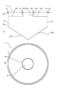
In the drawings, the reference numeral 1 indicates a net cage in accordance
with the
invention. The net cage 1 includes a net 2 forming a fish enclosure 3, first
floating
means 4 in a water surface 5 and a connection channel 6 projecting up from a
fish-
dismissing ceiling 22. The fish-dismissing ceiling 22 extends over the fish
enclosure 3.
The connection channel 6 projects up above the water surface 5. The net 2
includes a
side wall 24 and a bottom 26.
The connection channel 6 is attached to the ceiling 22 in an opening 28 in
such a way
that fish cannot swim out of the fish enclosure 3 between the jacket 62 of the
connec-
tion channel 6 and the ceiling 22. The connection channel 6 is formed with a
sufficient
cross-sectional area for fish in the fish enclosure 3 to be able to swim
spontaneously
to the water surface 5 and down again to the fish enclosure 3. The connection
channel
6 may have a cross section of, for example, 2 m, 3 m or larger.
CA 02853658 2014-04-25
WO 2013/066191
PCT/N02012/050213
8
The connection channel 6 is made up of an upper portion 64 which projects up
above
the water surface 5 and a submerged portion 66 which extends from the water
surface
to the fish-dismissing ceiling 22 as shown in figure 4. The upper portion 64
is sur-
rounded by a second floating means 42 in the water surface 5. The jacket 62 of
the
5 connection channel 6 may be constituted by one material or be assembled
from sev-
eral types of material. In a portion 65 from the water surface 5 down to a
depth which
is assessed as deep enough for toxic algae and/or parasitic crustaceous larvae
to stay
above this depth, the jacket 62 may be constituted by a watertight material.
In an
alternative embodiment, the portion 65 may be constituted by a plankton-
dismissing
lo cloth capable of water throughput, or a plankton-dismissing net capable
of water
throughput. Such a plankton cloth or plankton-dismissing net may have an
aperture of
303 rn. In a portion 67 of the submerged portion 66, the portion 67 extending
from
the fish-dismissing ceiling 22 to the portion 65, the jacket 62 may be
constituted by a
fish-dismissing net. In a further alternative embodiment, both the portion 65
and the
portion 67 may be constituted by a watertight material. This enables the
creation of a
downward water current within the connection channel 6 by supplying water to
the
connection channel 6. Such a water current will stimulate salmonoids to move
up-
wards in the connection channel 6 and up to the water surface 5.
The jacket 62 of the upper portion 64 of the connection channel 6, projecting
above
the water surface 5, is constituted in a lower portion 68 by a watertight
material. The
lower portion 68 forms a swash portion 68. The swash portion 68 may extend for
ex-
ample 1 metre above the water surface 5. In an alternative embodiment, the
swash
portion 68 may be constituted by a plankton-dismissing cloth or a plankton-
dismissing
net. The swash portion 68 extends so much above the water surface 5 that
undesired
plankton is prevented from being splashed or swashed into the connection
channel 6.
When a downward water current is created within the connection channel 6, the
por-
tion 68 is constituted by a watertight material. The water creating the
downward wa-
ter current in the connection channel 6, may be pumped up from a water depth
which
is counted as free from undesired plankton. The water depth may vary with the
sea-
sons and may be determined from, for example, water temperature and algal
blooms.
The upper portion 69 of the upper portion 64 of the connection channel 6 is
consti-
tuted by a jump net 69 of a kind known per se. The jump net 69 may constitute
part
of the jacket 62. In an alternative embodiment, the jump net 69 surrounds the
con-
nection channel 6 without constituting part of the jacket 62. In this
embodiment, the
jump net 69 is independently attached to the second floating means 42. The
second
floating means 42 may be constituted by one or more circular floating rings
having a
CA 02853658 2014-04-25
WO 2013/066191
PCT/N02012/050213
9
centre substantially coinciding with the vertical centre axis 8 of the
connection channel
6.
The net cage 1 may be provided with a so-called bird net 7 of a kind known per
se, to
prevent predatory birds from getting access to the fish in the net cage 1.
According to
the invention, the fish in the net cage 1 will be kept inside the fish
enclosure 3 by the
side wall 24, the bottom 26 and the fish-dismissing ceiling 22. Diving
predatory birds
will therefore be unable to penetrate into the fish enclosure 3. According to
the inven-
tion, it will therefore be sufficient to extend the bird net 7 over the
projecting upper
portion 64 of the connection channel 6.
In an alternative embodiment, the bird net 7 may be constituted by a net 7 of
a
smaller mesh size. The net 7 may be of the same type as the net constituting
the fish-
dismissing ceiling 22, or the side wall 24 or the bottom 26. This has the
advantage of
the entire connecting cannel 6 being submersible without the fish in the
enclosure 3
being able to swim out through the connection channel 6. De-icing of the upper
por-
is tion 64 of the connection channel 6 may be carried out by submerging the
entire con-
nection channel 6. The net 7 will also prevent the escape of fish from the
connection
channel 6 by large wave height, as the waves may wash over the jacket 62 of
the
connection channel 6.
Especially in large net cages 1 it may be advantageous to have more than one
connec-
tion channel 6. Figures 2A, B and figure 3B show alternative embodiments of
net
cages 1 with two connection channels 6. The person skilled in the art will
appreciate
that one net cage 1 may also be provided with more than two connection
channels 6.
The net cages 1 may be circular as shown in figures 1A, B and figures 2A, B,
or be
rectangular as shown in figures 3A, B. It is within the art to use the
invention on net
cages 1 of other geometries.
The fish-dismissing ceiling 22 may be attached internally to the side wall 24
in several
ways. At a desired depth, the side wall 24 may be provided with a line (not
shown)
which is sewn into the net meshes of the side wall 24. Such a line is known as
a so-
called belly band. This may be done on the netting of existing net cages 1 by
pulling
the netting up until the desired depth comes out of the water. The fish-
dismissing ceil-
ing 22 is provided with a reinforcing band (not shown) at its edges. Then,
along its
edges, the fish-dismissing ceiling 22 is sewn to the belly band in the side
wall 24. The
netting is finally submerged again and the fish-dismissing ceiling 22 will
position itself
at the desired depth and keep the fish within the net cage 1 below the fish-
dismissing
ceiling 22. An alternative method may be to provide the edge portion of the
fish-
CA 02853658 2014-04-25
WO 2013/066191
PCT/N02012/050213
dismissing ceiling 22 with a zip half (not shown) which complementarily fits a
zip half
(not shown) attached to the side wall 26. The zip half of the side wall 24 may
be at-
tached to a belly band.
The connection channel 6 may be attached to the fish-dismissing ceiling 22 in
the
5 same way as that described for how the fish-dismissing ceiling 22 may be
attached to
the side wall 24.
In an alternative embodiment, the fish enclosure 3 may be supported by lines 9
ex-
tending from the first floating means 4 to the side wall 24. In this
embodiment, which
is shown in figure 6, the enclosure 3 may be lowered to the desired depth
independ-
10 ently of the vertical extent of the side wall 24. The connection channel
6 is made long
enough.
The connection channel 6 may substantially be formed as a cylinder, as shown
in fig-
ures 1-4 and 6. Figures 5A, B show alternative embodiments of the connection
chan-
nel 6. The person skilled in the art will know that even other embodiments are
possi-
ble, and that the connection channel 6 may be formed with a cross section
other than
a substantially circular cross section. The connection channel 6 may be
assembled
from rigid panels or from a material in cloth form or from a material in cloth
form at-
tached to a framework. The connection channel 6 may be provided with one or
more
braces 63, 63' which give the connection channel 6 the desired cross-sectional
shape.
The brace 63 may be positioned on the inside of the connection channel 6, or
the
brace 63' may be positioned on the outside of the connection channel 63'. The
connec-
tion channel 6 is kept extended in the vertical direction by the second
floating means
42 and by attachment to the fish-dismissing ceiling 22. It is advantageous
that the
connection channel 6 may be shortened and lengthened along the axis 8 to
follow
wave movements on the water surface 5. This is achieved by the jacket 62 being
con-
stituted, in portions, by a material in cloth form which is kept extended by
braces 63,
63'. The braces 63, 63' may be annular. The brace 63 may extend helically
along the
inside of the jacket 62. The brace 63 may extend helically along the outside
of the
jacket 62.
In one embodiment, in which the swash portion 68 of the connection channel 6
and
the uppermost portion of the submerged portion 65 are constituted by a
watertight
material, the connection channel 6 may be used for bath-treatment of the fish
in the
enclosure 3. The watertight uppermost portion of the submerged portion 65 may
ex-
tend for example 0.5 m below the water surface 5 and the swash portion 68 may
ex-
tend for example 0.5 m above the water surface 5. The medicament is then
distrib-
CA 02853658 2014-04-25
WO 2013/066191
PCT/N02012/050213
11
uted in the water that is inside the connection channel 6. Such bath treatment
may be
necessary as some attacks by crustaceous parasites may occur in spite of the
fish be-
ing kept outside the part of the water column in which most of the crustaceous
para-
sites are found. Such bath treatment may also be relevant when fish are being
trans-
ferred to the fish enclosure 3 from net cages in which the fish have been
staying in the
entire water column. This has the advantage of enabling bath treatment to be
imple-
mented without work-demanding operations such as raising the netting and
putting
out a skirt around the enclosure 1. It also has the advantage of the fish
being exposed
to the medicament only for a short time, so that the concentration may be
increased
to subject the parasite to a therapeutic dose in a very short time. This has
further the
advantage of enabling much of the medicament to be pumped out of the
connection
channel 6 and collected instead of being spread to the surrounding
environment. Trials
have shown that it may be advantageous to lower the connection channel 6 com-
pletely below the water surface 5 so that the fish in the fish enclosure 3
will not have
access to the water surface for a period of 2 to 3 days. When the connection
channel 6
is raised again so that there is access to the water surface 5 inside the
connection
channel 6, the fish in the fish enclosure 3 will swim up into the connection
channel 6
within 1-3 hours to fill their swim bladders. This spontaneous roaming of
physosto-
mous fish may be utilized for a spontaneous bath treatment as described above.
Such
a spontaneous bath treatment will inflict little stress on the fish.
In this embodiment, gas may also be mixed into the water within the connection
channel 6, for example by injecting bubbling gas into the lower portion of the
connec-
tion channel. Such gas may be ozone to disinfect the inside of the connection
channel
6. Treating the inside of the connection channel 6 with ozone gas will also
prevent or
at least reduce fouling on the inside of the jacket 62. Ozone gas may also be
used to
reduce fouling on the outside of the jacket 62. The use of ozone gas in the
connection
channel 6 may also be used therapeutically to treat the fish in the fish
enclosure 3 of
infectious diseases on gills and skin.
The fish that are kept in the fish enclosure 3 may be fed in the usual way by
feed be-
ing spread across the water surface 5 within the first floating means 4. The
feed will
sink down the water column, passing the fish-dismissing ceiling 22, as this
may be
constituted by a net, in order then to be eaten by the fish in the enclosure
3. To entice
the fish into spontaneously swimming up into the connection channel 6, it may
be ad-
vantageous to distribute some of the feed, or all the feed, in the connection
channel 6.
CA 02853658 2014-04-25
WO 2013/066191
PCT/N02012/050213
12
A further alternative embodiment is shown in figures 7A, B. A hamster wheel 90
is
positioned in such a way that the centre of the hamster wheel 90 is concentric
with
the centre axis 8 of the connection channel. The hamster wheel 90 includes a
lower
floating ring 91 and an upper top ring 92. A plurality of uprights 93 extend
from the
lower floating ring 91 to the top ring 92 as it is known within the art. At
least one rib
94 projects down from the floating ring 91 along the connection channel 6. One
or
more of the ribs 94 may be positioned on the inside of the jacket 62. One or
more of
the ribs 94 may be positioned on the outside of the jacket 62. One rib 94 may
be a
vertical extension of one upright 93. The rib 94 may project down from the
floating
ring 91 to the ceiling 22. In addition to one or more ribs 94, the connection
channel 6
may be provided with one or more braces 63, 63' of the same type as that shown
in
figure 4. The braces 63, 63 may be formed as described in other embodiments in
the
above. It is advantageous that the ribs 94 substantially project down side by
side from
the floating ring 91. It may be advantageous that the number of ribs 94 is
four or
more. It may be advantageous that the number of ribs 94 is six or more. It may
be
advantageous that the number of ribs 94 is eight or more.
The rib 94 may be attached to the inner circumference of the floating ring 91.
Alterna-
tively, the rib 94 may be attached to the outer circumference of the floating
ring 91.
In a further alternative, the rib 94 may be attached to the submerged surface
of the
floating ring 91 between the inner and outer circumferences. In a further
alternative,
an upright 93 and a rib 94 may be constituted by a continuous element that has
been
passed through a bore (not shown) of the floating ring 91, In a further
alternative, an
upright 93 and a rib 94 may be constituted by a continuous element and the
floating
ring 91 is attached to the side surface of the continuous element.
A further alternative embodiment is shown in figure 8A, B. A tower 96 is
positioned in
such a way that the centre of the tower 96 is concentric with the centre axis
8 of the
connection channel. The tower 96 includes a lower floating ring 91' and an
upper top
ring 92' with a smaller diameter than the floating ring 91'. A plurality of
slanting up-
rights 93' extend from the lower floating ring 91' up to the top ring 92' as
it is known
within the art. At least one rib 94' projects down from the floating ring 91'
along the
connection channel 6. One or more of the ribs 94' may be positioned on the
inside of
the jacket 62. One or more of the ribs 94' may be positioned on the outside of
the
jacket 62. The rib 94' may project down from the floating ring 91 to the
ceiling 22. In
addition to one or more ribs 94', the connection channel 6 may be provided
with one
or more braces 63, 63' of the same type as that shown in figure 4. The braces
63, 63'
may be formed as described for other exemplary embodiments in the above.
CA 02853658 2014-04-25
WO 2013/066191
PCT/N02012/050213
13
The rib 94' may be attached to the inner circumference of the floating ring
91'. Alter-
natively, the rib 94' may be attached to the outer circumference of the
floating ring
91. In a further alternative, the rib 94 may be attached to the submerged
surface of
the floating ring 91' between the inner and outer circumferences. In a further
alterna-
tive, the floating ring 91' may be attached to the side surface of the rib
94'. It is ad-
vantageous that the ribs 94 substantially project down side by side from the
floating
ring. It may be advantageously that the number of ribs 94 is four or more. It
may be
advantageous that the number of ribs 94 is six or more. It may be advantageous
that
the number of ribs 94 is eight or more.
At least one of the ribs 94 of the embodiments may be tubular with an opening
in its
lower portion and an opening in its upper portion (not shown). The opening in
the up-
per portion faces in towards the connection channel 6. The rib 94 is provided
with a
pump (not shown) of a kind known per se, which is arranged to lift liquid
inside a pipe.
The pump may be a so-called mammoth pump which creates an upward flow of fluid
in a pipe by pumping a gas, for example air, into the lower end portion of the
pipe.
Water will flow from the lower end portion of the rib 94, up through the rib
94 and out
at the upper portion of the rib 94 into the connection channel 6. In the
connection
channel 6 a downward water flow will be created.