Note: Descriptions are shown in the official language in which they were submitted.
CA 02853740 2014-04-28
WO 2013/061094
PCT/GB2012/052689
1
IMPROVEMENT OF A COMBUSTION ENGINE
Field of the Invention
The invention relates to improvements in and relating to combustion engines
and in
particular, but not exclusively, to improvements in the combustion efficiency
of internal
combustion engines.
Background
The operation of an engine using more than one fuel is known. Many of these
systems
try reduce the overall fuel cost by utilising a cheaper secondary fuel to
displace the
usage of a relatively more expensive primary fuel. Systems of this type can
either be
retrofitted to an existing engine or supplied as an integral part of the
engine / vehicle by
the manufacturer. There are a large variety of systems produced for the
automotive
market, particularly the light and heavy goods market, where the fuel costs
comprise a
significant cost for operators.
There are generally two types of system typically used.
The first type of system works by introducing a secondary fuel in addition to
the primary
fuel. The quantity of primary fuel is generally unchanged. These are generally
known as
'addition' systems. The principle involved is that the introduction of the
secondary fuel
increases the power/torque of the engine and that an adaptation made either by
the
original engine control system or by the operator results in a net fuel cost
saving. Some
systems of this type also employ some crude forms of control in an attempt
reduce the
primary fuelling, typically by changing the inputs from sensor or modifying
torque or
speed control inputs.
There are several limitations of such addition systems. The amount of
secondary fuel
that can be introduced is limited by the ability of the engine to combust the
secondary
fuel, primarily due to a lack of oxygen, commonly known as "oxygen depletion"
and the
secondary fuel "quenching" the combustion of the primary fuel. Operation in
this mode
leads to poor fuel consumption and high emissions due to incomplete combustion
and
the pass through of un-burnt fuel products that exits the exhaust. The fuel
saving
generated is not guaranteed and can be negative as well as positive.
Deliberate over-
powering of an engine will cause it to operate outside of its normal
operational. This will
CA 02853740 2014-04-28
WO 2013/061094 PCT/GB2012/052689
2
have negative implications in terms of manufacturer's warranty, insurance
approvals,
safety certification and potential engine life.
The second type of system works by introducing a secondary fuel in addition to
a
reduced quantity of the primary fuel. These are commonly known as
'substitution'
systems. The principle involved is that both primary and secondary fuels are
directly
controlled and that both fuels when combusted simultaneously generate
approximately
the same power/torque as the original engine when operating only on the
primary fuel.
The percentage of the two fuels employed gives rise to a further distinction
between
systems of this substitution-type. Systems which use a higher proportion of
secondary
fuel to primary fuel where the primary fuel is diesel and the secondary fuel
is gaseous
are known as diesel ignition gas engines. Systems which use a lower proportion
of
secondary fuel to primary fuel where the primary fuel is diesel and the
secondary fuel is
gaseous retain their classification as diesel engines.
Both types of substitution system are characterised in that they require a
minimum of
proportion of approximately 25% of secondary fuel to be employed for the
system to be
commercially viable. As similar figure is necessary for addition systems to be
viable,
assuming that they can be made to operate in a favourable mode that generates
a net
fuel cost saving.
US 4,463,734 discloses a diesel engine in which increasing proportions of
liquefied
petroleum gas (LPG) are metered to the engine as power demand increases,
starting
from as little as 20% gas and increasing to about 80% gas, where the
percentage is
given in calorific value. US 4,641,625 discloses a range of gaseous fuel in a
liquid gas
mixture of between 0 and 95% gas. US-A-6026787 and US 2005/0205021 both
disclose dual fuel engines, but without specifying the proportions of the
fuels.
WO 2008/036999 is directed to a dual fuel system and a dual fuel system
assembly
where liquid LPG and diesel are mixed and then distributed via the common rail
to the
combustion chambers. WO 2010/121306 relates to fuel systems for diesel
engines. In
particular, the invention relates to a dual fuel supply system for a diesel
engine having
an indirect-injection system. US 5,408,957 discloses LPG (propane), natural
gas,
hydrogen gas, or the like, is continuously injected at substantially constant
pressure into
the air intake manifold, or air induction system, of a conventional internal
combustion
engine, the engine being electronically, or mechanically, controlled to adjust
the air to
liquid fuel mixture to a optimum value. US 5,370,097 discloses a dual fuel
control
CA 02853740 2014-04-28
WO 2013/061094 PCT/GB2012/052689
3
system for use with an internal combustion engine which controls the flow of
liquid fuel
alone or in combination with a gaseous fuel. US 2011/301826 discloses a
conventional
gasoline engine that is retrofitted to operate as a bi-fuel engine calibrated
to burn
hydrogen gas as a primary fuel and gasoline as a secondary fuel at various
acceptable
air fuel ratios while avoiding forbidden air fuel ratios. WO 99/30024 relates
to a method
for producing NOx reductants by injecting hydrocarbon into a diesel engine's
combustion
chamber during the expansion cycle.
WO 2009/115845 discloses the injection of a small amount of a secondary fuel
having
a shorter molecular structure than a primary fuel for achieving homogenous
combustion. The shorter molecular structure of the secondary fuel is used as
an
accelerant to accelerate the chemical process and a range of between 5%-25% of
the
secondary fuel is disclosed. Moreover, both the supply of the primary and the
secondary fuel are controlled.
Thus, existing dual-fuel systems have several limitations, such as requiring a
minimum
fraction of approximately 25% of secondary fuel and/or requiring that the ECU
or
primary fuel supply are controlled or adapted.
It is therefore desireable to overcome these limitations and/or produce an
even greater
improvement in fuel efficiency.
According to one aspect of the invention there is provided a method of
improving the
efficiency of a combustion engine, the method comprising: measuring a quantity
of a
primary fuel being supplied to the combustion engine; determining an operating
state of
the combustion engine; selecting a fuel mapping profile based on an operating
state of
the combustion engine; and determining from the fuel mapping profile an amount
of a
secondary fuel to be injected as a fraction of the measured quantity of the
primary fuel.
According to another aspect of the invention there is provided a combustion
engine
comprising: a first sensor for measuring a quantity of a primary fuel supplied
to the
combustion engine; a second sensor for determining an operating state of the
combustion engine; a controller selecting a fuel mapping profile based on an
operating
state of the combustion engine; and the controller determining from the fuel
mapping
profile an amount of a secondary fuel to be injected as a fraction of the
measured
quantity of the primary fuel.
CA 02853740 2014-04-28
WO 2013/061094
PCT/GB2012/052689
4
According to yet another aspect of the invention there is provided a kit for
retrofitting a
combustion engine designed to combust a primary fuel, the kit comprising: a
tank for
holding a secondary fuel; an injector for injecting secondary fuel into the
engine; a
controller configured to receive: a first input indicating the quantity of the
primary fuel
being supplied to the engine, and a second input indicating an operating state
of the
engine; and wherein the controller is configured to select a fuel mapping
profile based on
the operating state and to determine from the selected fuel mapping profile,
an amount
of a secondary fuel to be injected by the injector as fraction of the measured
quantity of
the primary fuel.
According to yet another aspect of the invention there is provided a
controller for
controlling an injection of a second fuel into an engine supplied with a
primary fuel, the
controller comprising: a first input for receiving an indication of the
quantity of the
primary fuel being supplied; a second input for receiving an indication of an
operating
state of the engine; a memory for storing a plurality of fuel mapping
profiles; a
processor for selecting one of the fuel mapping profiles based on the second
input and
determining an amount of the secondary fuel to be injected as a fraction of
the
measured quantity of the primary fuel.
According to yet another aspect of the invention there is provided a method of
improving
the efficiency of a combustion engine, the method comprising: measuring a
quantity of a
primary fuel supplied to the combustion engine; and injecting an amount of a
secondary
fuel based on a fraction of the measured quantity of the primary fuel, wherein
once a
threshold quantity of the primary fuel is exceeded, the fraction of secondary
fuel
decreases as the quantity of primary fuel increases.
According to yet another aspect of the invention there is provided a method of
improving
the fuel efficiency of an internal combustion engine, the method comprising:
measuring
a quantity of a primary fuel supplied to the internal combustion engine;
injecting an
amount of a secondary fuel based on a fraction of the measured quantity of the
primary
fuel, the primary fuel having a larger molecular structure than the secondary
fuel;
splitting the primary fuel into smaller molecules using the secondary fuel.
Preferably or optionally, wherein the step of splitting comprises: a first
splitting of the
secondary fuel to produce radicals by compressing air that is combined with
the
CA 02853740 2014-04-28
WO 2013/061094
PCT/GB2012/052689
secondary fuel; and a second splitting of the primary fuel by combining the
radicals with
the primary fuel.
According to another aspect of the invention there is provided a method of
improving the
5 fuel efficiency of an internal combustion engine, comprising the steps of
measuring the
quantity of a first fuel having a first molecular structure injected into a
combustion
chamber of the engine during a combustion cycle, and supplying to the
combustion
chamber a controlled proportional quantity of a second fuel of a shorter
molecular
structure, wherein the amount by calorific value of the second fuel injected
is limited to
the Minimum Fraction where significant enhancement of combustion begins and
the
Maximum Fraction where the inefficiency of combusting the second fuel (for an
engine
designed to combust first fuel) significantly counters the enhancement
effects.
According to yet another aspect of the invention there is provided a method of
improving
the fuel efficiency of an internal combustion engine, comprising the steps of
measuring
the quantity of a first fuel having a first molecular structure injected into
a combustion
chamber of the engine during a combustion cycle, and supplying to the
combustion
chamber a controlled proportional quantity of a second fuel of a shorter
molecular
structure, wherein the amount of the second fuel injected is limited so that
the mass of
the combined fuels injected into the engine for a given level of performance
is less than
the mass of the first fuel needed to achieve the same level of performance
when injected
alone.
According to yet another aspect of the invention there is provided a system
for
improving the fuel efficiency of an internal combustion engine, comprising
means for
connection to the fuel supply system of the engine, means for measuring the
quantity of
a first fuel having a first molecular structure injected into a combustion
chamber of the
engine during a combustion cycle, and means for supplying to the combustion
chamber
a controlled proportional quantity of a second fuel of a shorter molecular
structure,
wherein the system comprises: a microprocessor for receiving signals from the
measuring means and monitoring means; and wherein the microprocessor is
adapted to
calculate the quantity of the first fuel injected and produce and transmit a
resultant
signal to said means for supplying the second fuel.
According to one aspect of the invention there is provided method of improving
the fuel
efficiency of an internal combustion engine, the method comprising: measuring
a
quantity of a primary fuel supplied to the internal combustion engine; and
injecting an
CA 02853740 2014-04-28
WO 2013/061094
PCT/GB2012/052689
6
amount of a secondary fuel based on a fraction of less than 15% of the
measured
quantity of the primary fuel, the primary fuel having a larger molecular
structure than
the secondary fuel.
Brief Description of the Drawings
Embodiments of the invention shall now be described, by way of example only,
with
reference to the accompanying drawings in which:
Figure 1 shows an internal combustion engine according to an embodiment of the
present invention;
Figure 2 shows a kit that can be retrofitted to an existing engine according
to an
embodiment of the present invention;
Figure 3 shows the maximum fraction of the secondary fuel for different
operating
states of the engine;
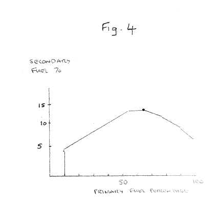
Figure 4 shows a fuel mapping profile for the "normal" or running mode of
operation;
Figure 5a shows a side view of a vehicle before a retrofit of the gas
controller
system;
Figure 5b shows a side view of a vehicle after a retrofit of the gas
controller
system according to one embodiment;
Figure 5c shows an opposite side view of a vehicle after a retrofit of the gas
controller system according to one embodiment;
Figure 6 shows the functionality of the gas controller according to an
embodiment
of the invention; and
Figure 7 shows the hardware of the gas controller according to an embodiment
of
the invention.
Detailed Description
CA 02853740 2014-04-28
WO 2013/061094 PCT/GB2012/052689
7
According to one embodiment, improved efficiency of an internal combustion
engine is
obtained without controlling and/or modifying the ECU, the main combustion
chamber or
the primary fuel supply of the engine. Instead, the quantity of primary fuel
(for example,
diesel) being supplied is measured and a controller is able to determine from
a pre-
determined fuel mapping profile, the optimal fractional amount of secondary
fuel (for
example, gas) that is to be injected.
In one embodiment, the fuel mapping profile determines the fraction of the
secondary
fuel to be injected as a function of the primary fuel being injected. The fuel
mapping
profile is based on maintaining the engine in an enhanced co-combustion mode
of
operation across the range of an engine's operation. In other words, just the
right
amount of secondary fuel (gas) needs to be injected to maintain the vehicle in
this
enhanced combustion mode across its range of operation.
According to an embodiment of operation, by optimising the burn (or combustion
process), it is possible to use less of the diesel, which results in greater
fuel efficiency.
The fuel mapping profile selected is therefore based on keeping the engine
operating in
this enhanced combustion mode of operation over its entire operating range,
which
results in greater fuel savings. An engine behaves differently under different
conditions.
A vehicle that is cruising at a steady speed will behave very differently to
one
accelerating under a heavy load. Therefore, a number of fuel mapping profiles
are
predetermined, each corresponding to a different state of the engine.
Figure 3 shows a graph indicating various engine states, "idle", "cruise",
"normal",
"other" and "fault". The "other" state might be a transient mode of operation
(heavy
acceleration or gear changing etc.). The "stop" state is effectively the same
as the "fault"
state since the gas system should be available for operation all of the time,
but can be
isolated.
According to an embodiment, a maximum fraction of the secondary fuel (as a
percentage of the primary fuel supplied) is determined for each of the
different engine
states. For example, in the "normal" state it can be seen that the maximum
fraction of
the secondary fuel supplied, as a percentage of the primary fuel, is 15%.
Thus, if the engine is determined as being in the "normal" state, a
corresponding fuel
mapping profile can be selected as is shown in Figure 4. The fuel mapping
profile has a
generally inverted V-shape. This means that initially the fraction of gas to
be supplied
CA 02853740 2014-04-28
WO 2013/061094 PCT/GB2012/052689
8
will increase as the supply of diesel increases. However, once a threshold
quantity of the
primary fuel has been reached, it has been found that the engine is maintained
in the
enhanced combustion mode by decreasing the fraction of gas as the diesel
increases.
Indeed, Figure 3 shows an example of a fuel mapping profile according to one
embodiment, in which it can be seen that the curve tapers off once a threshold
quantity
of around 65% of the primary fuel has been exceeded. In other words, the
profile shows
that initially the fraction of gas to be injected (as a percentage of diesel)
increases as the
supply of diesel increases, but once the supply of diesel exceeds a threshold
value, the
fraction of gas to be injected starts to decrease or taper off.
In contrast, conventional dual-fuel systems try control the supply of both the
primary
and second fuel (diesel and gas). Moreover, this is typically done by
employing a linear
(and/or proportional) relationship between the level of primary and secondary
fuels that
are introduced. Indeed, conventional wisdom would suggest that more diesel
requires
more gas.
However, according to an embodiment of the invention, it has been found that
once a
threshold value of diesel is exceeded, a more efficient burn is achieved by
decreasing the
amount of gas introduced as the amount of diesel increases. This tapering (of
the fuel
map profile) prevents oxygen depletion of the engine in that just the right
amount of
secondary fuel is supplied to keep the engine operating in the enhanced mode.
An embodiment of the invention controls only the supply of the secondary fuel,
relying
on the existing controller (ECU) to operate as it is designed to, i.e. to
control the supply
of the primary fuel (that the engine was designed for). The original ECU
monitors and
adjusts the primary fuel volume to compensate for how efficiently the fuel is
combusted.
By operating in co-combustion mode, in effect the same efficiency (or energy
given off)
can be achieved with less diesel, and the ECU will only notice that less
diesel is required.
It is found in an embodiment of the invention that this enhanced mode of
combustion
can be sustained with only a minimal fraction of gas being injected, i.e. < 15
% for all
engine states, and for some states, considerably lower (see Figure 3).
The fuel mapping profile of Figure 3 shows that the function can comprise both
linear
and non-linear portions. Moreover, some portions of the function can be
directly
proportional, while another portion can be inversely proportional.
CA 02853740 2014-04-28
WO 2013/061094
PCT/GB2012/052689
9
According to an embodiment of the invention, these fuel maps may be
established upon
start-up of the engine, in which an automatic self-calibration step is
performed. In an
alternative embodiment, these fuel maps can be predetermined based on
extensive tests
of different engine states in the laboratory. In another embodiment,
predetermined fuel
mapping profiles can be determined, but the self-calibration step can be used
to alter or
refine these predetermined maps over time as the response of the engine
changes.
In an embodiment, the fuel mapping profile can be selected by means of
measuring
particulate emissions. That is, by measuring the non-combusted emissions in
the
exhaust. In one embodiment, the fuel mapping profile will be determined by
taking into
account a measurement from a smoke opacity sensor that is located in the
exhaust of
the vehicle. In this way it is possible to determine the minimum amount of gas
necessary to achieve maximum translucency for any given diesel use and /or
rpm. It is
also possible from this measurement to determine the maximum fuel mapping
profile, i.e.
the maximum fraction of gas to be injected possible before the smoke (i.e.
particulate)
increases.
The state of the engine can be determined in various different ways as will
become clear.
For example, it is possible to use the primary fuel rail pressure (from an
existing engine
sensor) and the duration of the primary fuel injector control signal (an
output of the
original ECU).
In another embodiment, by taking into account the state of the engine (for
example by
measuring inputs such as the RPM and/or the particulate emissions), a more
precise fuel
mapping profile can be selected. Embodiments of the invention are therefore
able to
provide a more accurate fractional range of secondary fuel that is still
between 1-15%
of the measured quantity of the primary fuel, but where a fuel mapping profile
might
differ depending on whether a vehicle is cruising along or accelerating under
a heavy
load. In one embodiment, the exact fraction (or percentage) of this range, is
capable
of being more accurately determined by not only taking into account the
measured
quantity of the primary fuel but also the engine state and/or emissions. That
is, the
engine in an idle state will behave quite differently as to compared to when
the vehicle
is accelerating or under a heavy load. Embodiments of the invention are able
to take
these variables into account and being more accurate as to exactly where
within the
envelope, the fraction (or percentage of the primary fuel) lies. In effect,
the fuel
CA 02853740 2014-04-28
WO 2013/061094
PCT/GB2012/052689
mapping profiles act as a sort of multi-dimensional algorithm that is able to
take into
account other variables.
According to one embodiment, the enhanced co-combustion mode is achieved by a
5 "cracking" process, which fundamentally alters the burn at a chemical
level.
Specifically, The secondary fuel is used to crack the primary fuel such that
the primary
fuel is split into smaller molecules that are easier and more completely
combusted. This
results in the improved efficiency of an internal combustion engine.
10 Figure 1 shows an embodiment of the invention, in which an internal
combustion engine
has a turbocharger 106 located upstream of a combustion chamber 112. The
turbocharger has a rotating turbine (not shown) that sucks air into it to aid
in the
combustion process. In the embodiment shown, the gas is injected into the
turbo unit
106. This is then mixed with the air creating an even distribution of the
air/gas mix,
which then enters the combustion chamber 112 and is compressed. This
compression of
the air/gas mixture splits the short-chained gas into even shorter-chained
molecules (or
even atoms), known as radicals. The radicals are then present in the
combustion
chamber 112 and bind with the longer-chained diesel hydrocarbons, causing the
diesel to
split into shorter molecules that are more easily combusted.
Therefore, only a small amount of gas is needed to improve the combustion of
the diesel.
The gas is split into smaller components, which splits the diesel into smaller
components.
This splitting process encourages a chemical chain reaction to take place
throughout the
chamber which results in a more homogeneous fuel/air mix. In a spark ignition
engine,
the gas mixes easily with the air and pervades the interior of the engine's
combustion
chamber. Moreover it burns easily so that it, at least, is entirely combusted
and in doing
so ensures that all the fuel ignites also. At least, a greater majority of the
fuel is
combusted in both engine types. Accordingly, the efficiency of the engine is
enhanced.
The term "cracking" is broadly understood as a chemical process for the
splitting of
molecules. In the sense of fuels, different fuels have different molecular
structures,
some have more complex molecular structures or longer-chained hydrocarbons as
compared to others. Different fuels may contain different lengths of
hydrocarbon chains
or complexity of molecular structure. According to one embodiment the internal
combustion engine is designed for use with a first fuel, such as diesel.
Diesel is
constituted by relatively long-chained hydrocarbon molecules. Cracking enables
these
CA 02853740 2014-04-28
WO 2013/061094
PCT/GB2012/052689
11
long-chained hydrocarbon molecules to be split into shorter-chained
hydrocarbon
molecules that are more efficiently combusted.
Thus, according to an embodiment the fuel is cracked to improve the efficiency
of an
internal combustion engine. In one embodiment, this is achieved by ionisation
of the
gas in mixing it with air and compressing it to produce radicals, which in
turn crack the
longer diesel hydrocarbon-chains. The principle of cracking is specifically
applied by
injecting a small amount of a secondary fuel constituted from relatively
shorter-chained
hydrocarbons, which results in increased efficiency of an internal combustion
engine, for
example improved fuel efficiency, less emissions, etc. The amount of gas
injected is
carefully controlled based on the measured quantity of the diesel being used
by the
engine. More particularly, the exact amount of gas is based on a determined
fuel
mapping profile (envelope), which according to various embodiments also takes
into
account other variables such as the state of the engine and/or the particulate
emissions
in the exhaust.
According to an embodiment, cracking enables the secondary fuel to act as both
an
accelerant and a reagent (or reactant). Specifically, a reagent brings about a
chemical
reaction and/or is consumed in the course of the chemical reaction. The
radicals,
produced by the cracking, induce a chemical reaction by attaching to, and
breaking up,
the primary fuel into shorter-chained hydrocarbons. Moreover, the resulting
shorter-
chained hydrocarbons are more easily and more quickly combusted.
According to an embodiment, cracking in the sense of splitting molecules is
carried out
twice. The gas is cracked and then the diesel is cracked. More specifically,
the gas is
cracked during a compression phase of the engine cycle, which puts the gas
into the
physical condition necessary to crack the diesel by (producing radicals). That
is, the
produced radicals are then present within the air mass during the ignition and
combustion phase, splitting up the diesel molecules into smaller molecules
that are
more easily combusted. In this embodiment, the diesel cracking and
ignition/combustion
occur simultaneously, but the gas cracking precedes it.
Although enhancement can occur in the range up to 25%, according to a
preferred
embodiment maximum enhancement occurs in the range from about 1% up to 15%,
which are the lower limits and upper limits for reducing diesel particulate
emissions.
A conventional internal combustion engine comprises a piston that reciprocates
within a
cylinder and a crank mechanism for converting the reciprocating movement of
the piston
CA 02853740 2014-04-28
WO 2013/061094
PCT/GB2012/052689
12
into a rotational output. The operation and efficiency of an internal
combustion engine
depends on a great number of factors, including the type and mixture of fuel
used, the
compression ratio, the dimensions of the piston / cylinder, the valve timing,
the ignition
timing, the temperature and distribution of temperature within the combustion
chamber.
One of the main factors however, that determines the overall efficiency of the
engine is
the manner in which the fuel is burned, which is typified by the speed and
completeness
of the combustion process.
Relatively complex hydrocarbon fuels such as diesel have a molecular structure
which is
long and relatively slow to cornbust which prevents some of the hydrocarbons
from fully
burning. Moreover, these long-chain hydrocarbons have a tendency to coalesce,
preventing efficient mixing with air or oxygen during the combustion process.
Also, diesel burnt in an enclosed chamber that is externally cooled will tend
to ignite first
in the centre of the chamber and the ignition will then spread outwards
towards the
edges of the chamber. If the spread of this flame front is incomplete or
inefficient then
smoke and particulate matter will result which will be emitted during the
exhaust phase
of the engine.
A conventional 4-stroke engine has the following stages:
1. an intake stroke, in which air and primary fuel are drawn in,
2. a compression stroke, in which the air and primary fuel are compressed and
ignited,
3. a combustion stroke, in which the primary fuel combusts and the piston is
displaced.
4. an exhaust stroke, in which the un-combusted particulate is driven out the
exhaust.
In a conventional 4 stroke engine, combustion (burning of the fuel) occurs
during the
"ignition" or "power" stroke of the piston and in most engines the geometry of
the
engine fixes the displacement and acceleration of the piston during the power
stroke.
To maximise the efficiency of an engine it is important to burn as much of the
primary
fuel as possible during the power stroke. However, the chemistry and
thermodynamics of
combustion place practical limits on the maximum percentage of the fuel that
can
actually be combusted during the power stroke which generally leads to amount
of un-
combusted fuel remaining in the cylinder after the power stroke.
CA 02853740 2014-04-28
WO 2013/061094
PCT/GB2012/052689
13
Typically, a conventional heavy duty diesel engine combusts only up to 80% of
the fuel
present in the cylinder during the power stroke.
An embodiment of the invention aims to increase this percentage figure closer
to 100%,
by enhancing the combustion process.
The main factors that affect the proportion of the available fuel that can be
burnt include:
- The nature of the fuel itself. The combustion characteristics which
include the
cetane and octane rating.
- The dimension of the cylinder. The larger the cylinder volume the longer it
will take for the "flame front" to reach the boundaries of the cylinder, which
for large dimensions or slow flame fronts at high engine speeds may never
occur.
- The timing of the engine. The valve timing and the timing of the
initiation of
combustion will affect the proportion of fuel burnt. In one embodiment, the
engine efficiency is improved by controlling the homogeneity or uniformity of
the combustion process. If the source of ignition can be spread throughout
the combustion chamber then the combustion process will be less
compromised by flame front effects, or temperature variations in the
combustion cylinder.
These factors are equally applicable to rotary or turbine engines.
Figure 1 shows a basic embodiment of an internal combustion engine, but it
should be
appreciated that other embodiments and configurations are equally applicable.
For
example, in an alternative embodiment (not shown) the secondary gas is not
injected
into the turbocharger unit 106. Instead, in one embodiment there is a post-
turbo
injection unit (not shown). In another embodiment, the secondary fuel is
directly
injected into the combustion chamber 112
There may be other optional elements such as intercooler 108, which is shown
in Figure
1 as being located between the turbocharger 106 and the combustion chamber
112. The
combustion chamber 112 may comprise a variety of different configurations. For
example in a six-cylinder vehicle, the combustion chamber 112 may comprise six
corresponding manifold branches feeding into six corresponding pistons (not
shown).
The outlet of the combustion chamber is the exhaust 114 at which all the un-
combusted
particulate is emitted. The internal combustion engine will have an associated
tank 110
CA 02853740 2014-04-28
WO 2013/061094
PCT/GB2012/052689
14
for storing diesel and fuel lines for supplying diesel from the tank to the
cylinders in the
combustion chamber. The operation of the whole system is controlled by the ECU
(Engine Control Unit) 104, which monitors and activates the various components
of the
internal combustion system as is required. The links to the different engine
components
are not shown. Some of these links between the ECU 104 and the components are
optional depending on the vehicle configuration.
In the embodiment of Figure 1 there are no modifications or adaptations of the
ECU, the
main fuel supply or the combustion chamber. Instead, a separate gas controller
116 is
responsible for controlling the gas injected into the turbocharger 106. The
example in
Figure 1 shows a gas supply line 124 extending between the turbocharger 106
and a gas
tank 118. In the gas supply line 124, there is an injector 128 that can
control the
amount of gas that is injected into the air intake prior to the turbocharger
106. Control
of the injector 128 is achieved by the control output from the gas controller
116.
An embodiment of the invention provides a practical method for controlling,
monitoring
and delivering a secondary fuel to an engine. Where the proportion of
secondary fuel
employed is dependent on the amount of primary fuel employed and the
operational
state of the engine. The proportion of the secondary fuel employed is
generally less than
15% by volume of the primary fuel employed. The technique employed is that of
improvement or enhancement of the engine combustion which is managed in real
time
by the control system.
There is no overt control of the primary fuelling of the engine and any
adaptation to the
operation of the engine is affected primarily by the improvement in
combustion.
According to another embodiment of the invention, the following steps are
performed:
1. The volume of the primary fuel used in the engine is calculated in real
time.
2. The percentage of secondary fuel required is calculated based on the
operational
state of the engine
3. The volume of the secondary fuel required is calculated.
4. The injector opening times are calculated to deliver the required volume of
secondary fuel.
5. The secondary fuel is introduced into the engine to co-combust with the
primary
fuel in the engine cylinder.
CA 02853740 2014-04-28
WO 2013/061094
PCT/GB2012/052689
There are a variety of different ways for implementing each of these steps,
which are
now described in more detail.
For step 1, the volume of the primary fuel can be determined by measuring the
pressure
5 in the primary fuel rail and the opening time of the injector used to
introduce the
primary fuel into the engine. This applies to both common rail injectors and
unit injectors
which are the most common primary fuel delivery systems in use on vehicular
engines.
Additionally the temperature of the primary fuel may be used in the volume
calculation.
In an alternative embodiment the flow rate of the primary fuel is used in the
10 determination of the instantaneous volume of the primary fuel used. This
would be
applicable to steady state engines, commonly found in plant or marine
applications. In
yet an alternative embodiment the pressure in the primary fuel rail could be
determined
directly from the RPM of the engine. In yet an alternative embodiment the
pressure in
the primary fuel rail could be determined using data obtained from a data bus
connection
15 such as, but not limited to, a CAN bus. In yet an alternative embodiment
the opening
time of the primary fuel injector could be determined using data obtained from
a data
bus connection such as, but not limited to,a CAN bus. In yet an alternative
embodiment,
the amount of air being used in the combustion process could be calculated
using the
mass air flow, mass air pressure and wide band lambda sensors, either
individually or in
combination to determine the secondary fuel requirement. In yet an alternative
embodiment the instantaneous volume of primary fuel used could be determined
using a
data obtained from a data bus connection such as, but not limited to CAN bus.
In yet an
alternative implementation a measure of the exhaust particulates could be used
to
determine the optimum secondary fuel requirement.
For step 2, the operational state of the engine is determined by a number of
inputs,
including but not limited to; engine rpm (revolution per minute), primary fuel
rail
pressure, primary fuel injector opening time, temperature (engine water
temperature
and ambient outside temperature), orientation and motion of the vehicle. The
orientation
and motion of the vehicle would typically be determined by an accelerometer
that
operates in 3 axes, or a combination of tilt switches and speed sensors.
For step 3, in one embodiment the amount of secondary fuel required is
calculated based
on the amount of primary fuel used and the operational state of the engine.
In one embodiment, the operational state of the engine is used to set the
percentage of
the secondary fuel that is required, at between 0% and 15%. This can be done
via a
number of methods. In a first embodiment, a user-defined look-up table is used
CA 02853740 2014-04-28
WO 2013/061094
PCT/GB2012/052689
16
(commonly known as a map) to which a number of the engine inputs, defined
above (for
example engine rpm) are applied and the output of which is the percentage of
secondary
fuel required. There may be a plurality of maps for this purpose. In a second
embodiment, the percentage of secondary fuel can be set based on the
operational
states of the engine. This can include but is not limited to a fixed
percentage or a
percentage that is adjusted automatically as part of a calibration operation.
For step 4, in one embodiment the amount of secondary fuel required is
translated into
the required opening times for the injectors which control the delivery of the
secondary
fuel. The injectors can have different characteristics with respect to
different fuel flow
rates. They may also have different electrical or opening characteristics. The
translation
of the secondary fuel requirement into activation times for a plurality of
injectors shall
take into account the characteristics of the secondary fuel injectors, in
particular the
minimum opening or operating time, below which the delivery of a minimum
amount of
the secondary fuel cannot be guaranteed.
The relationship between the individual injector opening times and the
delivery of the
secondary fuel is determined experimentally by a calibration process. The
results of this
calibration procedure are stored in the non volatile memory in the system.
The injector opening times can be adjusted according to the pressure and
temperature
of the secondary fuel.
For step 5, according to one embodiment the injectors which control the
delivery of the
secondary fuel are then driven with an electrical signal designed to open and
close the
injector with a minimum of latency and also to minimise the steady state
electrical power
dissipation in the injector. Typically this would be achieved using a peak and
hold pulse
width modulation technique.
According to an embodiment, the gas controller 116 in Figure 1 is shown as
receiving
various control inputs. It is possible to receive inputs from the ECU 104, but
this is not
shown in the embodiment of Figure 1. It should be appreciated that a state of
the
engine can be obtained from the ECU in one embodiment. However, it should be
appreciated that the engine state can be monitored in other ways, which
require no input
from the ECU 804. In one embodiment, the gas controller 116 also has a control
input
shown from a measurement sensor 126 for determining the quantity of diesel
fuel is
being used or supplied to the engine in real-time. However, other embodiments
describe
CA 02853740 2014-04-28
WO 2013/061094
PCT/GB2012/052689
17
different ways, both direct and indirect, in which the diesel fuel can be
measured and/or
determined as has been described above. In one embodiment, the gas controller
116 is
implemented using a microprocessor for executing a computer program or
algorithm
stored in memory of the controller.
The algorithms which control the operation of the system, for example stored
in the
memory of the gas controller 116 in Figure 1, can be implemented in software
(SW),
firmware (FW) or a combination of both.
A state machine consisting of a minimum of five operational engine states
shall be used
to control the operation of the system, as follows;
= Stop ¨ the system is powered but the engine is not operating
= Idle - the vehicle is stationary and the engine is idling (no load on the
engine)
= Cruise ¨ the vehicle is operating at steady state conditions
= Normal/Running ¨ the vehicle is operating but not yet satisfying the
cruise
or idle requirements.
= Fault ¨ an operational error has been detected resulting in the shut down
of the system.
During the cruise and Idle states the system can perform automatic calibration
operations, which can include selection of a fixed percentage, proportion or
volume of
the secondary fuel to be delivered. Whilst in the stop state the system
performs built in
test (BIT) and diagnostics operations. Whilst in the running state the system
operates
normally. Whilst in the fault state the operation of the system is inhibited.
This is
characterised by the system being stopped in a safe state with the secondary
fuel
delivery system disabled.
The transition between the states of the state machine shall be controlled by
the
operational state of the vehicle, the engine and the system. In an alternative
embodiment data obtained from a data bus such as CAN could also be used to
provide
some or all of this information.
Specifically the system shall perform continuous monitoring in all states to
determine
correct operation of the entire system and the original engine. Additionally
the control
algorithms shall autonomously record any parameters derived during automatic
CA 02853740 2014-04-28
WO 2013/061094
PCT/GB2012/052689
18
calibration in a non-volatile memory, for example stored in the gas controller
116 (but
not shown).
The idle state shall be determined primarily, but not exclusively, by a
combination of the
rpm of the engine, the motion of the vehicle and the volume of primary fuel
used for a
vehicular application. The entry and exit from the idle state shall be
controlled by a
series of test on the primary inputs which shall include range and
persistency.
The cruise state shall be determined primarily but not exclusively by a
combination of
the rpm of the engine, the motion of the vehicle and the volume of primary
fuel used for
a vehicular application. The entry and exit from the cruise state shall be
controlled by a
series of tests on the primary inputs which shall include range and
persistency. The
cruise state may additionally use a speed input sensor. The entry into the
cruise state is
not however limited to a particular speed.
In a further embodiment, the system is able to perform an automatic self-
calibration on
start-up, for tuning the algorithm (executed in the gas controller 116) so
that the
minimum amount of secondary fuel is used that is necessary to generate the
maximum
combustion enhancement effect. This results in maximum performance, either in
terms
of net fuel economy, emissions or a combination of both.
The automatic calibration can be implemented using feedback information
obtained from
the engine sensors or data bus, or alternatively from dedicated instruments
(e.g. lambda
sensors, exhaust opacity sensors, temperature sensors). For example, a laser
sensor
can be inserted into the exhaust pipe of a vehicle to detect the quantity of
particulate
emissions. This signal is then feedback to the gas controller 116, and the
algorithm, can
adjust the level of secondary fuel injected accordingly ¨ if indeed
particulate emissions
are the variable to be controlled.
Typically an improved fuel economy corresponds with a reduction in particulate
emissions, since the fuel is being combusted more efficiently. However, in one
embodiment it may be that the user (or driver) is able to select one control
variable to
be paramount over the others. For example, an eco-sensitive driver might
prefer to
make the control of particulate emissions paramount, and can do this by
selecting an eco
option, which the algorithm in the gas controller 116 would interpret
accordingly. In an
alternative embodiment, another driver may prefer to minimise fuel costs and
therefore
CA 02853740 2014-04-28
WO 2013/061094
PCT/GB2012/052689
19
by selecting such an option, the algorithm in the controller would make the
control of
fuel efficiency paramount.
Although Figure 1 shows a separate gas controller 116, which operates
independently of
the ECU 104, it may be that the functionality of the gas controller is
incorporated into, or
designed to cooperate with, the ECU of the existing engine in an alternative
embodiment. Indeed in yet a further embodiment, an ECU may be to replace an
existing
ECU in being equipped with the gas controller functionality.
The gas controller 116 can be implemented in, and interface with the engine,
in various
ways. The interfaces can be either analogue or digital or data bus (e.g. CAN)
based. The
gas controller can be either a single unit, or a number of units depending on
the engine
type and application. It is envisaged that multiple units will require some
form of data or
network connection to allow them to operate collectively and possible operate
in a
master ¨ slave configuration. In another embodiment, the gas controller
functionality
may also be implemented in part or in total in the ECU which is used to
control the
primary fuel to the engine. This could be using spare capacity in the original
engine ECU
104, or by the use of a replacement ECU designed to control both primary and
secondary
fuels.
In one embodiment, the gas controller must also be operatively connected to
the control
and delivery system for the secondary fuel. The gas controller can also be
connected to
subsystems which are not directly associated with the engine. Typically this
would
include elements of the chassis control system or the exhaust and emissions
systems,
which would include any exhaust after treatment.
In another embodiment, the gas controller shall provide the software (SW) and
firmware
(FW) resources necessary to implement the control system. Typically this would
comprise a microprocessor for the SW and field programmable gate array (FPGA)
for the
FW. It is possible to implement the required functionality using SW or FW
alone, or by a
combination of both. It is also possible to implement the system using a
microprocessor
or a FPGA individually. The FPGA is capable of running both SW and FW using a
soft
core, or embedded microprocessor.
The gas controller shall provide a number of external communications
interfaces. These
can include Universal Serial Bus (USB - both Host and Device), Ethernet, RS232
and
Controller Area Network (CAN). These interfaces provide the capability for the
gas
CA 02853740 2014-04-28
WO 2013/061094
PCT/GB2012/052689
controller to operate in a network environment or connect to peripheral
components,
such as modems, nnaptop computers, or mass storage devices.
The gas controller shall implement the necessary circuitry to interface with
the engine
5 and the secondary fuel gas delivery system. This shall primarily be
provided using HW
components located on an electronic circuit board, but shall also include FW
or SW
support as required.
The circuits which interface with the engine shall be designed to provide
either galvanic
10 isolation, or if this is not possible, designed to present minimum
electrical disturbance to
the existing original circuit to which it is connected. This is to ensure that
the connection
is a far as possible undetectable by the original circuit under normal
operating
conditions. The circuit elements which control the energetic parts of the
secondary fuel
delivery system shall be designed so that a single fault does not result in
the activation
15 of any part of the secondary fuel delivery system that could present a
potential hazard.
Under normal operation conditions the secondary fuel delivery system shall be
monitored
to ensure that it is operating correctly. If a fault is detected then a fault
code is reported
and stored in non volatile memory. Dependent on the severity of the fault
code,
20 operation of the secondary fuel system can be disabled and not be re-
enabled until the
fault is rectified. For example, by activating a safety shut-off valves shown
in Figure 2,
as well be described in more detail below.
According to one embodiment, the electronic circuit board shall contain
dedicated non-
volatile memory. This shall be used for storing information such as hardware
serial
numbers, test results and fault codes and details of the application. The
memory can be
accessed and programmed using external test equipment which does not require
the
ECU to be powered. The ECU may incorporate techniques to prevent unauthorised
access
to the SW and FW programming, calibration and map data. The design of the ECU,
electronic circuit board, FW, SW and wiring harness may incorporate techniques
to
prevent reverse engineering of the product based on observation of the inputs
and
outputs. The design of the ECU may incorporate a number of monitoring
functions (e.g.
watchdogs) to check for incorrect operation of either the FW or the SW, the
result of
which will result in a reset of the affected sub-system.
The gas controller can be physically implemented in different ways. In one
embodiment,
the gas controller is sealed against water, dust and other contaminants. The
ECU shall
CA 02853740 2014-04-28
WO 2013/061094
PCT/GB2012/052689
21
use a sealed connector system. Ideally this will be a single connector. The
electronic
circuit board shall have a thermal path via the enclosure to prevent power
dissipated in
the unit from causing an excessive increase in temperature of the electronic
components.
The electronic circuit board and enclosure shall be designed to minimise
Electromagnetic
Emissions (EMI). The electronic circuit board and enclosure shall be designed
to
minimise Electromagnetic susceptibility. The ECU is designed to be compatible
with
mounting in an engine bay, or engine room.
Embodiments of the gas controller can be adapted for use with various
applications. For
example, the gas controller is capable of integration with a global
positioning system
(GPS) receiver. The system shall be capable of two way communications via a
radio
frequency (RF) modem (e.g. 3G or GPRS). This shall include the facility to
enable or
disable the system via this connection. This facility can provide telemetry
information
about the location and operation of the system. It can also be used to enable
the system
remotely. This provides protection against theft of the system and
additionally provides a
method of implementing and policing a pay per use, or lease-based commercial
model.
In another embodiment, the controller system is capable of integration with an
application programme running on a computer based system. This application
would
provide control and management for non vehicle applications (e.g. industrial
or marine).
The system can be customised for the majority of all envisaged applications
where
necessary by changes to the wiring harness, SW and FW only. It shall be
possible to re-
programme the unit SW and FW via the external connector. Each ECU shall be
programmed with a unique serial number. Each ECU shall be programmed with
sufficient
details to identify the application. For vehicle applications this could
include, engine,
chassis or registration number. This information may be obtained automatically
(e.g. via
CAN) where such facilities exist. The ECU shall implement an OBDII compliant
diagnostics and maintenance interface.
Figure 2 shows a kit that can be retrofitted to an existing engine according
to an
embodiment of the present invention.
The kit comprises a gas controller 116 that controls the injectors 128 (via a
control line
238) for supplying a quantity of gas from the gas tank 118 to the existing
internal
combustion supply line 124. Thus, this kit is intended to be bolted onto an
existing
internal combustion engine.
CA 02853740 2014-04-28
WO 2013/061094
PCT/GB2012/052689
22
The kit shown in the embodiment of Figure 2 has further optional elements
located
between the gas tank 118 and the injector 128. For example, a first pressure
and
temperature sensor 220, two electrical gas valves 224 and 230 able to perform
as a
solenoid or electrical shut-off, a vapouriser 226 capable of performing a gas
regulation
function and attached to a temperature sensor 228, a second pressure sensor
232 and a
manual gas valve for providing a mechanical shut-off function. The gas tank
may be
equipped with a float 240. The, electrical and mechanical valves may be
installed for
safety reasons to enable the gas supply to be shut-off in the event of a fault
mode or
otherwise.
In another embodiment, the gas controller 116 is configured to have a first
input from a
diesel injector, a second input from a rail pressure sensor and a third input
from a cam
sensor (for giving the RPM of the engine at any point in time). It will be
appreciated that
other inputs are also possible and are used by the gas controller 116 to
determine the
envelope (or fuel map profile), which in turn will determine the fraction (or
percentage)
of gas that will be supplied to the engine.
The kit can be retrofitted to a conventional internal combustion with no
modifications
to the ECU, the combustion chamber or control of the connections supplying it.
Whereas many conventional systems describe controlling the quantity of primary
fuel,
embodiments of the inventions are concerned with controlling the quantity of
the
secondary fuel based on a measured fractional quantity of the primary fuel.
Thus, the
system is able to react, rather than invasively control the behaviour of the
engine. The
ECU of the vehicle will act as per normal, except that the engine will just
achieve a
more efficient burn.
Figure 5a-5c show examples of a vehicle before and after a retrofitting
operation
according to an embodiment of the invention. More specifically, Figure 5a
shows a side
view of a vehicle before a retrofit of the gas controller system. In Figure 5a
is shown a
side view in which air tanks and a battery pack are fitted to a left hand side
of the
undercarriage of a truck. In figure 5b, after the retrofit, the air tanks have
been moved
inside the chassis of the truck and have been replaced by a gas tank (i.e.
secondary fuel
supply). In figure 5c, after the retrofit, and when viewed from the opposite
side, the
vehicle shows gas flowing from the gas tank through a gas solenoid (performing
a
similar function to the gas valves 224 and 230 in Figure 2) and a gas
regulator
(performing a similar function to the gas vapouriser 226 of Figure 2).
CA 02853740 2014-04-28
WO 2013/061094
PCT/GB2012/052689
23
Figure 6 shows an example of a functional (or software) implementation of the
functionality of the gas controller 116. Figure 6 shows a scheduler 610 or
operating
system for synchronising and scheduling of periodic operations. Also
responsible for
dealing with asynchronous inputs such as interrupts and internal error
detection. A
communications handler 620 provides the functionality for enabling the gas
controller
to connect with various communication interfaces and protocols. It is
responsible for
driving all communications interfaces, external and internal. Memory interface
630
provides various types of memory functionality and is responsible for
interfacing with
all memory resources, both internal and external to the processor. The
initialisation
functionality 650 is responsible for the SW operation immediately following
power up.
The processor performs a self test and then loads the operational SW from
memory. It
also loads the FPGA and then configures it with the default settings prior to
operation.
. The operations functionality 640 is responsible for running the algorithms
associated
with the dual fuel application. It is also able to select and execute the
relevant fuel
mapping profile based on these inputs to determine which outputs to activate
for
controlling the fraction of secondary fuel to be injected.
Figure 7 shows an example of the internal electronic architecture of the gas
controller
116. This shows the internal electronic architecture of the controller. The
processor is a
stand alone device. It is responsible for all of the external communications
interfaces and
supervisory functions. It communicates with an FPGA via a memory mapped
interface.
The FPGA is responsible for all real time functions. Both devices are required
to be
operation for the gas system to be activated. A microprocessor 720 is arranged
to
connect to various I/O interfaces (ETHERNET, USB, RS232, etc), sensors such as
a 3-
axis accelerometer 730 for determining the vehicle orientation and also other
ICs, for
example an FPGA 740, monitoring circuits 750 and drive circuits 760. The FPGA
740 is
connected to an EEPROM device and there is a JTAG integrated circuit for
allowing
testing of the board.
It should be appreciated that the functionality and components of Figures 6
and 7 are
standard in the industry and that other configurations, which are able to
implement
embodiments of the invention, are also possible.
In summary, according to an embodiment, a primary fuel consisting of
relatively long
chain hydrocarbon molecules is designed to be combusted in the cylinder of an
internal
combustion engine. A secondary fuel is able to act as an accelerant, reagent,
reactant
or catalyst and which is able to co-combust such that when it is introduced
into the
CA 02853740 2014-04-28
WO 2013/061094
PCT/GB2012/052689
24
engine cylinder there is an improvement in the efficiency of the combustion
process and
hence the efficiency of the engine. According to this embodiment, the
simultaneous
combustion of both primary and secondary fuels causes the engine to operate
with
greater efficiency than if the fuels had been combusted individually.
This enhanced combustion effect, or combustion improvement can be attributed
to the
addition of the secondary fuel causing more complete combustion of the primary
fuel
and also faster combustion of the primary fuel. This is characterised by
greater engine
efficiency and lower emission of particulates. Such effects are brought about
in one
embodiment by splitting the long chain hydrocarbon molecules of the primary
fuel into
smaller chain hydrocarbon molecules (commonly known as cracking), ionisation
of the
fuel air mixture in the engine cylinder, increasing the speed and spread of
the flame
front when combustion occurs and more favourable distribution of the fuel air
mixture in
the engine cylinder. In a preferred embodiment, the ratio of the secondary
fuel is less
than 15% of the primary fuel by volume when adjusted for calorific value.
According to an embodiment, a more complete combustion of the primary
hydrocarbon
fuel is encouraged by introducing a secondary fuel, or a plurality of fuels,
to act both as
an accelerant and a reagent to create a more homogenous or uniform combustion,
resulting in increased efficiency. In an embodiment, increasing the efficiency
of an
engine means that better fuel economy and/or greater power is available while
at the
same time improving the emissions standard of the engine by the introduction
of a
secondary fuel. According to another embodiment, there is provided a
convenient
method of delivery and control of a secondary fuel so that both primary and
secondary
fuels may be combusted simultaneously. According to another embodiment, there
is
provided a convenient method of delivery and control of a secondary fuel,
where the
secondary fuel is in the gaseous state when introduced into the engine.
According to
another embodiment, there is provided a secondary fuel delivery and control
system that
can be easily retrofitted to existing engines to convert them from operating
on a single
fuel to a plurality of fuels without extensive modification to the engine or
its control
system. According to another embodiment, there is provided a secondary fuel
delivery
and control system that can be incorporated by engine suppliers or vehicle
manufacturers to facilitate operation with a plurality of fuels without the
necessity to re-
map or re-calibrate the original engine management system.