Note: Descriptions are shown in the official language in which they were submitted.
CA 02853773 2014-05-30
SUSPENSION SYSTEM FOR MOTOR VEHICLES
FIELD OF THE INVENTION
The present invention is related to an axle suspension for wheeled motor
vehicles.
SUMMARY OF THE INVENTION
The present invention relates vehicle suspension systems, and more
particularly to
axle stabilizing systems.
BACKGROUND OF THE INVENTION
Truck suspension systems provide isolation of passengers and cargo from road
shock
while keeping the vehicle stable and preserving operator control. Generally,
these
objectives are met using various combinations of springs, motion dampening
devices and
auxiliary axle positioning elements.
The central element of any suspension system is the spring and there are many
different types of suspension systems. The basic types of suspension systems
used on trucks
include leaf spring systems, equalizing beam systems, torsion bar systems and
air spring
systems. Hybrid combinations of these are also used.
Leaf spring based systems are relatively popular and have been applied to both
steering and non steering axles as well as driven and non driven axles. In an
air based
system, air bellows known as convoluted air springs are positioned with
respect to an axle
vehicle frame to support the frame from the axle. Air spring systems are known
to provide
excellent load and vibration isolation compared to traditional leaf spring
systems. Air springs
usually have a lower deflection rate than a leaf spring exerting the same
force giving the
system greater capacity for absorbing shocks for a given displacement between
the axle and
the frame. Air spring pressure can also be adjusted to compensate for vehicle
load changes
- 1 -
CA 02853773 2014-05-30
by adding air to or exhausting air from the spring.
One weakness of air spring suspension systems is that they require more
auxiliary
stabilization to maintain the proper location and attitude of the axle with
respect to the
vehicle and to prevent excessive vehicle roll. Absent stabilization, air
springs can extend to
their maximum lengths or widths in the direction of least resistance and can
cause an
unevenly loaded vehicle to tip over to one side. Full leaf springs do not
suffer from this
disadvantage.
SUMMARY OF THE INVENTION
It is an object of the present invention to provide a stabilization
arrangement for air
spring based suspension systems.
BRIEF DESCRIPTION OF THE DRAWINGS
Having thus generally described the invention, reference will be made to the
accompanying drawings illustrating an embodiment thereof, in which:
Figure 1 is a perspective view of one side of a suspension system illustrating
the
present invention;
Figure 2 is a side elevational view thereof;
=
Figure 3 is a top perspective view thereof;
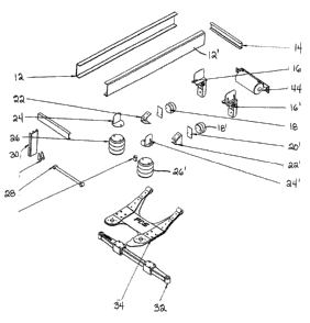
Figure 4 is an exploded view of the components forming a portion of the
suspension
system;
Figure 5 is an exploded view of a portion of the suspension system;
Figure 6 is a perspective view of a portion of the suspension system; and
Figure 7 is a perspective view illustrating both sides of the suspension
system.
- 2 -
CA 02853773 2014-05-30
DETAILED DESCRIPTION OF THE INVENTION
Referring to the drawings in greater detail and by reference characters
thereto, there is
illustrated a suspension system which is generally designated by reference
numeral 10.
Referring initially to Figure 4 which illustrates the components in an
exploded view,
there is provided a pair of frame members 12, 12'. A connecting member 14
extends
therebetween. Brackets 16, 16' are provided for connecting double convoluted
air springs 18,
18'. Bracket components 20, 20', 22, 22' and 24, 24' are then utilized for
connecting to a main
connecting plate 34 which will be described hereinbelow.
The air suspension includes a pair of triple convoluted air springs 26, 26'.
The air
springs are connected to connecting plate 34 and to frame members 12, 12'. As
shown, a
reinforcing bar 28 may extend transversely and be secured at one end by a rear
attachment 30.
Connecting plate 34 includes a base center portion 36 which has extensions 38,
38'.
Reinforcing legs 40, 40' ere secured to base center portion 36 while
connecting arms 42 are
provided. Connecting arms 42 can act as bushings.
In the illustrated embodiment, an air tag assembly 44 is provided.
It will be understood that changes and modifications may be made to the above
described embodiment without departing from the spirit and scope of the
invention. The
various components will be made of suitable material and in the case of
connecting plate 34,
material of an adequate thickness (between 1/4 inch and one inch) may be
utilized for each
portion thereof including the reinforcing legs 40, 40' and connecting arms 42.
-3 -
