Note: Descriptions are shown in the official language in which they were submitted.
CA 02854384 2014-06-16
Wind turbine blade with extended shell section
Field of the Invention
The present invention relates to a wind turbine comprising:
- a wind turbine tower having a top;
- a nacelle coupled to the top of the wind turbine tower, e.g. via a yaw
system;
- a rotor hub rotatably mounted to the nacelle;
- one or more wind turbine blades having a tip end located in the opposite end
of a
blade root configured to be mounted to the rotor hub, where the wind turbine
blade
comprises a pressure side connected to a suction side via a leading edge,
wherein the
wind turbine blade further comprises a first shell part having a first
trailing edge con-
nected to a first inner surface facing a second shell part, wherein the second
shell part
has a second trailing edge connected to a second inner surface facing the
first shell
part, wherein one of the two shell parts comprises an extended shell section
where the
trailing edge of the other shell part is coupled to the inner surface of that
shell part,
e.g. via a glue line.
The present invention also relates to a manufacturing method for a wind
turbine blade
where the method comprises the steps of:
- arranging a first set of layers in a first mould, where the layers form a
laminate defin-
ing a first shell part comprising a first inner surface connected to a first
outer surface
via a first and a second edge;
- arranging a second set of layers in a second mould, where the layers form a
laminate
defining a second shell part comprising a second inner surface connected to a
second
outer surface via a third and a fourth edge;
- infusing a resin, e.g. epoxy, into the laminates using an external infusion
system, e.g.
a vacuum infusion system, and curing the infused laminates, and removing the
exter-
nal infusion system.
Background of the Invention
The development of more cost-effective wind turbines means that the size and
height
of wind turbines today have increased. The size of wind turbine blades today
has also
increased which in turn also increases the production costs as the design of
an effec-
CA 02854384 2014-06-16
2
tive blade becomes more and more difficult. Therefore, there is a need for
improving
the aerodynamic shape and structural strength of wind turbine blades, as well
as opti-
mising the production of such blades.
Wind turbine blades typically comprise two shell parts which are reinforced by
using
internal reinforcement structures. Shear webs are most commonly used for this.
The
two shell parts are typically formed in separate moulds where load carrying
members,
such as spar caps, are integrated into the shell parts either as pre-made
parts or formed
during the shell layup process. When combining the two shell parts in a gluing
pro-
cess, the shear webs are added in between and glued and cured in the same
step. The
shape and internal structure of a wind turbine blade is generally designed so
that the
resulting turbine has a low cost of energy in a particular target market (wind
range and
environmental requirements), which makes the design a trade-off between power
pro-
duction, structural mass and cost, induced loads, noise and transport
considerations.
US 2007/0098561 A1 discloses a wind turbine blade having an upper shell part
and a
lower shell part where the trailing edge of the lower shell part is placed in
a retracted
position and glued to the inner surface of the upper shell part. The purpose
of this con-
figuration is to reduce the noise generated at the trailing edge which is
achieved by
retracting the trailing edge of the lower shell part relative to that of the
upper shell part
so the trailing edge thickness of the blade profile is defined only by the
laminate
thickness of the upper shell part. This extended trailing edge forms a thin
and narrow
profile having a width of no more than a few centimetres and a thickness of
less than a
few millimetres. The reduced trailing edge thickness is designed to reduce
noise, but
the limited width of the region will make it too stiff to significantly deform
under
loading, hence it should have a limited effect on the lift coefficient of the
blade pro-
file.
US 2011/0018282 Al discloses a similar solution in which the wind turbine
blade has
an integrated extended shell part with a serrated profile specially optimized
for noise
reduction. This also forms a stiff narrow profile having a limited effect of
the lift coef-
ficient as mentioned above.
CA 02854384 2015-10-06
3
It is known to attach a trailing edge extender in the form of a tape to the
wind turbine
blade, where the profile of this trailing edge extender is designed to reduce
noise. US
2012/0134817 Al discloses such a tape that is mounted to the trailing edge on
site. The
tape is so flexible that it has no capacity to redirect the air flow passing
over the blade,
and hence it has no impact on the lift coefficient of the blade profile.
Another solution is to arrange one or more active control flaps or DTEF in the
trailing
edge where the operation of these flaps is controlled by a control system
integrated into
the wind turbine blade or the nacelle; such a solution is known from Risoe DTU
and
WO 2008/131800 A1. Such systems are shown to have significant potential to
reduce
wind blade and wind turbine loads. However, such a system requires flaps or
deformable elements to be incorporated into the trailing edge of a wind
turbine blade,
and also sensors and actuators controlling the flaps or deformable elements to
be
integrated into the blade profile. This adds to the complexity of the
structure making it
more fragile and susceptible to dirt, lightning damage and moisture.
Furthermore, such
flaps or trailing edge require a separate active control system which in turn
increase the
production costs.
DE 19580147 B3 discloses a trailing edge element glued to the trailing edges
of the
two aerodynamic shell parts wherein the trailing edge element is made of an
elastomeric material capable of deforming due to the pressure difference
between the
pressure side and the suction side.
Object of the Invention
An object of this invention is to provide a wind turbine blade with improved
blade
profile characteristics.
An object of this invention is to provide a wind turbine blade with integrated
passive
load alleviation functionality.
An object of this invention is to provide a manufacturing process for a wind
turbine
blade with integrated passive load alleviation functionality that does not add
steps to
the manufacturing process or components to the wind turbine blade.
CA 02854384 2015-10-06
3a
Summary of the Invention
The present invention provides a wind turbine characterised in that
- the extended shell section is configured as a flexible shell section for
load reduction
where the first trailing edge is configured to move from a first position to a
second
position in a direction towards the suction side relative to the first leading
edge when
an incoming wind is acting on the pressure side of the wind turbine blade, and
CA 02854384 2014-06-16
4
- wherein the chord of the wind turbine blade has a relative length of 1 and
the ex-
tended shell section has a relative width of at least 0.10.
This provides a wind turbine blade with an improved blade profile where the
extended
shell section defines the trailing edge of the blade profile. The extended
shell section
allows the lift of the wind turbine blade to be optimised since it provides an
extended
trailing edge that is wider than the traditional trailing edge disclosed in US
2007/0098561 A1. The extended shell section has a configuration which enables
it to
flex or move in response to changes in the air flow velocity. The term
"flexible" is
defined as a shell section having a free end defining the trailing edge of the
wind tur-
bine blade which is able to flex or move relative to the leading edge of the
wind tur-
bine blade. The movement may be defined as the angular displacement between
the
chord in a first position and in a second position and/or as a reduction in
the maximum
distance between the mean camber line and the chord. The chord is defined as
the line
that extends through the leading edge and the outermost trailing edge of the
wind tur-
bine blade. In case of a flat-back profile with non-zero trailing edge
thickness, the
trailing edge point is defined as the middle of the trailing edge.
This allows the free end, i.e. the outermost trailing edge, to flex in a
substantially radi-
al direction relative to the fixed end, i.e. the retracted trailing edge. The
flexing in-
creases as the angle of attack increases. This means that an increased
aerodynamic
load, e.g. in the event of a gust hitting the wind turbine, can deform the
profile such
that the lift coefficient is reduced, thereby lowering the loads. This
configuration pro-
vides a mechanism that creates passive load alleviation at variable wind
speeds. This
trailing edge configuration provides a method for passively controlling the
lift of the
wind turbine blade and avoids extra components and risk associated with active
lift
control.
The extended shell section may have a thickness which more or less corresponds
to
the thickness of the laminate forming that shell section. The laminate may
have a
thickness of up to 3 mm, preferably tapered down to 2 mm or 1 mm in the
extended
part. The laminate may be made of fibre reinforced plastics or composites in
which
the fibres are organic fibres or made of glass or carbon. The fibres may be
infused
with a resin, such as epoxy. The extended profile allows an effective assembly
process
CA 02854384 2015-10-06
that only requires a minimum of manual grinding or polishing around the glued
region.
According to a specific embodiment, the extended shell section has a relative
width
between 0.10 and 0.30.
5
Unlike a sharp narrow trailing edge for noise reduction, as disclosed in US
2007/0098561 A1, this extended section is specifically designed to have
significant
flexibility. The relative width of the extended shell section may preferably
be between
0.10 and 0.30, preferably between 0.15 and 0.25, e.g. 0.20 measured between
the
innermost and outermost trailing edges. This means that the free end, i.e. the
outermost
trailing edge, is able to move or rotate in a substantially radial direction
relative to the
substantially stationary end, i.e. the innermost trailing edge, and thus the
leading edge.
The extended shell section may be made of a material or laminate having a
lower
stiffness than the remaining profile of the wind turbine blade. This allows it
to flex
without cracking or breaking. The width, thickness and/or shape of the
extended shell
section may be optimised according to the aerodynamic profile of the blade.
According to one embodiment, the wind turbine blade has a relative length of 1
measured between the blade root and the tip end and the extended shell section
is
located towards the tip end, preferably the extended shell section has a
starting point
facing the blade root and an end point facing the tip end, where the starting
point is
located at a relative distance of 0.60 or more from the blade root.
The best effect is achieved if the extended shell section is located towards
the tip end
of the wind turbine blade where the spar cap may be wide relative to the chord
length.
This allows the extended shell section to be located where the spar cap
carries the
edgewise and flapwise loads. The starting point of the extended shell section
may be
located within a relative distance of 0.40 or 0.30 from the tip end or greater
than a
relative distance of 0.60 or 0.70 from the root end. The end point of the
extended shell
section may be located at or adjacent to the tip end. The extended shell
section may
have a relative length of 0.40 or less, preferably 0.30 or less.
CA 02854384 2014-06-16
6
According to a specific embodiment, the relative width of the extended shell
section
increases gradually from the starting point in a direction towards the tip end
until an
intermediate point, after which the extended shell section maintains its
maximum rela-
tive width, preferably the slope of the increasing extended shell section
between these
two points is between 1:5 and 1:15.
This allows the starting end of the extended shell section to form a smooth
transition
that is gradually introduced along the length of the wind turbine blade, and
allowing
the load transfer in the blade to remain smooth. The extended shell section
may at the
other end also be shaped to form a smooth transition that tapers off from a
second in-
termediate point and towards the tip end. The slope at the starting end may be
selected
based on the width of the extended shell section and the length between the
starting
point and the intermediate point. The slope may be between 1:5 and 1:15,
preferably
1:10. The starting end and/or the opposite end may have a stepped shape with
one or
more steps or a curved shape.
According to one embodiment, the chord of the wind turbine blade is configured
to
move within a maximum angular interval of 5 degrees, preferably 2 degrees,
be-
tween the first position and the second position, and where the angular
rotation is
measured relative to the leading edge of the wind turbine blade.
The extended shell section may be configured to flex or rotate between an
initial shape
where there is minimum loading on the extended section, e.g. corresponding to
low
wind speeds, and a significantly deformed shape, e.g. corresponding to higher
wind
speeds and/or gust loads. The lift coefficient of the blade is reduced as the
extended
shell section flexes towards the suction side due to the increased pressure on
the pres-
sure side. This means that the lift is reduced at high wind speeds and
increased at low
wind speeds. The extended shell section may have a straight profile where the
pres-
sure on the pressure side attempts to bend the profile towards the suction
side. The
extended shell section may have a curved profile having an inscribed circle
facing the
pressure side where the pressure on the pressure side attempts to straighten
out the
curved profile. The extended shell section may alternatively flex even more
than the 5
degrees depending on the desired angle of attack, e.g. up to 20 degrees or
even 30
degrees, in a positive or negative direction.
CA 02854384 2014-06-16
7
The flap behaviour may alternatively or additionally be characterised in terms
of the
reduction of the maximum distance between the camber line and the chord line.
This
allows the measurement of the maximum allowable deformation of the extended
shell
section to be adapted to the desired profile of the wind turbine blade. The
change in
the maximum camber may be 100% or more depending on the cross-sectional
profile
of the wind turbine blade.
According to one embodiment, the extended shell section forms part of the
shell part
forming the pressure side or the shell part forming the suction side.
This allows the extended shell section to be manufactured in the same
manufacturing
step as the upper or lower shell part without adding components to the wind
turbine
blade. This eliminates the need for additional manufacturing steps for
attaching the
extended shell section to the shell part. The support of the moulds in which
the two
shell parts are located may be used to apply pressure to the glue line between
the inner
surface of the extended shell part and the trailing edge of the other shell
part in order
to ensure a strong connection between the two shell parts.
According to one embodiment, the profile of the extended shell section is
further con-
figured for noise reduction, e.g. comprises a noise reducing profile arranged
at the
outermost trailing edge of the extended shell section which differs from the
profile at
the innermost trailing edge of the extended shell section.
This provides an extended shell section that alternatively or additionally is
configured
for noise reduction where the noise reducing profile is integrated into the
shell part
instead of being provided in a separate piece mounted to the shell part. The
noise re-
ducing profile may extend for the entire width between the two trailing edges
or only
a portion thereof.
According to one embodiment, the outermost trailing edge of the noise reducing
pro-
file forms a serrated edge, a sinus shaped edge, or a stepped edge, wherein
two adja-
cent peaks of that edge face in opposite directions and are preferably
arranged in-
plane or out-of-plane relative to the profile of the extended shell section.
CA 02854384 2014-06-16
8
The noise reduction profile may form a planar surface in the length wise
direction of
the wind turbine blade. The outermost trailing edge may be shaped as a
straight edge
or an in-plane serrated edge. The noise reducing profile may instead form an
out-off-
plane sinus or sawtooth shaped surface where the curvature or amplitude tapers
off
from the outermost trailing edge towards the innermost trailing edge. The
curvatures
or teeth may have a predetermined amplitude and frequency. This provides a
more
flexible profile of the extended shell section than if it had a straight
planar profile.
Instead of curves or teeth, the noise reducing profile may have a plurality of
individual
areas that are offset relative to each other, e.g. one area that is offset
towards the pres-
sure side and an adjacent area that is offset towards the suction side. The
areas may
have a predetermined maximum offset and length. The areas may extend in a
direction
parallel to the chord and may be placed in a predetermined positive or
negative angle
relative to the innermost trailing edge. The transition between each of the
areas may
form a planar surface placed in an angle between 0 to 90 degrees relative to
the sur-
face of an adjacent area. The transition may instead form a curved surface and
thereby
providing a smooth transition.
According to one embodiment, the extended shell section comprises a laminate
of at
least two layers comprising a plurality of fibres wherein the fibres in one of
the layers
are arranged in a first axial direction, e.g. +45 degrees, relative to the
length of the
extended shell section, and the fibres in the other layer are arranged in a
second axial
direction, e.g. -45 degrees, relative to the length of the extended shell
section.
The laminate of the extended shell section may comprise at least two layers of
a fibre
reinforced material, such as fiberglass, where the fibres in these layers are
orientated
in different axial directions relative to the longitudinal direction of the
extended shell
section. The fibres in these two layers are preferably arranged in a biaxial
pattern of
+45 degrees, e.g. in a woven or non-woven configuration. An additional third
and/or
fourth layer may be arranged relative to the first two layers and the
longitudinal direc-
tion of the extended shell section. The fibres in this third and/or fourth
layer may be
arranged in an axial direction of 90 degrees so that the laminate forms a
triaxial pat-
tern. The fibres in this third and/or fourth layer may instead be arranged in
the same
axial direction as the first and/or second layer. This allows the laminate to
be stretched
CA 02854384 2015-10-06
9
into the desired shape during the lay-up so that the layers follow the
contours of the
moulds and allows the strength of the profile to be increased if the layers
are arranged
in a non-woven configuration.
The present invention also provides a manufacturing method for a wind turbine
blade
as described above and characterised by:
- applying at least one non-bonding layer to one of the two surfaces of the
first shell
part adjacent to one of the two edges of that shell part, where the layer is
arranged to
mask off a first gluing surface on that surface for gluing to a second gluing
surface on
the second shell part;
- applying at least one adhesive layer, e.g. glue, to the first gluing
surface; and
- moving the second shell part into contact with the first shell part, e.g.
placing the
second shell part on top of the first shell part, so that the second gluing
surface is
brought into contact with the glue on the first gluing surface, wherein the
non-bonding
layer is located outside the enclosed area defined by the two shell parts.
This process allows a wind turbine blade to be manufactured without adding
steps to
the process for integrating a load alleviation profile in the wind turbine.
This provides
a more time-saving process since the load alleviation profile can be
manufactured in
the same step as one of the two shell parts. This process does not require any
additional
components to be coupled or mounted to the wind turbine blade after demoulding
the
two shell parts since the load alleviation profile is formed as an extended
shell section.
The process reduces the workload needed to form the desired trailing edge
profile of
the wind turbine blade since this trailing edge is defined by the extended
shell. The glue
line is shaped and/or mechanically worked into a smooth transition between the
retracted shell part and the extended shell part, e.g. substantially following
the
curvature of the outer surface at the trailing edge.
According to one embodiment, the method comprises an additional step of:
- removing any excess adhesive, which is pressed out between the two gluing
surfaces
and onto the non-bonding layer, by removing, e.g. peeling off, the non-bonding
layer,
preferably after demoulding the two shell parts.
CA 02854384 2014-06-16
This process requires a minimum of manual grinding or polishing since the
glued re-
gion does not have to be worked into a thin sharp trailing edge as in US
2007/0098561
A1. The glued region of US 2007/0098561 A1 still requires a certain amount of
cut-
ting or grinding to form the thin sharp profile or an added manufacturing step
to form
5 a recess in the retracted shell part since the glued region is located
adjacent to the trail-
ing edge of its extended shell. The present manufacturing process provides a
glued
region that only needs to form a smooth transition between the two shell parts
since
the gluing surfaces are spaced apart from the trailing edge of the wind
turbine blade.
10 Any excess glue is removed right after demoulding the two shell parts,
preferably be-
fore the glue has cured completely. If the mould of the retracted shell part
does not
extend further than the retracted trailing edge, the excess glue may be
removed by
simply wiping or scraping it off. If the mould of the retracted shell part
extends further
than the retracted trailing edge, then a second non-bonding layer may be
arranged on
the outer surface of this extended mould section or the non-bonding layer used
to line
the mould may be extended to also line this mould section. The term "non-
bonding" is
defined as a layer that does not adhere or bond to the resin or laminate
layers of the
shell. This allows the excess glue to be easily removed by cutting or braking
it off
since it has a very thin and narrow surface to bond to, i.e. the thickness of
the retracted
trailing edge. Normally any excess glue is not removed until after the entire
wind tur-
bine blade has been assembled which then requires a greater workload to remove
it by
using a cutting tool and/or a grinding or sanding tool. This manufacturing
process is
well-situated for any wind turbine blade having an extended shell part.
A layer of a peel-ply material, e.g. a fibre reinforced fabric or nylon fabric
coated with
a release agent, such as TeflonTm, is preferably used to mask off the first
gluing sur-
face and the extended mould section. Also other peel-ply materials may be
used, such
as a tightly weaved Dacron fabric or a suitable plastic material. The use of a
peel-ply
material allows the masking element and thus any excess glue to be removed by
simp-
ly peeling off the material. The peel-ply leaves behind a smooth surface which
re-
quires a minimal of manual grinding or polishing afterwards. The peel-ply may
be
shaped as an elongated flat element, e.g. a tape, which may be pre-
manufactured or
cut to the desired width.
CA 02854384 2014-06-16
11
According to one embodiment, a deformable element, e.g. a foam element, or a
sec-
ond removable non-bonding layer is arranged on the opposite adjacent side of
the first
gluing surface before bringing the two shell parts into contact with each
other.
As the two gluing surfaces are pressed together, the glue fills out the space
between
the two surfaces and any excess glue is pressed out onto the peel-ply layer
and into the
interior of the wind turbine blade. The deformable element may comprise a
plurality
of open or closed cells that allows the element to deform when subjected to an
extern
pressure. The deformable element may have a size and shape that is greater
than the
internal thickness and volume between the two shell parts when they are
pressed to-
gether. This provides a more optimal distribution of the glue inside the wind
turbine
blade, as the glue will form a curved surface with the curvature facing
towards the
trailing edges. This allows the loads and stresses to follow the curvature of
the inner
surfaces of the shell parts. The glue preferably has a high viscosity and a
high bonding
capacity to the laminate, e.g. epoxy and/or the materials forming the layers.
Alterna-
tively, a second non-bonding layer of a peel-ply material may be used to
remove any
excess glue from the interior of the wind turbine blade.
According to a specific embodiment, at least one of the moulds comprises at
least one
protrusion defining a lay-up marking, where one of the edges, e.g. the
trailing and/or
leading edge, of the laminate is arranged adjacent to the protrusion, or
wherein a sec-
ond element, e.g. a deformable element, is arranged on one of surfaces of the
two
moulds for masking off the second gluing surface before bringing the two shell
parts
into contact with each other.
An elongated protrusion extending along the length of the mould and outwards
from
the outer surface of this mould may define a marking for laying up the
laminate layers.
The protrusion may be positioned adjacent to the gluing surface and may
optionally
form a notch in the laminate extending over the protrusion. The protrusion may
have a
curved triangular, trapezoid or semi-circular cross-sectional profile. This
allows the
excess glue and/or material to be broken or cut off while leaving behind a
surface that
requires a minimal of manual grinding or polishing. The protrusion may be used
to
distribute the excess glue more evenly along the length of the wind turbine
blade.
CA 02854384 2014-06-16
12
The protrusion may have a height that is equal to or less than the thickness
of the lam-
inate located at the gluing surface and optionally also at least a portion of
the thick-
ness of the glue line. A second protrusion may be arranged at the opposite
edge so that
the two protrusions define both the leading and trailing edges of that shell
part. The
protrusions may be a part of the mould or be configured as a separate element
that is
coupled to the mould before the laminate layers are applied to the mould. If
the
moulds comprises at least two opposite facing protrusions, these two
protrusions may
be offset relative to each other so that they define an extended shell part of
one of the
shell parts.
A second deformable or stiff element may be used instead to distribute the
excess glue
more evenly along the length of the wind turbine blade. This element may have
a first
contact surface for contacting the extended shell part and a second contact
surface for
contacting an outer surface on the mould of the retracted shell part. A third
surface
connected to the two contact surfaces faces the trailing edge of the retracted
shell part
which may be deformed towards the trailing edge when the two shell parts are
pressed
together. The third surface contacts the excess glue and shapes the glue line
into a
smooth transition. The second element may be removed after demoulding the
shell
parts. This may reduce the amount of mechanical work, e.g. sanding or
polishing,
needed afterwards.
According to one embodiment, at least a portion of the non-bonding layer is
arranged
between a first trailing edge of the first shell part and the first gluing
surface, and
where the second gluing surface is arranged adjacent to a second trailing edge
of the
second shell part.
This manufacturing process is well-suited for a wind turbine blade having an
extended
upper or lower shell part where the trailing edges of each of the two shell
parts are
offset relative to each other and the outermost trailing edge defines the
trailing edge of
the wind turbine blade. This provides a glued region that is grinded or
polished from
one side into a smooth transition which requires less work compared to a
traditional
glued trailing edge that needs to be worked from both sides into a thin sharp
trailing
edge. By using a peel-ply material to remove any excess glue and optionally a
protru-
CA 02854384 2014-06-16
13
sion or second element to shape the glue line allows the amount of grinding or
polish-
ing to be reduced to a minimum.
According to one embodiment, the non-bonding layer is arranged adjacent to a
first
leading edge of the first shell part, and where the second gluing surface is
arranged
adjacent to a second leading edge of the second shell part.
The peel-ply material may also be arranged adjacent to one or both leading
edges of
the shell parts. The leading edge is normally formed by two mating flanges
where the
gluing surfaces substantially extend parallel or perpendicular to the chord of
the wind
turbine blade. Preferably two peel-ply materials are arranged on either side
of the
leading edge for allowing the excess glue to be easily removed by peeling off
the ma-
terial in a direction outwards from the pressure or suction side. This
provides a glue
line that requires a reduced amount of grinding or polishing, particularly if
the peel-
ply material is removed right after the shell parts have been demoulded. The
amount
of grinding or polishing may further be reduced if one or two protrusions
is/are used
to form the leading edge.
According to one embodiment, the laminate of one of the shell parts is in a
section
adjacent to the trailing edge of that shell part arranged for noise reduction,
e.g. forms a
noise reducing profile.
The laminate may additionally or alternatively be arranged at the trailing
edge of the
first shell part to form an extended shell section which has a noise reducing
shape. The
noise reducing configuration may extend from the outermost trailing edge of
the first
shell part to the innermost trailing edge of the second shell part or only a
portion
thereof. This allows not only the extended trailing edge to form part of the
first shell
part, but also allows the noise reducing element to form part of that shell
part. This
eliminates the manufacturing step of mounting a separate noise reduction
device, e.g.
a tape, to the trailing edge of the wind turbine blade, thus reducing the
total manufac-
turing time.
CA 02854384 2015-10-06
13a
According to an aspect of the present invention there is provided a wind
turbine
comprising:
- a wind turbine tower having a top;
- a nacelle coupled to the top of the wind turbine tower;
- a rotor hub rotatably mounted to the nacelle;
- one or more wind turbine blades having a tip end located in the opposite end
of a
blade root configured to be mounted to the rotor hub, where the wind turbine
blade
comprises a pressure side connected to a suction side via a leading edge,
wherein the
wind turbine blade further comprises a first shell part having a first
trailing edge
connected to a first inner surface facing a second shell part, wherein the
second shell
part has a second trailing edge connected to a second inner surface facing the
first shell
part, wherein one of the two shell parts further comprises an extended shell
section
where the trailing edge of the other shell part is coupled to the inner
surface of that shell
part,
wherein the extended shell section is configured as a flexible shell section
for
load reduction where the first trailing edge is configured to move from a
first position
to a second position in a direction towards the suction side relative to the
first leading
edge when an incoming wind is acting on the pressure side of the wind turbine
blade,
and
wherein the chord of the wind turbine blade has a relative length of 1 and the
extended shell section has a relative width on at least 0.10.
According to another aspect of the present invention there is provided a
manufacturing
method for a wind turbine blade as described herein, where the method
comprising the
steps of:
- arranging a first set of layers in a first mould, where the layers form a
laminate
defining a first shell part comprising a first inner surface connected to a
first outer
surface via a first and second edges;
- arranging a second set of layers in a second mould, where the layers form a
laminate
defining a second shell part comprising a second inner surface connected to a
second
outer surface via a third and fourth edges;
- infusing a resin into the laminates using an external infusion system and
curing the
infused laminates, and removing the external infusion system;
CA 02854384 2015-10-06
=
13b
- applying at least one non-bonding layer to one of the two surfaces of the
first shell
part adjacent to one of the two edges of that shell part, where the layer is
arranged to
mask off a first gluing surface on that surface for gluing to a second gluing
surface on
the second shell part;
- applying at least one adhesive layer to the first gluing surface; and
- moving the second shell part into contact with the first shell part so
that the second
gluing surface is brought into contact with the glue on the first gluing
surface, wherein
the non-bonding layer is located outside the enclosed area defined by the two
shell
parts.
CA 02854384 2014-06-16
14
Description of the Drawing
The invention is described by example only and with reference to the drawings,
wherein:
Fig. 1 shows an exemplary embodiment of a wind turbine;
Fig. 2 shows a cross-sectional profile of a conventional wind turbine blade
and of a
wind turbine blade according to the invention in an unloaded and loaded situ-
ation;
Fig. 3 shows an exemplary embodiment of a wind turbine blade according to the
invention seen from the suction side;
Fig. 4 shows an exemplary embodiment of a manufacturing process for the wind
turbine blade;
Fig. 5 shows the extended shell section with a first exemplary embodiment of a
noise reduction profile; and
Fig. 6 shows the extended shell section with a second exemplary embodiment of
the
noise reduction profile.
In the following text, the figures will be described one by one, and the
different parts
and positions seen in the figures will be numbered with the same numbers in
the dif-
ferent figures. Not all parts and positions indicated in a specific figure
will necessarily
be discussed together with that figure.
Detailed Description of the Invention
Fig. 1 shows an exemplary embodiment of a wind turbine 1 comprising a wind
turbine
tower 2 and a nacelle 3 mounted at the top of the wind turbine tower 2, e.g.
via a yaw
system. The wind turbine tower 2 may comprise one or more tower sections
mounted
on top of each other. A rotor hub 4 may be rotatably mounted to the nacelle 3
via a
rotor shaft. One or more wind turbine blades 5 may be mounted to the rotor hub
4 ex-
tending outwards from the centre of the rotor hub. Two or three wind turbine
blades 5
may be mounted to the rotor hub 4 so that they form a rotor plane. The wind
turbine
tower 2 may be mounted onto a foundation 6 extending above a ground level 7.
The wind turbine blade 5 may comprise a blade root 8 configured to be mounted
to the
rotor hub 4. The wind turbine blade 5 may comprise a tip end 9 arranged at the
free
CA 02854384 2014-06-16
end of the blade 5. The wind turbine blade 5 may have an aerodynamic profile
along
the length of the blade. The wind turbine blade 5 may comprise a number of
support
structures, e.g. spar caps and shear webs, arranged along the length of the
aerodynam-
ic profile.
5
Fig. 2 shows a cross-sectional profile of a conventional wind turbine blade 10
and a
wind turbine blade 11 according to the invention. The wind turbine 10, 11 may
com-
prise a pressure side 12 connected to a suction side 13 via a leading edge 14
and a
trailing edge 15. The wind turbine 10, 11 may comprise a first shell part 16
and a sec-
10 ond shell part 17, wherein the first shell part 16 may have a first
leading edge 18 con-
nected to a first trailing edge 19 via a first inner surface 20a. The second
shell part 17
may comprise a second trailing edge 21 connected to a second leading edge 22
via a
second inner surface 20b. The inner surfaces 20 face each other when two shell
parts
16, 17 are assembled during production. The outer surface of the first shell
part 16
15 may form the suction side 13 of the wind turbine blade 10, 11. The outer
surface of
the second shell part 17 may form the pressure side 12 of the wind turbine
blade 10,
11.
In the conventional wind turbine 10, as shown in fig. 2A, the two shell parts
16, 17
may be coupled together at the leading edge 14 and at the trailing edge 15.
The glued
region at the trailing edge 15 may then be grinded or polished into the
desired profile
of the trailing edge 15 in a time consuming process.
The wind turbine 11 shown in figs. 2B-C may comprise a trailing edge 15 that
is de-
fined by the trailing edge 19 of the first shell part 16. The first shell part
16 may com-
prise an extended shell section 16A that is defined by the two trailing edges
19, 21.
The trailing edge 21 of the second shell part 17 may be placed in a retracted
position
where it may be coupled to the inner surface 20a of the first shell part 16,
e.g. via a
glue line located on the inner surface 20a.
The extended shell section 16A may be configured as a flexible shell section
that it is
configured to significantly flex when the incoming wind is acting on it. The
extended
shell section 16A may be configured for load reduction where it may flex
between a
CA 02854384 2014-06-16
16
first position, as shown in fig. 2B, and a second position, as shown in fig.
2C, in a di-
rection towards the suction side 13 relative to the leading edge 14.
Fig. 2B shows the extended shell section 16A in an unloaded situation where it
may
have an initial shape where there is a minimum loading on the shell section
16A. The
extended shell section 16A may have a straight profile having a relative width
of at
least 0.10, preferably between 0.10 and 0.30, based on the relative chord
length of the
wind turbine blade 11 which has a relative chord length of 1. The relative
chord length
between the leading edge 14 and the retracted trailing edge 21 may be 0.90 or
less,
preferably between 0.70 and 0.90.
The extended shell section 16A may have a thickness which more or less
corresponds
to the thickness of the laminate forming that shell section 16A. The extended
shell
section 16A may have a constant thickness along its width or it may be tapered
to-
wards the trailing edge 19. The laminate may have a thickness up to 3 mm at
the trail-
ing edge 21 which may be tapered down to 1 mm or less at the trailing edge 19.
Fig. 2C shows the extended shell section 16A in a loaded situation where it
may have
a significantly deformed shape where there is a greater or a maximum loading
on the
shell section 16A. The flexing of the trailing edge 19 may be defined as the
angular
rotation a of the chord line C between a first position and a second position
relative to
the leading edge 14 of the wind turbine blade. The extended shell section 16A
may be
configured to flex up to 5 degrees in a positive or even negative direction
relative to
its initial shape. The flexing of the shell section 16A may depend on the
angle of at-
tack on the blade profile. This configuration allows the lift coefficient of
the blade
profile to be reduced at high wind speeds and increased at low wind speeds.
The ex-
tended shell section 16A may be made of a material or laminate having a lower
stiff-
ness than the remaining blade profile of the wind turbine blade 11.
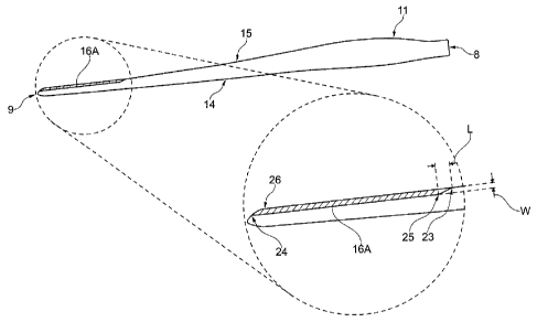
Fig. 3 shows an exemplary embodiment of the wind turbine blade 11 according to
the
invention. The wind turbine blade 11 may have an optimised aerodynamic blade
pro-
file along the length of the wind turbine blade, as shown in fig. 3. The
extended shell
section 16A may be located towards the tip end 9, as shown in the enlarged
image in
fig. 3. The extended shell section 16A may comprise a first point 23 facing
the blade
CA 02854384 2014-06-16
17
root 8 at which the extended shell section 16A is introduced onto the wind
turbine
blade 11. The extended shell section 16A may be extended along the length of
the
wind turbine blade 11 and may comprise a second point 24 facing the tip end 9
at
which the extended shell section 16A may be tapered off. The wind turbine
blade 11
may have a relative length of 1 and the extended shell section 16A may have a
relative
length of 0.40 or less.
The extended shell section 16A may at the point 23 be shaped so that the
profile of
that shell section 16A is gradually introduced towards a first intermediate
point 25
facing the tip end 9. The relative width of the extended shell section 16A may
between
these two points 23, 25 form a slope between 1:5 and 1:15 relative to the
trailing edge
15. The slope may be selected based on the width W of the extended shell
section 16A
and the length L between the point 23 and the intermediate point 25. The point
23 may
be located at a relative distance of 0.60 or more from the blade root 8.
The point 24 may be located at the tip end 9 of the wind turbine blade 11. The
extend-
ed shell section 16A may at the point 24 be shaped so that the profile of that
shell sec-
tion 16A is tapered off from a second intermediate point 26 and towards the
point 24.
The intermediate point 26 may face the blade root 8. The extended shell
section 16A
may maintain its maximum relative width between the two intermediate points
25, 26.
Fig. 4 shows an exemplary embodiment of a manufacturing process for the wind
tur-
bine blade 11. In a first step, a first set of layers (not shown) forming a
laminate 27
may be arranged in a first mould 28 and a second set of layers (not shown)
forming a
laminate 29 may be arranged in a second mould 30. The two laminates 27, 29
define
the first and second shell parts 16, 17, as shown in fig. 2. The layers may be
made of
fibre reinforced plastics or composites in which the fibres are organic fibres
or made
of glass or carbon.
One or both moulds 28, 30 may comprise at least one protrusion 31, 32
extending
outwards from an outer surface 33, 34 of the mould 28, 30. The protrusion 31,
32 may
form an elongated element extending along at least a part of the length of the
mould
28, 30. The layers may be positioned over the protrusion 31, 32 so that the
protrusions
31, 32 form a notch or raised area in the laminate 27, 29, as shown in fig. 4.
The pro-
CA 02854384 2014-06-16
18
trusion 31, 32 may have a height that is equal to or greater than the
thickness of the
laminate 27, 29. The protrusion 31 on the first mould 28 may be aligned with
the pro-
trusion 32 on the second mould 30. The raised areas may define two gluing
surfaces
35, 36 facing each other which are arranged at the leading edges 18, 22 of the
two
shell parts 16, 17.
Another protrusion 37, 38 may be arranged at the opposite end of one or both
moulds
28, 30 and extending outwards from the outer surface 33, 34 of the mould 28,
30. The
protrusion 36, 37 may form an elongated element extending along at least a
part of the
length of the mould 28, 30. The layers may be placed adjacent the protrusion
37, 38 or
alternatively over the protrusions 37, 38 so that they form a notch in the
laminate 27,
29. The protrusion 37 on the first mould 28 may be offset relative to the
protrusion 38
on the second mould 30 so that the first shell part 16 forms an extended shell
section,
as shown in fig. 2B. The protrusion 37, 38 may have a height that is equal to
or less
than the thickness of the laminate 27, 29. The protrusions 37, 38 may be
arranged at
the trailing edge 19, 21 of the shell part 16, 17. A gluing surface 39 may be
arranged
adjacent to the trailing edge 21 on the inner surface 23.
The laminates 27, 29 may in a second step be infused using a resin, e.g.
epoxy, sup-
plied by an external system (not shown), e.g. a vacuum infusion system. The
resin
may be distributed over the surface of the laminate 27, 29 through an
arrangement of
pipes or hoses coupled to the external system. The arrangement of pipes or
hoses may
be removed when the resin is cured.
At least one non-bonding layer 40 may be arranged on the inner surface 20a of
the
first shell part 16, i.e. on the extended shell section, in a third step. The
non-bonding
layer 40 may be placed adjacent to or near the trailing edge 19. The non-
bonding layer
40 may be arranged to mask off a gluing surface 41 on the surface 20a which
faces the
gluing surface 39. The non-bonding layer 40 may be a layer of a peel-ply
material,
e.g. a fibre reinforced fabric or nylon fabric coated with a release agent,
such as Tef-
lonTm. The peel-ply layer 40 may be shaped as an elongated flat element, e.g.
a tape,
which may be pre-manufactured or cut into the desired width and then applied
to the
surface 20a. Another non-bonding layer (not shown) may be arranged on an
external
surface 33a, 34a adjacent to one or more of the protrusions 31, 32, 37, 38.
CA 02854384 2014-06-16
19
A deformable element 42, e.g. a foam element, may be arranged on the opposite
side
of and adjacent to the gluing surface 41. The deformable element 42 may
comprise a
plurality of open or closed cells that allows the element 42 to deform when
subjected
to an extern pressure. The deformable element 42 may have a size and shape
that is
greater than the internal thickness and/or volume formed between the two shell
parts
16, 17 at that location. The element 42 may then deform, i.e. buckle or deform
in-
plane as shown in fig. 4, when the two shell parts 16, 17 are pressed
together.
At least one layer of an adhesive (not shown), e.g. a glue, may be applied to
one of the
gluing surfaces 35, 36 and one of the gluing surfaces 39, 41, preferably to
the gluing
surfaces 35, 41 of the first shell part 16. The adhesive may have a high
viscosity and a
high bonding capacity to the laminate 27, 29, such as epoxy.
The second shell part 17 may then be arranged over and aligned with the first
shell
part 16 in a fourth step. The two shell parts 16, 17 may then be brought into
contact
with each other so that the gluing surfaces 35, 36, 39, 41 are pressed
together. Any
excess adhesive may then be pressed out at least onto the non-bonding layer 40
and
onto the excess material at the leading edge 18, 22 or the non-bonding layer
thereof.
Any excess adhesive which is pressed out between the gluing surfaces 39, 41
and onto
the non-bonding layer 40 may be removed in a fifth step by peeling off the non-
bonding layer 40. This is preferably done after demoulding the two shell parts
16, 17
and before the adhesive has completely cured.
The glued region left behind by the non-bonding layer at the trailing edge 21
may be
manually grinding or polishing into a smooth transition with a minimal effort
in a
sixth step, if needed. Thereby reducing the workload needed to work the
surface into
its final shape since it does not have to be worked into a thin profile like a
convention-
al trailing edge.
Fig. 5 shows the extended shell section 16A with a first exemplary embodiment
of a
noise reduction profile 43. The noise reduction profile 43 may be arranged
along the
length of the extended shell section 16A, as shown in fig. 5.
CA 02854384 2014-06-16
The laminate 27 of the first shell part 16 may during lay-up be shaped into a
noise
reducing profile 43 at the trailing edge 19. The laminate 27 may be arranged
so that
the trailing edge 19 forms a sinus shaped edge 44. The peaks 44a, 44b of the
trailing
5 edge 44 may face in opposite directions and are preferably arranged out-
of-plane rela-
tive to the profile of the extended shell section 16A. The noise reducing
profile 43
may form a predetermined number of curves or waves extending parallel to the
chord
C. The amplitude of the peaks 44a, 44b may be tapered off from the trailing
edge 44
towards the trailing edge 21. This allows the noise reduction profile 43 to be
integrat-
10 ed into the shell parts 16, 17 so that they are manufactured in the same
step, thus re-
ducing the total manufacturing time.
Fig. 6 shows the extended shell section 16A with a second exemplary embodiment
of
the noise reduction profile 43. The noise reduction profile differs from the
profile 43
15 shown in fig. 5 by having a stepped profile 43' instead.
The laminate 27 may during lay-up be arranged so that the trailing edge 19
forms a
stepped edge 45. The peaks 45a, 45b of the trailing edge 45 may face in
opposite di-
rections and are preferably arranged out-of-plane relative to the profile of
the extended
20 shell section 16A. The noise reducing profile 43' may form a
predetermined number
of areas 46, 47 that are offset relative to each other, e.g. one area 46 that
are offset
towards the pressure side 12 and an adjacent area 47 that are offset towards
the suc-
tion side 13. The areas 46, 47 may have a predetermined length and width and
may be
placed in a predetermined positive or negative angle relative to the trailing
edge 21.
The transition surface between two adjacent areas 46, 47 may be configured to
form a
smooth transition.