Note: Descriptions are shown in the official language in which they were submitted.
1
OLEO-PNEUMATIC SHOCK ABSORBER
Background
An aircraft landing gear generally includes a shock absorber arranged to
perform spring and
damper functions. The shock absorber may contain hydraulic fluid, such as oil.
An example of
such a shock absorber is the "oleo-pneumatic" type, which combines oil and gas
within a vessel
to perform spring and damper functions.
For a fluid-containing shock absorber, the quantity of fluid present in the
vessel is important in
terms of ensuring the appropriate performance thereof However, leakage and
inappropriate
servicing can lead to an inappropriate quantity of fluid in the vessel.
The present inventor has identified that a need exists for a means by which
the appropriateness of
the fluid level within such a shock absorber or other vessel can be determined
in a manner which
is one or more of: quick; simple; reliable; cheap to employ; and a low burden
in terms of adding
additional weight and/or complexity to the shock absorber.
Summary
In accordance with a first aspect of the present invention, there is provided
a gauge for indicating
whether the oil level in an oleo-pneumatic shock absorber requires
modification, the gauge
comprising:
a substrate for positioning relative to the oleo-pneumatic shock absorber, the
substrate
comprising:
a first region arranged to encompass a range of possible oil levels within the
oleo-
pneumatic shock absorber;
a second region corresponding to a range of possible extension states of the
oleo-
pneumatic shock absorber; and
a third region comprising one or more traces, each trace corresponding to a
temperature
value and being indicative of an optimum relationship between the range of
can_dms. M1990960\1
CA 2854713 2018-05-14
CA 02854713 2014-05-06
WO 2013/068725
PCT/GB2012/052723
2
possible oil levels and the range of possible extension states at the
respective temperature
value associated with the trace.
Thus, the invention according to this aspect provides a gauge which can be
used in
maintenance situations to determine whether the fluid level, such as oil
level, within a
shock absorber requires modification. The fluid level in the shock absorber is
determined
to identify a point within the first region. This is generally achieved by
locating a
boundary between first and second fluids within the vessel i.e. a fluid
interface such as an
oil/gas interface. Knowing the temperature of the fluid and the extension
state of the shock
absorber, the user can visually compare the measured point within the first
region with the
optimum value given by the respective trace to determine whether the fluid
level requires
modification. Thus, a user may rapidly select the correct course of action
substantially
without the exercise of particular expertise, calculation or reference to
other data sources.
The third region may comprise a plurality of traces, each trace corresponding
to a different
temperature value.
The range of possible oil levels may be a range of possible oil levels during
in-use, on-
ground, conditions of an aircraft.
The substrate may comprise a hard material, such as hard plastics or a metal,
for example
aluminium.
The first region may be arranged to define an x-axis. The second region may be
arranged
to define a y-axis. The third region may be arranged to define a graph between
the x-axis
and y-axis.
The first region may comprise a space adjacent an edge of the substrate.
The first region may comprise a slot in the substrate. The slot may be sized
to
accommodate a measurement portion of an ultrasonic transducer.
CA 02854713 2014-05-06
WO 2013/068725 PCT/GB2012/052723
3
In accordance with a second aspect of the present invention, there is provided
an aircraft
landing gear comprising an oleo pneumatic shock absorber and a gauge according
to the
first aspect attached to the shock absorber such that the first region of the
gauge
encompasses a range of possible oil levels for the shock absorber.
The range of possible oil levels may comprise a range of possible oil levels
during in-use,
on-ground conditions.
In accordance with a third aspect of the present invention, there is provided
an aircraft
including an aircraft landing gear according to the second aspect.
In accordance with a fourth aspect of the present invention, there is provided
a method of
indicating whether a quantity of first fluid within a vessel containing the
first fluid and a
second fluid separated by a fluid interface requires modification, the method
comprising
the steps of:
identify a first point within a first region of a gauge, the first point
corresponding to
the interface between the first and second fluids;
identifying a second point within a second region of the gauge, the second
point
corresponding to an extension state of the vessel;
identifying a coordinate in a third region of the gauge, the coordinate being
defined
by the first and second points, the third region comprising one or more
traces, the each
trace corresponding to a temperature value and being indicative of an optimum
relationship
between the a range of possible values for the fluid interface and a range of
possible values
for the extension state at the respective temperature value associated with
the trace;
measuring the temperature of a fluid or solid which is relatable to the first
or second
fluid;
identifying a trace corresponding most closely to the measured temperature;
and
comparing the coordinate with the identified trace to indicate whether the
quantity
of first fluid requires modification.
The step of identifying a first point within a first region may comprise
moving an
ultrasonic sensor within the first region to identify the first point
corresponding to the fluid
CA 02854713 2014-05-06
WO 2013/068725
PCT/GB2012/052723
4
interface. The step of measuring the temperature of a fluid or solid which is
relatable to the
fluid may comprise using the ultrasonic sensor to measure the temperature of
the first fluid.
The vessel may be an oleo-pneumatic shock absorber. The first fluid may
comprise oil.
The second fluid may comprise a gas, such as nitrogen.
Brief Description of the Drawings
By way of example only, certain embodiments of the invention will now be
described by
reference to the accompanying drawings, in which:
Figure la is a diagram an aircraft landing gear including a conventional oleo-
pneumatic
shock absorber in an extended state;
Figure lb is a diagram of the aircraft landing gear of Figure la with the oleo-
pneumatic
shock absorber in a compressed state;
Figure 2 is a diagram of an aircraft landing gear according to an embodiment
of the present
invention, including the oleo-pneumatic shock absorber of Figure 1 a in
combination with a
gauge according to an embodiment of the present invention; and
Figure 3 is a diagram of the gauge of Figure 2.
Detailed Description
Referring to Figures la, a diagram of a conventional aircraft landing gear 100
is shown.
For clarity, not all parts of the landing gear 100 are shown.
The landing gear 100 includes a conventional oleo-pneumatic shock absorber
101. A
person skilled in the art will be familiar with such a shock absorber 101 and
as such, for
brevity, its function will only be described briefly. The shock absorber 101
has a casing
102 and a rod 104 slidably mounted therein. A wheel assembly 110 is coupled to
a lower
region of the rod 104. The shock absorber 101 defines a vessel (not shown)
which varies
in volume in accordance with the level of extension of the shock absorber 101.
The vessel
includes oil and nitrogen gas. The oil level within the shock absorber 101 is
defined by a
fluid interface 106, this being a generally planar interface between the oil
and gas within
CA 02854713 2014-05-06
WO 2013/068725 PCT/GB2012/052723
the vessel. This interface 106 can be detected in a number of ways, some of
which are
described in more detail below.
When the shock absorber 101 is in a relatively extended condition, as shown in
Figure 1a,
5 the oil level 106 is at a relatively low level. Referring additionally to
Figure lb, when the
shock absorber 101 is in a relatively compressed condition, as shown in Figure
lb, the oil
level 106 is at a relatively high level, due to compression of the gas within
the vessel.
Thus, a range of possible oil levels 108 is defined.
Figure 2 shows an aircraft landing gear 11 according to an embodiment of the
present
invention. For clarity, not all parts of the landing gear 11 are shown.
Like the known landing gear 100, the landing gear 11 of the illustrated
embodiment
includes a conventional oleo-pneumatic shock absorber 101. However, the shock
absorber
101 is in combination with a gauge 10 according to an embodiment of the
present
invention.
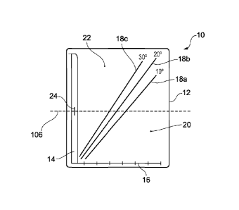
Referring additionally to Figure 3, the gauge 10 comprises a generally
rectangular plate 12
made from aluminium or any other suitable hard material, such as metal or hard
plastics.
The gauge 10 may be attached to the shock absorber 101 by any suitable means,
such as
bonding with adhesive or by way of a suitable mechanical fixing.
A slot 14 formed through a major face of the plate 12. The slot 14 extends
along and
parallel to an edge of the plate 12 and defines a first region arranged to
encompass the
range of possible oil levels 108 within the oleo-pneumatic shock absorber 101.
By
"encompass", it is meant that a range of possible oil levels cross or in some
other way are
relatable to the slot 14 such that the oil level may be detected by a sensor
located within the
slot 14. As such, the slot 14 defines a guide channel within which a sensor,
such as an
ultrasonic sensor, may be positioned and swept to find the oil level 106
within the shock
absorber 101. The slot 14 may be considered as defining a y-axis having a
range of
possible values to which the oil level 106 may correspond.
CA 02854713 2014-05-06
WO 2013/068725 PCT/GB2012/052723
6
The plate further includes an x-axis 16 which defines a second region
corresponding to a
range of possible extension states of the oleo-pneumatic shock absorber 101.
For example,
the number of inches or centimetres between two measurable points on the
landing gear,
such as the distance between the casing 102 and the wheel assembly 110. In
this
embodiment, the x-axis is substantially orthogonal with respect to the
longitudinal axis of
the slot 14. The x-axis 16 and its values may be marked in any visually
apparent manner;
non-limiting examples are by engraving, painting or the like.
The area between the slot 14 and x-axis 16 defines a third region comprising,
in the
illustrated embodiment, three traces 18a, 18b, 18c. Each trace 18a, 18b, 18c
corresponds to
a temperature value for the oil within the shock absorber 101. For example,
trace 18a is for
an oil temperature of 10 C, trace 18b is for an oil temperature of 20 C and
trace 18c is for
an oil temperature of 30 C. Any suitable number of traces may be provided,
keeping in
mind the balance between resolution and clarity. Each trace 18a, 18b, 18c
provides a
.. graphical representation of an optimum relationship between the range of
possible oil level
values within the slot 14 and the range of extension states on the x-axis 16
at the respective
temperature value associated with the trace 18a, 18b, 18c. The trace 18a, 18b,
18c may be
marked in any visually apparent manner; non-limiting examples are by
engraving, painting
or the like.
While in the illustrated embodiment the traces represent oil temperature
values, in other
embodiments the temperature values may be ambient temperature or the
temperature of the
shock strut. However, oil temperature may provide the highest degree of
accuracy and in
embodiments where the gauge is arranged for use with an ultrasonic sensor to
determine
the oil/gas boundary, the time of flight measurement may advantageously be
used to
determine the temperature of the oil, by knowing both the dilation of the
vessel and the
speed of sound in oil dependency with temperature.
In use, with the landing gear 11 supporting an aircraft on the ground (not
shown), the oil
.. level 106 of the oleo-pneumatic shock absorber 101 may be determined by
running a
sensor along the slot 14 to identify a point within the first region which
coincides with the
general plane of the oil level 106. Knowing the temperature of the oil and the
extension
state of the shock absorber 101, the user can visually compare the measured
point in the
CA 02854713 2014-05-06
WO 2013/068725 PCT/GB2012/052723
7
first region 14 to the optimum value given by the respective trace 18a, 18b,
18c to
determine whether the oil level requires modification. For example, a
coordinate defined
by the measured point within the first region 14 corresponding to the oil
level 106 and the
measured extension state may be determined within the third region and if the
coordinate is
on a first side 22 of the respective trace then the user knows that oil should
be removed,
and if the coordinate is a second side 20 of the respective trace then the
user knows that oil
should be added. Thus, a user may rapidly select the correct course of action
substantially
without the exercise of particular expertise, calculation or reference to
other data sources.
While the gauge has been described for use with a oleo-pneumatic shock
absorber, in other
embodiments the gauge may be arranged to indicate whether the fluid level in
any suitable
vessel having a fluid/fluid interface, such as a liquid/gas interface,
requires modification.
For example, the gauge may be used with reservoirs, hydraulic accumulators and
the like.
The gauge according to embodiments of the invention may have any suitable
first region
arranged to encompass a range of possible fluid levels within a fluid-
containing shock
absorber and enable or permit the fluid level to be determined. For example,
rather than
including a slot 14, the gauge may be arranged for a sensor to be swept along
its side face.
In other embodiments the gauge may include a fluid detection strip that
measures the
temperature within the shock absorber to find the fluid level. For example,
the gauge may
include a strip that changes colour dependent on temperature. In such a case,
the wall of
the shock absorber, or other vessel, should be arranged to permit a reading,
such as being
thin enough to permit a temperature difference between the oil filled area and
gas filled
area to be identified if both are heated, or cooled, and then allowed to
return to the ambient
state; in such a case, the surface adjacent to the gas would cool or heat more
rapidly than
the surface adjacent to the liquid, allowing an indication by temperature of
the gas/liquid
interface.
It should be noted that the above-mentioned embodiments illustrate rather than
limit the
invention, and that those skilled in the art will be capable of designing many
alternative
embodiments without departing from the scope of the invention as defined by
the appended
claims. In the claims, any reference signs placed in parenthesis shall not be
construed as
limiting the claims. The word "comprising" can mean "including" or "consisting
of' and
CA 02854713 2014-05-06
WO 2013/068725
PCT/GB2012/052723
8
therefore does not exclude the presence of elements or steps other than those
listed in any
claim or the specification as a whole. The singular reference of an element
does not
exclude the plural reference of such elements. In an apparatus claim
enumerating several
parts, several of these parts may be embodied by one and the same item of
hardware. The
mere fact that certain measures are recited in mutually different dependent
claims does not
indicate that a combination of these measures cannot be used to advantage.