Note: Descriptions are shown in the official language in which they were submitted.
CA 02854767 2016-08-02
Mainline Electric Oil Pump Assembly and Method for Assembling the Same
Technical Field
The mainline electric oil pump assembly relates to the field of assemblies for
pumping oil in
main oil pipelines.
Background
There has been known a shock-absorbing base frame of a pump assembly (RU
Patent
103584, IPC F04D29/00, pub1.20.04.2011, the patent owner - 000 "NKMZ"),
comprising self-
correcting adjustable mounting means (or in more correct terminology ¨
mounting supports).
However, as it describes a base frame of pump assembly rather than the
electrical pump assembly as
a whole, comprising a single-stage double-volute centrifugal pump, an electric
drive motor, the
shafts of which are coupled by a coupling, and a base (or mounting) frame
having supports mounted
under the feet of a pump and/or a motor, a number of features of the
interaction of all of the major
components of the assembly were not considered.
There has been known a centrifugal electric pump assembly, comprising a pump
and a motor
mounted on a common foundation base and coupled by a coupling (RU Patent
95043, IPC
FO4D1/00, F16D3/50, pub1.10.06.2010). It is argued that the technical effect
is to reduce wear of
bearings, motor overheating, noise and vibration.
However, this assembly relates to the nuclear industry, and therefore does not
take into
account the characteristics of mainline electric oil pump assemblies.
Furthermore, this patent
focuses on the specific problem of improving the design of a flexible coupling
between the pump
and motor shafts. A flexible coupling for centrifugal pump unit has been
specifically described in
RU Patent 2246047 (IPC F04D29/62, pub1.10.02.2005), however, the disadvantages
of this coupling
include relatively low operational reliability, ageing and thermal ageing of
rubber flexible elements
with change of the elasticity coefficient of rubber under large variations in
temperature, especially in
the presence of oil vapours and possible contact with oil when using the
coupling in mainline
centrifugal oil pump.
As for the pump being the most important and challenging component of the
mainline
electric oil pump assembly, there has been known a double-volute centrifugal
pump for pumping oil
of JSC Sumskoy plant "Nasosenergomash" (Patent of Ukraine 22403, IPC FO4D
1/00,
1
CA 02854767 2016-08-02
pub1.24.04.2007). The pump comprises a housing within which the rotor is
mounted, on whose
shaft bearings, pump rotor mechanical seals and an impeller, which together
with the inlet volume
and expanding volute of the housing constituting a flow area are fixed. The
housing is further
installed with a circulation system of lubrication and cooling of inner cavity
of mechanical seals,
and the impeller mounted to a shaft is split in two halves. The presence of
the two halves of the
impeller enables to double reduce the vibration characteristics of the pump by
mounting the halves
of the impeller to the shaft of the rotor with the rotation of one half
relative to the other about the
axis of the rotor on the half angle between the blades. Rotation of the halves
is provided by a
suitable arrangement of the key grooves. A disadvantage of this pump is
presence of keys and key
grooves, which weaken the shaft of the rotor and are being stress
concentrators, given the
fundamental presence of the backlashes in keyed connections, the presence of
key grooves on the
shaft facilitating excitation of vibrations of the pump rotor.
There has been also known almost the same double-volute centrifugal pump for
pumping oil
of the same patent holder - JSC Sumskoy plant "Nasosenergomash" (together with
JSC "VNIIAEN"
(Sumy, Ukraine)) (RU Patent 106680, IPC FO4D1/00, F04D29/00, pub1.20.07.2011).
The
disadvantage of this pump are gaps in the bearing sliding supports that causes
dynamic beats in the
gaps that contribute to increased vibration and noise of the pump.
Regarding the analogue method for assembling the frame-mounted pump assembly
by means
of its high-efficiency assembly, casting, machining and polishing (or
grinding) there has been
known a published international PCT application W02010030802 (IPC FO4D 17/02,
pub1.18.03.2010) for a method of assembly of a high-efficiency three-stage
horizontal centrifugal
pump as a part of an electric pump assembly. However, this method is still not
designed for the
assembly of the mainline electric oil pump assembly and therefore does not
take into account many
of design features of such assembly.
Also there has been known a method of manufacturing a horizontal pedestal-
mounted
(analogue of a base frame) pump assembly described in UK Patent 1255169 (IPC
F04C19/00,
pub1.01.12.1971) using machining of several pump surfaces for subsequent
critical connections
during a single set-up. However, the described pump is not a mainline oil pump
type and therefore
this method of manufacturing is not designed for the assembly of the mainline
electric oil pump
assembly and therefore does not take into account many of the design features
of such assembly.
As an analogue of method for high-efficiency frame-mounted assembling has been
known a
method for assembling a horizontally oriented turbo compressor unit (RU Patent
2263247, IPC
F16M5/00, F16M9/00, FO1D25/28, publ. 27.10.2005), consisting of a turbo
compressor group
2
= CA 02854767 2016-08-02
(functional analogue of a pump) and a charger (a functional analogue of a
motor), and their frames
(mounting and transport and technological ones) with support surfaces.
The disadvantages of this method include the use of complex and time-consuming
methods of
assembling and installation of the unit on the frames and the use of spacer
shims (or plates with
measured thickness) with a number of important limitations to use.
Summary of the Invention
The main overall aim of the present invention is to create a mainline electric
oil pump
assembly with improved technical and economic characteristics, in particular,
with reduced noise
and vibrations, increased reliability, service life and performance through a
set of design and
technological improvements in all core components of the assembly integrated
by a single inventive
concept.
Technical effect of improved construction of the assembly is achieved by that
in part of
improvements of basic components integrated by a single inventive concept, the
mainline electric
pump assembly comprises a mainline horizontal single-stage double-volute pump,
an electric drive
motor, a coupling, connecting pump shaft and motor shaft, and a common or
separated frames for
mounting the pump and motor thereon, the said pump comprising a housing with
two semi-volute
inlets and a double-volute outlet, a cover, a pump rotor consisting of the
pump shaft and an impeller
being installed between the housing and the cover, the impeller being seated
on the pump shaft by
way of a double-sided collet clamping device having taper sleeves and screws,
the pump rotor
mechanical seals being seated on the pump shaft by way of single-sided collet
clamping devices
having taper sleeves and screws, the single-sided collet clamping devices
being a combination of
two coaxial rings with tapered working surfaces with rings being slidable by
using clamping screws
along the axis of the pump shaft relative to each other to clamp the pump
shaft. The pump rotor is
mounted in internal relative to the housing console supports of roller
bearings of two types: double-
row spherical roller bearing taking up axial load of the pump shaft, and the
floating toroidal roller
bearing, both bearings being mounted on the pump shaft on tapered adapter
sleeves in axial section,
all connections of between the housing and the cover being fastened in pairs
including removable
tapered pins with threaded ends. For safe sealing of bearing assemblies screw
seals may be used.
Furthermore, to reduce bearing stress concentration, the generant of the inner
cylindrical surface of
the inner ring of the clamping device in areas near the ends is second-ordered
curved, on the end
3
= CA 02854767 2016-08-02
faces of all high strength steel alloyed taper sleeves: collet clamping
devices and clamping sleeves
these ends can be micron-accurate smoothed.
The pump housing has side twin semi-volute inlets of double-volute of the pump
consisting of
an inlet, a volute and a confuser area in front of the entrance of the flow in
the impeller, and
characterized by the reference and intermediate cross sections of the inlet
volute part, an angle of
contact of inlet volute part and the presence of the tongue of the volute
separating the liquid flows
going through the volute part and the inlet. The improved inlets have
reference and intermediate
cross sections of volute part reduced by 15 .. 20% of flow efficiency, angle
of contact of inlet volute
part increased up to 200 ... 2100 and the tongue of modified shape gradually
tapered from the
periphery to the center.
The pump and the electric motor are installed in substantially zero-backlash
fashion by pump
feet and motor feet via the mounting supports on the common or separated
frames, fixing of the
pump and the motor to a common or separated frames is made using the highly
precise height-
adjustable and angle self-correcting mounting supports, the mounting surfaces
of the pump feet are
raised to the level of a common central axis of the suction and discharge
nozzles of the pump, a
compensating dual disc coupling having flexible discs is being also used, the
mounting support
consisting of three gaskets, two lower gaskets are being connected by a thread
allowing changing
the height of mounting support, middle and upper gaskets having interfacing
spherical surfaces with
the same radius of curvature, all of the said gaskets having a common axial
hole for the mounting
bolt and nut for the final clamping of the pump feet and the motor feet to the
frame by bolt and nut
through the common through hole, two lower gaskets having blind radial holes
to enable using
leverage when adjusting the height of the mounting support.
The coupling connecting the pump shaft and the motor shaft is a compensating
dual disc
coupling and consists of a combination of two identical couplings connected by
an intermediate
shaft, each coupling having flexible hardened steel disc (or a set (pack) of
discs) mounted between
its two half couplings, to discharge discs in the couplings there installed
roller joints in the form of
spherical double-row roller bearings, each of the two couplings having the
same even number of
clamping fixtures of set of discs, opposite directed sleeves of the fixtures
are disposed on the flanges
of half couplings next but one, uniformly and on a same radial distance from
the common central
axis of rotation of couplings, the pump shaft and the motor shaft, wherein the
oppositely directed
clamping fixtures of flexible discs of both couplings are coaxial.
A technical effect of the method for assembling the pump assembly is achieved
by high-
precision and virtually zero-backlash technology process of assembling using
the base components
consisting of a sequence of the following techniques: first, assembling the
pump, and then
4
CA 02854767 2016-08-02
assembling the entire pump assembly. Before assembling the pump, in the cast
housing and cast
cover seating surfaces of pump feet of the housing and the parting planes - a
common horizontal
plane of the housing and the cover and vertical mating planes around the pump
shaft holes, are
basically polished to install housings of bearing assemblies housings. To bore
holes for adjusting
rings of the pump rotor axial clearance in the housing, gap seal holes of the
impeller and bearing
holes in the bearing assembly housings between the housing and the cover and
through the empty
bearing assembly housings on a boring machine in a single set-up operation, a
boring bar with
regulated overhang boring tools is preset, then the housing and the cover are
coupled by pins and
two removable taper pins with threaded ends on the horizontal plane of their
parting, and empty
bearing assembly housings are coupled by screws and pairs of removable tapered
pins with threaded
ends on the vertical parting planes with the pump housing and the cover. After
boring of the holes in
a single set-up the housing and the cover are disconnected removing all
removable taper pins.
Regardless of the boring operation in a single set-up the pump rotor is
assembled of the pump shaft,
the impeller and the two shaped sleeves on the pump shaft involved in the
formation of a pump flow
area, using double-sided collet clamping devices with taper sleeves and screws
and using tool in a
form of a tube of accurate dimensional length for accurate positioning of the
impeller on the pump
shaft, then shaped sleeves on both sides of the double-sided collet clamping
device are installed and
fixed. Then the pump rotor is mounted with axial clearance spacer rings being
preliminary mounted
on the pump shaft in the housing without cover, and the gaps between the
impeller and the rings
with the pump shaft axial locking relative to the housing are aligned, e.g. by
temporary spacers.
Regardless of the pump rotor mounting in the housing two bearing assemblies
with a double-row
spherical roller bearing taking up axial load, and a toroidal roller bearing,
being a floating one, and
therefore not taking up axial load, are separately assembled. Then adjustment
assembling is done,
followed by disassembling of the bearing assembly with a double-row spherical
roller bearing on the
pump shaft and the housing to provide substantial zero-backlash between the
mating planes of the
bearing assembly base and the housing at the expense of a corresponding
decrease in the thickness
of the compensatory ring. Prior to the final mounting of the cover to the
housing with pins and
tapered pins temporary spacers are removed from the pump shaft axial gaps
relative to the housing.
After mounting of the cover to the housing mechanical seals between the pump
shaft and assembled
housing are assembled, mechanical seals are fixed on the housing, for example,
with pins, and on
the pump shaft with a zero backlash single-ended collet clamping device with
taper sleeve and
screws. At the end of the pump assembling, bearing assemblies are finally set
on assembled housing
by using taper clamping sleeves between the bearings and the shaft, and the
radial clearance
5
CA 02854767 2016-08-02
between the impeller and the housing, including gap seals, is set by reusing
removable taper pins
between the bearing assemblies bases and the housing.
The connection of the pump cover and the pump housing is preferably securely
and zero-
backlash compacted or hermetically sealed with liquid gasket (anaerobic
sealant), with the
expectation of the end of cured sealant. The sealant cures in the absence of
air between zero-
backlash metal surfaces by compressed forces of tightening pins. Source liquid
monomer is
transformed into the polymer sealant caused by the compression force but
without the air for 1 ... 2
days and then securely holds the joint seal in the operating conditions of
high differential pressures.
Then follows the assembling of the electric pump assembly, comprising mounting
of the
pump and electric motor to a common or separate frames on a foundation,
connection (usually
welding) of pipes to flanges of the suction and discharge nozzles of the pump,
adjustment of the
alignment of the pump shaft and motor shaft, and the final coupling of the
pump shaft and motor
shaft via the coupling.
Mounting of the pump and the electric motor to a common or separate frames
with fasteners
to the frame is carried out using adjustable highly-precise mounting supports
and typically includes
the following sequence of techniques: mounting of a common frame or individual
frames to a
foundation, horizontal levelling of support surfaces at two levels, and
finally mounting the frames to
the foundation; fitting mounting of the pump and / or electric motor to the
common frame or
individual frames on the mounting supports; producing general through holes in
the mounting
supports, the pump feet and the motor feet and the corresponding seating
surfaces of the frame and
presetting of mounting bolts in produced through holes, welded or flanged
connection of the suction
and discharge nozzles of the pump with pipelines; adjustment and final
installation of all of the
mounting supports under the pump and the electric motor, simultaneously using
laser for precise
alignment of the pump shaft and motor shaft; final tightening of the mounting
bolts of the mounting
supports; connection of the pump shaft and the motor shaft exhibited coaxially
aligned and spaced
apart from each other by installing a compensating dual disc coupling with the
intermediate shaft.
Description of the Drawings
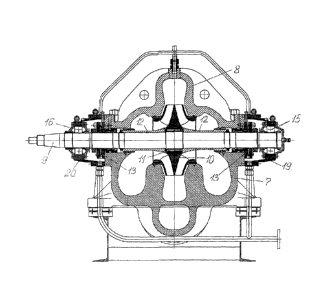
Fig. 1 is a general view of electric pump assembly;
Fig.2 is a view of a pump with connected pipelines;
Fig.3 is a perspective view of upgraded mainline oil pump;
Fig.4 is a general side cross-sectional view of a pump;
Fig. 5 is a gap-free double-sided clamping device for mounting impeller to a
shaft;
6
CA 02854767 2016-08-02
Fig. 6 is a gap-free single-sided clamping device of one of the two mechanical
seals of the shaft;
Fig. 7 is a bearing support (assembly) of the pump rotor with a toroidal
roller bearing;
Fig. 8 is a bearing support (assembly) of the pump rotor with a double-row
spherical roller bearing;
Fig. 9 is a mounting support under the pump foot and electric drive motor in a
scaled-up side
sectional view;
Fig. 10 is a general longitudinal cross-section of compensating dual disc
coupling between the pump
shafts and the electric drive motor;
Fig. 11 is a scheme of modified semi-volute pump inlet.
Description of Embodiment
In the figures in total numbering of the positions are marked the following
significant
components and parts in large scale. The most significant components and parts
of electric pump
assembly are: a horizontal single-stage double-volute pump 1, an electric
drive motor 2, a frame 3,
mounting supports 4 under the feet 5 of a pump and a motor, and a coupling 6.
The most significant
components and parts of a pump: a cast housing 7 with two semi-volute inlets
and a double-volute
outlet and a cast cover 8 of the pump housing (with a common horizontal plane
of the parting on the
common central plane of symmetry of the holes for the pump rotor), a pump
rotor consisting of
balanced and machined shaft 9 and impeller 10, a double-sided collet clamping
device 11 of the
impeller on the shaft, two shaped sleeves 12 on the shaft to form the flow
part of the pump, pump
rotor mechanical seals 13, single-sided collet clamping devices 14 on the
shaft, two different roller
bearings: double-row spherical roller bearing 15 and toroidal roller bearing
16, taper fastening
sleeves 17, 18 for bearings 19, 20, tube-type bearing housings (console
supports), bearing
lubrication and sealing system, sets of fasteners (screws, bolts, nuts, pins,
removable taper pins with
threaded ends).
To ensure a firm zero-backlash connection of the impeller and a shaft, a
clamping element
consisting of three major parts: a central ring into which identical side
rings are drawn by the force
of screw tightening, wherein the taper surfaces of the rings are pressed
against the tapered surfaces
of the ring, is used. The central ring and the side rings come into contact by
taper surfaces. The
connection is self-centering relative to the axis of rotation and is being an
easily mounted pressure
connection. The connection transmits considerable torque and axial forces.
To secure the connection of the housings, a taper ratio of removable taper
pins is small,
usually 1:50. To remove the pin its threaded end is used.
7
CA 02854767 2016-08-02
Taper clamping sleeves of bearings are equipped with axial section to increase
the flexibility
of the sleeve body.
The frame of the assembly is preferably manufactured of channels, under the
engineering
empirical recommendations the channel size is approximately 0.1 of the maximum
overall size of
the frame.
Factors affecting the characteristics of a conventional assembly, primarily
parameters of its
vibration and noise are the following:
- mechanical: rotor imbalance; shaft length of the rotor, its profile with key
grooves and
keyed connection with gaps; bearing supports; pump shaft and drive motor
misalignment; the degree
of non-rigid fixing of the assembly to the frame;
- hydrodynamic: blade vibration and off-design (unrated) operation of the
pump.
The main technical design solutions that improve the performance of the
referred
characteristics of the pump assembly reducing in the first place vibration and
noise of the pump
assembly are:
- the use of non-splined zero-backlash seating of the impeller on a smooth
shaft,
- the use of tailored roller bearings seated in a non-splined and zero-
backlash fashion on a
smooth shaft,
- the use of mechanical seals seated in a non-splined and zero-backlash
fashion on a smooth
shaft;
- the use of self-correcting height-adjustable spherical mounting supports
under the feet of
the pump and motor;
and the main technological solution: in the process of assembling the pump:
boring of the
seating surfaces of the pump housing for the rotor in a single set-up
operation.
The main advantage of using collet clamping devices with taper sleeves and
screws is a
complete replacement of splined connections, and thus removing the source of
dangerous stress
concentrators of rotor shaft that is guaranteed to have impact on reducing the
vibration activity and
increasing the resource of the pump rotor and the pump assembly as a whole.
Collet clamping
device has no backlash, does not damage the surface of the shaft and the hub,
easily installed and
removed of the clamping connection.
The main advantage of the use of tailored roller bearings, allowing floating
the rotor shaft
without bending (toroidal roller bearing) and easily perceiving changes of the
length of the shaft
caused by thermal displacements (double-row spherical roller bearing) is the
possibility of
significant shortening (15-20%) of the length of the shaft with bearings with
increasing rigidity and
8
= CA 02854767 2016-08-02
a corresponding decrease in its vibration activity. In addition, the tubular
bearing housings instead of
demountable semi-tubular bearing housings also improve the stiffness
characteristics of the pump.
Detailed assembling of the pump
Before assembling the pump, perform boring of holes with a boring bar on a
boring
machine in the housings in a single set-up operation (when boring of the said
holes the empty
bearing housings must be secured on the pump housing by screws and fixed by
the pairs of
removable taper pins).
Next, connect the rotor shaft and impeller by double-sided collet clamping
connection with
taper sleeves and screws. Secure position of the impeller relative to the
shaft through a tool in the
form of a tube with precise measuring length with disc and screw holes at the
end. When installing
the impeller, put the tube on the shaft all the way until the disc stops at
the end of the shaft and
through the hole in the disc attach it to the end of the shaft by screw.
Tighten the screws of the collet
connection in three bypass tightening torque 0.3T, 0.7T and T.
Set dummy screws to connect the impeller with a shaped sleeve on the side
opposite main
screws of collet connection.
Set the shaped sleeves on both sides of the impeller, secure them with nuts
and lock nuts.
Lower the shaft with pre-installed rings (centering rings) into the pump
housing and install
the rings in the grooves of the housing.
By displacing the shaft along the axis achieve gap equality between the
impeller and the
rings, insert temporary spacers (gauges) into these gaps for axial fixation of
the shaft relative to the
pump housing.
Separately, on mounting table assemble two bearing assemblies. When assembling
the
bearing assembly with a double-row spherical roller bearing insert the bearing
into the bearing
housing and fix it by dummy cap. Similarly, assemble another bearing assembly
with a toroidal
roller bearing.
On both sides of rotor shaft install machine seals, brass seal sleeves (they
may be sealed
with a screw) and compensating rings (not shown in the figures).
Install the bearing assembly on the shaft, insert a taper sleeve into the
bearing (from the
bearing kit) and secure with a nut. Install the screws to connect the bearing
housing to the pump
housing. Screwing up the said screws by hand and using the mounting gaskets
ensure that mating
planes of bearing housing and the pump are parallel. Measure with a gauge the
clearance between
the mating plane of the bearing housings and the pump housing. Having
dismantled the bearing
9
= CA 02854767 2016-08-02
assembly, remove the ring and reduce its thickness by the amount of clearance
that will allow in
final assembling to provide a corrected clearance between the mating planes of
the bearing housings
and the pump housing close to zero.
Remove temporary spacers from the axial (side) gaps.
Install the pump cover to the pump housing. To do this, having lubricated the
contacting
surfaces with a liquid gasket (anaerobic sealant-monomer), gently lower the
cover of the pump onto
the pump housing, install the pins and secure it to the housing, turning the
nuts in a few rounds.
Make sure that when the lid is lowered projections of the rings were in
response grooves of the
pump cover. Leave the construction alone for a time sufficient to polymerize
the sealant.
Assemble mechanical seals, having installed them so that one of the openings
for washing
of the mechanical seal was drawn towards the upper opening in the pump cover.
Secure the
mechanical seal on the pump housing by pins and on the shaft in the axial
direction by a single-sided
collet clamping device. Disassemble spring clips of mechanical seals.
Install the bearing assembly on the shaft, having pre-set a ring, a sleeve and
a compensating
ring (not shown). Install between the bearing and the shaft a taper clamping
sleeve, tighten the nut
by standardized torque and lock it. Tighten the screws by hand and, using the
mounting screw, align
the pin holes in the bearing housing with the mating holes in the pump
housing. Install tapered pins,
tighten and lock the screws.
Remove the dummy cover and install the cover in its place. By adjusting gasket
thickness
ensure the absence of the axial bearing clearance relative to its body.
When installing the support with toroidal roller bearing fit of the flanges of
the bearing
housing and the pump will be provided by the axial mobility of the roller
bearing rings. However, to
optimize the conditions of its operation, it is necessary to mate the end face
planes of inner and outer
rings, which is ensured by adjusting thickness of a compensating ring (not
shown). To do this,
install and secure the bearing assembly on the pump housing by tightening the
screws by hand, set a
tapered clamping sleeve into the bearing and tighten the nut. Measure the
relative displacement of
the outer and inner bearing rings and adjust the thickness of compensating
ring against the
displacement. Then finally install and secure the bearing assembly.
Check freedom of rotation of the assembled pump.
The assembling of the pump is over. If necessary, bearings and pump rotor
mechanical
seals being seated on the shaft may be replaced without disconnecting the
cover and the pump
housing.
Further is a description of the assembling process of the pump assembly in the
following
sequence of techniques: mounting of a common frame or individual frames to a
foundation,
CA 02854767 2016-08-02
horizontal levelling of their support surfaces at two levels, and finally
mounting the frames to the
foundation, fitting mounting of the pump and / or electric motor to the frame
or individual frames on
mounting supports; producing general through holes in the mounting supports,
pump feet and motor
feet and the corresponding mounting surfaces of the frame and presetting of
mounting bolts in
produced through holes, welded or flanged connection of suction and discharge
nozzles of the pump
with pipelines; adjustment and final installation of all of the mounting
supports under the pump and
the electric motor, simultaneously using laser for precise alignment of the
pump shaft and motor
shaft; final tightening of the mounting bolts of the mounting supports;
connection of the pump shaft
and the motor shaft exhibited coaxially aligned and spaced apart from each
other by installing a
compensating dual disc coupling with the intermediate shaft.
The assembling of the pump assembly is over. If necessary, the sleeve between
the shafts
can be removed without moving the pump or electric motor.
An example of assessing the benefits of a method for assembling the pump
assembly.
Preliminary tests of the pump assembly prototypes and expert evaluation showed
the
following relative values of impact of the proposed technical solutions,
primarily to reduce the
vibration of the pump assembly, shown in the table on a separate sheet.
Thus, as a result of all proposed inventive improvements of the pump assembly
(its
vibration activity and noise are reduced, and resource is increased), its
performance will be
substantially improved, and hence the main aim of the present invention
achieved.
11