Note: Descriptions are shown in the official language in which they were submitted.
CA 02855463 2014-07-02
MLP 7652.CA
1
PULLOUT RESISTANT SWING INSTALLATION TIE AND ANCHORING SYSTEM
UTILIZING THE SAME
BACKGROUND OF THE INVENTION
Field of the Invention
[0011 This invention relates to an improved anchoring arrangement for use in
conjunction with
cavity walls having an inner wythe and an outer wythe. More particularly, the
invention relates
to construction accessory devices, namely, veneer ties with modified pullout
resistant ribbon
pintles. The veneer ties are for emplacement in the outer wythe and are
further accommodated
by receptors in the cavity, which receptors extend from the inner wythe to
encapture the
specially configured pintles hereof. The invention is applicable to structures
having an outer
wythe of brick or stone facing in combination with an inner wythe of either
masonry block or
dry wall construction.
Description of the Prior Art
[002] In the past, investigations relating to the effects of various forces,
particularly lateral
forces, upon brick veneer masonry construction demonstrated the advantages of
having high-
strength wire anchoring components embedded in the bed joints of anchored
veneer walls, such
as facing brick or stone veneer. Anchors and ties are generally placed in one
of the following
five categories: corrugated; sheet metal; wire; two-piece adjustable; or joint
reinforcing. The
present invention has a focus on wire formatives and in particular, pintle
ties.
[003] Prior tests have shown that failure of anchoring systems frequently
occurs at the juncture
between the pintle of the veneer tie and the receptor portion of the wall
anchor. This invention
addresses the need for a high-strength pintle suitable for use with both a
masonry block or dry
wall construction that provides a strong pintle-to-receptor connection and
further provides high
strength pullout resistance combined with ease of installation within the wall
anchor.
[004] Early in the development of high-strength anchoring systems a prior
patent, namely U.S.
Patent No. 4,875,319 (319), to Ronald P. Hohmann, in which a molded plastic
clip is described
CA 02855463 2014-07-02
MLP 7652.CA
2
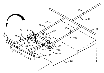
as tying together reinforcing wire and a veneer tie. The assignee of '319,
Hohmann & Barnard,
Inc., now a MiTek-Berkshire Hathaway company, successfully commercialized the
device under
the ScismiClip trademark. For many ycars, the white plastic clip tying
together the veneer
anchor and the reinforcement wire in the outer wythe has been a familiar item
in commercial
seismic-zone buildings.
[005] Additionally, the high-strength pintle hereof has been combined with the
swaged leg as
shown in the inventor's patent, U.S. Patent No 7,325,366. The combination item
reduces the
number of "bits and pieces" brought to the job site and simplifies
installation.
[006] The high-strength pintle is specially configured to prevent veneer tie
pullout. The
configured pintle restricts movement in all directions, ensuring a high-
strength connection and
transfer of forces between the veneer and the backup wall. The high-strength
pintle is
compressively reduced in height by the cold-working thereof to increase the
veneer tie strength.
Because the wire formative hereof employs extra strong material and benefits
from the cold-
working of the metal alloys, the anchoring system meets the unusual
requirements demanded in
current building structures. Reinforcement wires are included to form seismic
constructs.
[007] There have been significant shifts in public sector building
specifications which have
resulted in architects and architectural engineers requiring larger and larger
cavities in the
exterior cavity walls of public buildings. These requirements are imposed
without corresponding
decreases in wind shear and seismic resistance levels or increases in mortar
bed joint height.
Thus, the wall anchors needed are restricted to occupying the same 3/8-inch
bed joint height in
the inner and outer wythes. Thus, the veneer facing material is tied down over
a span of two or
more times that which had previously been experienced. Exemplary of the public
sector building
specification is that of the Energy Code Requirement, Boston, Mass. (See
Chapter 13 of 780
CMR, Seventh Edition). This Code sets forth insulation R-values well in excess
of prior editions
and evokes an engineering response opting for thicker insulation and
correspondingly larger
cavities.
CA 02855463 2014-07-02
MLP 7652.CA
3
10081 Besides earthquake protection requiring high-strength anchoring systems,
the failure of
several high-rise buildings to withstand wind and other lateral forces has
resulted in the
promulgation of more stringent Uniform Building Code provisions. This high-
strength pullout
resistant pintle is a partial response thereto. The inventor's related
anchoring system products
have become widely accepted in the industry.
[009] The following patents are believed to be relevant and are disclosed as
being known to the
inventor hereof:
U.S. Patent No. Inventor Issue Date
3,377,764 Storch April 16, 1968
4,021,990 Schwalberg May 10, 1977
4,373,314 Allan February 15, 1983
4,473,984 Lopez October 2, 1984
4,598,518 Hohmann July 8, 1986
4,869,038 Catani September 26, 1989
4,875,319 Hohmann October 24, 1989
5,454,200 Hohmann October 3, 1995
6,668,505 Hohmann et al. December 30, 2003
6,789,365 Hohmann et al. September 14, 2004
6,851,239 Hohmann et al. February 8, 2005
7,017,318 Hohmann March 28, 2006
7,325,366 Hohmann February 5, 2008
It is noted that these devices are generally descriptive of wire-to-wire
anchors and wall ties and
have various cooperative functional relationships with straight wire runs
embedded in the
interior and/or exterior wythe.
[010] U.S. Patent No. 3,377,764 - D. Storch - Issued April 16, 1968
Discloses a bent wire, tie-type anchor for embedment in a facing exterior
wythe engaging with a
loop attached to a straight wire run in a backup interior wythe.
[011] U.S. Patent No. 4,021,990 - B.J. Schwalberg - Issued May 10, 1977
Discloses a dry wall construction system for anchoring a facing veneer to
wallboard/metal stud
construction with a pronged sheetmetal anchor. Like Storch '764, the wall tie
is embedded in the
exterior wythe and is not attached to a straight wire run.
CA 02855463 2014-07-02
MLP 7652.CA
4
[012] U.S. Patent No. 4,373,314 - J.A. Allan - Issued February 15, 1983
Discloses a vertical angle iron with one leg adapted for attachment to a stud;
and the other
having elongated slots to accommodate wall ties. Insulation is applied between
projecting
vertical legs of adjacent angle irons with slots being spaced away from the
stud to avoid the
insulation.
[013] U.S. Patent No. 4,473,984 - Lopez - Issued October 2, 1984
Discloses a curtain-wall masonry anchor system wherein a wall tie is attached
to the inner wythe
by a self-tapping screw to a metal stud and to the outer wythe by embedment in
a corresponding
bed joint. The stud is applied through a hole cut into the insulation.
10141 U.S. Patent No. 4,598,518 - R. Hohmann - Issued July 7, 1986
Discloses a dry wall construction system with wallboard attached to the face
of studs which, in
turn, are attached to an inner masonry wythe. Insulation is disposed between
the webs of
adjacent studs.
[015] U.S. Patent No. 4,869,038 - M.J. Catani - Issued September 26, 1989
Discloses a veneer wall anchor system having in the interior wythe a truss-
type anchor, similar
to Hala et al. '226 supra, but with horizontal sheetmetal extensions. The
extensions are
interlocked with bent wire pintle-typc wall ties that are embedded within the
exterior wythe.
[016] U.S. Patent No. 4,879,319 - R. Hohmann - Issued October 24, 1989
Discloses a seismic construction system for anchoring a facing veneer to
wallboard/metal stud
construction with a pronged shectmetal anchor. Wall tie is distinguished over
that of Schwalberg
'990 and is clipped onto a straight wire run.
10171 U.S. Patent No. 5,454,200 - R. Hohmann - Issued October 1995
Discloses a facing anchor with straight wire run and mounted along the
exterior wythe to receive
the open end of wire wall tie with each leg thereof being placed adjacent one
side of
reinforcement wire. As the eye wires hereof have scaled eyelets or loops and
the open ends of
the wall ties are sealed in the joints of the exterior wythes, a positive
interengagement results.
CA 02855463 2014-07-02
MLP 7652.CA
[018] U.S. Patent No. 6,668,505 - Hohmann et al. - Issued December 30, 2003
Discloses high-span and high-strength anchors and reinforcement devices for
cavity walls
combined with interlocking veneer ties are described which utilize reinforcing
wire and wire
formatives to form facing anchors, truss or ladder reinforcements, and wall
anchors providing
wire-to-wire connections therebetween.
[019] U.S. Patent No. 6,789,365 - R Hohmann et al. - Issued September 14, 2004
Discloses side-welded anchor and reinforcement devices for a cavity wall. The
devices are
combined with interlocking veneer anchors, and with reinforcements to form
unique anchoring
systems. The components of each system are structured from reinforcing wire
and wire
formatives.
[020] U.S. Patent No. 6,851,239 - Hohmann et al. - Issued February 8, 2005
Discloses a high-span anchoring system described for a cavity wall
incorporating a wall
reinforcement combined with a wall tie, which together serve a wall construct
having a larger-
than-normal cavity. Further the various embodiments combine wire formatives
which are
compressively reduced in height by the cold-working thereof. Among the
embodiments is a
veneer anchoring system with a low-profile wall tie for use in a heavily
insulated wall.
[021] U.S. Patent No. 7,017,318 - Hohmann - Issued March 28, 2006
Discloses an anchoring system with low-profile wall ties in which insertion
portions of the wall
anchor and the veneer anchor are compressively reduced in height.
[022] U.S. Patent No. 7,325,366 - Hohmann - Issued February 5, 2008
Discloses snap-in veneer ties for a seismic construction system in cooperation
with low-profile,
high-span wall anchors.
[023] None of the above anchors or anchoring systems provide a veneer tie
having a high-
strength pullout resistant pintle veneer tie for fulfilling the need for
enhanced compressive and
tensile properties and ease of installation. This invention relates to an
improved anchoring
CA 02855463 2014-07-02
MLP 7652.CA
6
arrangement for use in conjunction with cavity walls having an inner wythe and
an outer wythe
and meets the heretofore unmet need described above.
SUMMARY
[024] In general terms, the invention disclosed hereby is a high-strength
pullout resistant pintle
veneer tie and an anchoring system utilizing the same for cavity walls. The
system includes a
wire-formative veneer tie for emplacement in the outer wythe. The high-
strength construction
system hereof is applicable to construction of a wall having an inner wythe,
which can either be
of dry wall construction or masonry block, and a masonry outer wythe, as well
as to insulated
and non-insulated structures. The wythes are in a spaced apart relationship
and form a cavity
therebetween. In the disclosed system, a unique combination of a wall anchor
(attachable to
either ladder- or truss-type reinforcement for masonry inner wythes or to
metal studs of a dry
wall construct), a wire veneer tie, and, optionally, a continuous wire
reinforcement is provided.
The invention contemplates that the veneer ties are wire formatives with high-
strength ribbon
pintles with an angled portion for ease of installation and a securement
portion to prevent veneer
tie pullout. The interconnecting portion of the wire formative veneer ties is
compressively
reduced in height by the cold-working thereof to increase the veneer tie
strength.
[025] In the first embodiment of this invention, the veneer tie is constructed
from a wire
formative and has configured ribbon pintles that provide a high strength
connection, restricting
vertical, lateral and horizontal movement and pullout when interconnected with
a wall anchor
and embedded in the bed joint of the outer wythe. The veneer tie is engaged
with a wall anchor
that is interconnected with a ladder- or truss-type reinforcement in a manner
similar to the wall
anchor shown in Hohmann, U.S. Patent No. 6,789,365. The anchor has two
configurations with
either a single eye or two eyes extending from the receptor portions into the
cavity between the
wythes. Each eye accommodates the interengagement therewith of the
interconnecting portion
of the veneer tie. The veneer tie is positioned so that the insertion end
thereof is embedded in the
bed joint of the outer wythe. The construction of the veneer tie results in an
orientation upon
CA 2855463 2017-04-18
81780898
7
emplacement so that the widest part of the first and second interengaging
portions are
subjected to compressive and tensile forces.
[026] The second embodiment further includes a dry wall construct inner wythe.
Here, the
drywall anchor is a metal stamping and can be attached by sheetmetal screws to
the metal
vertical channel members of the wall. Each dry-wall anchor accommodates in a
horizontally
extending portion, the interconnecting portion of the wire formative veneer
tie. The
securement portion of the interconnecting portion prevents veneer tie pullout,
while the angled
portion provides for ease of installation. In this embodiment the insertion
end of the veneer tie
is positioned on the outer wythe and optionally, a continuous reinforcement
wire can be
snapped into a variation of the veneer tie and secured to the outer wythe. The
snap-in feature
replaces the traditional function of the seismic clip for accommodating a
straight wire run (see
U.S. Patent No. 4,875,319) and receiving the open end of the box tie. This
anchor system with
a straight wire run are embedded in the bed joint of the outer wythe.
[026a1 Some embodiments disclosed herein relate to a wire-formative pintle
veneer tie for use
with an anchoring system in a wall having an inner wythe and an outer wythe in
a spaced
apart relationship the one with the other and having a cavity therebetween,
the outer wythe
formed from a plurality of courses with a bed joint of predetermined height
between each two
adjacent courses, the bed joint being filled with mortar, the veneer tie
comprising: an insertion
portion for disposition in the bed joint of the outer wythe, the insertion
portion comprising
two contiguous hook portions; two cavity portions contiguous with the
insertion portion; and,
a compressively reduced interconnecting portion comprising a first ribbon
pintle and a second
ribbon pintle, each ribbon pintle contiguous with one of the cavity portions
and set opposite
the insertion portion, the first ribbon pintle comprising: a first
interengaging portion extending
at a 90 degree angle from the respective cavity portion; and a securement
portion contiguous
with the first interengaging portion opposite the cavity portion, the
securement portion being
disposed at a first angle from the first interengaging portion; the second
ribbon pintle
comprising: a second interengaging portion extending at a 90 degree angle from
the respective
cavity portion; and an angled portion contiguous with the second interengaging
portion
=
CA 2855463 2017-04-18
81780898
7a
opposite the cavity portion, the angled portion being disposed at a second
angle from the
second interengaging portion, the second angle being different from the first
angle.
[026b] Some embodiments disclosed herein relate to a pintle anchoring system
for use in a
wall having an inner wythe and an outer wythe in a spaced apart relationship
the one with the
other and having a cavity therebetween, the outer wythe formed from a
plurality of courses
with a bed joint of predetermined height between each two adjacent courses,
the bed joint
being filled with mortar, the anchoring system comprising: a wall anchor
adapted to be fixedly
attached to the inner wythe and having a free end thereof extending into the
cavity, the free
end of the wall anchor comprising: one or more receptor portions disposed in
the cavity, the
one or more receptor portions being openings disposed horizontal; and, a wire-
formative
veneer tie comprising: an insertion portion for disposition in the bed joint
of the outer wythe,
the insertion portion comprising two contiguous hook portions; two cavity
portions
contiguous with the insertion portion; and, a compressively reduced
interconnecting portion
comprising a first ribbon pintle and a second ribbon pintle, each ribbon
pintle contiguous with
one of the cavity portions and set opposite the insertion portion,the first
ribbon pintle
comprising: a first interengaging portion extending at a 90 degree angle from
the respective
cavity portion; and a securement portion contiguous with the first
interengaging portion
opposite the cavity portion, the securement portion being disposed at a first
angle from the
first interengaging portion; the second ribbon pintle comprising: a second
interengaging
portion extending at a 90 degree angle from the respective cavity portion; and
an angled
portion contiguous with the second interengaging portion opposite the cavity
portion, the
angled portion being disposed at a second angle from the second interengaging
portion, the
second angle being different from the first angle.
[027] It is an object of the present invention to provide in an anchoring
system having an outer
wythe and an inner wythe, a high-strength veneer tie that interengages a wall
anchor which
system further includes a specially-configured veneer tie with pullout
resistant ribbon pintles. =
CA 2855463 2017-04-18
81780898
7b
[028] It is another object of the present invention to provide labor-saving
devices to simplify
seismic and nonseismic high-strength installations of brick and stone veneer
and the
securement thereof to an inner wythe.
[029] It is yet another object of the present invention to provide a cold
worked wire formative
veneer tie that is characterized by high resistance to compressive and tensile
forces.
[030] It is a further object of the present invention to provide an anchoring
system for cavity
walls comprising a limited number of component parts that are economical of
manufacture,
resulting in a relatively low unit cost.
CA 02855463 2014-07-02
MLP 7652.CA
8
[031] It is yet another object of the present invention to provide an
anchoring system which
restricts lateral, vertical and horizontal movements of the facing wythe with
respect to the inner
wythe, but remains adjustable vertically.
[032] It is a feature of the present invention that the veneer tie, after
being inserted into the
receptors therefor, the interconnecting portion is oriented so that the widest
portion thereof is
subjected to compressive to tensile forces.
[033] It is another feature of the present invention that the veneer ties are
utilizable with either a
masonry block having aligned or unaligned bed joints or for a dry wall
construct that secures to
a metal stud.
[034] It is yet another feature of the present invention that the specially-
configured veneer tie
pintles are swing installed within the wall anchor, providing ease of
installation and a high-
strength interconnection between the veneer tie and the wall anchor.
1035] Other objects and features of the invention will become apparent upon
review of the
drawings and the detailed description.
BRIEF DESCRIPTION OF THE DRAWINGS
[0361 In the following drawings, the same parts in the various views are
afforded the same
reference designators.
[037] FIG. 1 is a perspective view of an anchoring system having a veneer tie
with high-strength
pullout resistant ribbon pintles of this invention and a side-welded wall
anchor and shows a wall
with an inner wythe of masonry block and an outer wythe of brick veneer;
[038] FIG. 2 is a perspective view of the veneer tie of FIG. I showing details
of the veneer tie
with high-strength ribbon pintles being installed within a ladder
reinforcement anchoring system
having a single receptor portion;
[0391 FIG. 3 is a partial cross-sectional view of the anchoring system of FIG.
I on a
substantially horizontal plane showing one of the receptor portions of the
wall anchor of FIG. 1
and the pintle of the veneer tie;
CA 02855463 2014-07-02
MLP 7652.CA
9
[040] FIG. 4 is a partial cross-sectional view of the anchoring system of FIG.
1 on a
substantially vertical plane showing one of the receptor portions of the wall
anchor of FIG. 1
and the pintle of the veneer tie;
[041] FIG. 5 is a top plan view of the veneer tie of this invention;
[042] FIG. 6 is a perspective view of the veneer tie of this invention;
[043] FIG. 7 is a rear view of the veneer tie of this invention;
[044] FIG. 8 is a side view of the veneer tie of this invention;
[045] FIG. 9 is a perspective view of an anchoring system of this invention
having a pullout
resistant veneer tie with high-strength ribbon pintles of this invention,
wherein the building
system therefor includes a sheetmetal anchor for a drywall inner wythe;
[046] FIG. 10 is a perspective view of a sheet metal anchoring system of this
invention having
the high-strength veneer tie of this invention with a modified insertion
portion having a
reinforcement wire set within a modified veneer tie;
[047] FIG. 11 is a cross-sectional view of cold-worked wire used in the
formation of the ribbon
pintles hereof and showing resultant aspects of continued compression.
DESCRIPTION OF THE PREFERRED EMBODIMENTS
[048] In the embodiments described herein the interconnecting portion of the
veneer ties is cold-
worked or otherwise partially flattened and specially configured resulting in
greater tensile and
compressive strength and thereby becoming better suited to cavity walls
wherein high wind
loads or seismic forces are experienced. It has been found that, when the
appropriate metal alloy
is cold-worked, the desired plastic deformation takes place with a concomitant
increase in
tensile strength and a decrease in ductility. These property changes suit the
application at hand.
In deforming a wire with a circular cross-section, the cross-section of the
resultant body is
substantially semicircular at the outer edges with a rectangular body
therebetween. The
deformed body has substantially the same cross-sectional area as the original
wire. Here, the
circular cross-section of a wire provides greater flexural strength than a
sheetmetal counterpart.
CA 02855463 2014-07-02
MLP 7652.CA
1049] Before proceeding to the detailed description, the following definitions
arc provided. For
purposes of defining the invention at hand, a ribbon pintle is a wire
formative that has been
compressed by cold working so that the resultant body is substantially
semicircular at the edges
and has flat surfaces therebetween. In use the rounded edges are aligned so as
to receive
compressive forces transmitted from the veneer or outer wythe, which forces
are generally
normal to the facial plane thereof. In the discussion that follows the width
of the ribbon pintle is
also referred to as the major axis and the thickness is referred to as the
minor axis.
[050] As the compressive forces are exerted on the ribbon edges, the ribbon
pintles withstand
forces greater than uncompressed pintles formed from the same gage wire. Data
reflecting the
enhancement represented by the cold-worked ribbon pintles is included
hereinbelow.
[051] The description which follows is of two embodiments of anchoring systems
utilizing the
high-strength pintle veneer tie devices of this invention, which devices are
suitable for non-
seismic and seismic cavity wall applications. Although each high-strength
veneer tie is adaptable
to varied inner wythe structures, the embodiments here apply to cavity walls
with masonry block
inner wythes, and to a cavity wall with a dry wall (sheetrock) inner wythe.
The wall anchor of
the first embodiment is adapted from that shown in U.S. Patent No. 6,789,365
of the inventors
hereof. For the masonry structures, mortar bed joint thickness is at least
twice the thickness of
the embedded anchor.
[052] In accordance, with the Building Code Requirements for Masonry
Structures, ACI 530-
11/ASCE 5-11/TMS 402-11, Chapter 6, each wythe of the cavity wall structure is
designed to
resist individually the effects of the loads imposed thereupon. Further, the
veneer (outer wythe)
is designed and detailed to accommodate differential movement and to
distribute all external
applied loads through the veneer to the inner wythe utilizing masonry anchors
and ties.
[053] Referring now to FIGS. 1 through 8 and 11, the first embodiment of the
anchoring
system hereof including a high-strength pullout resistant veneer tie of this
invention is shown
and is referred to generally by the number 10. In this embodiment, a wall
structure 12 is shown
CA 02855463 2014-07-02
MLP 7652.CA
11
having a backup wall or inner wythe 14 of masonry blocks 16 and a veneer
facing or outer
wythe 18 of facing brick or stone 20. Between the backup wall 14 and the
facing wall 18, a
cavity 22 is formed, which cavity 22 extends outwardly from the surface 24 of
the backup wall
14. Optionally, the cavity is filled with insulation 23.
[054] In this embodiment, successive mortar-filled bed joints 26 and 28 are
formed between
courses of blocks 16 and the joints are substantially planar and horizontally
disposed. Also,
successive bed joints 30 and 32 are formed between courses of facing brick 20
and the joints are
substantially planar and horizontally disposed. For each structure, the bed
joints 26, 28, 30 and
32 are specified as to the height or thickness of the mortar layer and such
thickness specification
is rigorously adhered to so as to provide the uniformity inherent in quality
construction. Selected
bed joint 28 and bed joint 32 are constructed to align, that is to be
substantially coplanar, the one
with the other.
[055] For purposes of discussion, the exterior surface 24 of the backup wall
14 contains a
horizontal line or x-axis 34 and an intersecting vertical line or y-axis 36. A
horizontal line or z-
axis 38, normal to the xy-plane, also passes through the coordinate origin
formed by the
intersecting x- and y-axes. ln the discussion which follows, it will be seen
that the various
anchor structures are constructed to restrict movement interfacially - wythe
vs. wythe - along the
z-axis 38 and, in this embodiment, along the y- and x-axes 36, 34. The device
10 includes a wall
anchor 40 constructed for embedment in bed joint 28, which, in turn, includes
a free end 42 with
one or more legs or receptor portions 54 extending into cavity 22. Further,
the device 10
includes a wire formative veneer tie or anchor 44 for embedment in bed joint
32.
[056] The wall anchor 40 is shown in FIGS. 1 and 2 as being emplaced on a
course of blocks 16
in preparation for embedment in the mortar of bed joint 28. In the best mode
of practicing this
embodiment, a truss-type wall reinforcement wire 46 is constructed of a wire
formative with two
parallel continuous straight wire members 48 and 50 spaced so as, upon
installation, to each be
centered along the outer walls of the masonry blocks 16. Intermediate wire
bodies or cross rods
CA 02855463 2014-07-02
MLP 7652.CA
12
52 are interposed therebetween and connect wire members 48 and 50 forming
truss-like portions
of the reinforcement structure 46. Alternatively, the cross rods are formed in
a ladder shaped
manner as shown in FIGS. 2.
10571 At intervals along the wall reinforcement 46, spaced pairs of transverse
wire members or
receptor portions 54 are attached thereto at wire member 48. Alternatively, as
shown in FIG. 1,
the legs 54 are connected with a rear leg 55 and the rear leg 55 is, in turn,
attached to the wall
reinforcement 46. The free end 42 and the receptor portions 54 extend into
cavity 22 to the
veneer tie 44. As will become clear by the description which follows, the
spacing between the
receptor portions 54 is constructed to limit the x-axis 34 movement of the
construct. Each
receptor portion 54 has at the end opposite the attachment end an eyelet 58
formed contiguously
therewith. The two eyelets 58 are preferably welded closed, and when in a two
eyelet 58
configuration, have a substantially circular openings or eyes 60, and when in
a single eyelet 59
configuration has a single elongated eye 57.
10581 Upon installation, the eye or aperture 60 of eyelet is constructed to be
within a
substantially horizontal plane normal to exterior surface 24. The aperture 60
is dimensioned to
accept the interconnecting portion 72 of the veneer tie 44 therethrough and
has a slightly larger
opening than that required to accommodate the first interengaging portion 63
and the second
interengaging portion 61. The eyelet 58 and aperture 60 are constructed to
accept the swinging
insertion of the veneer tie 44. This relationship minimizes the movement of
the construct in and
along a z-vector and in an xz-plane. For positive engagement, the aperture 60
of eyelet 58 is
sealed, through welding or similar method, forming a closed loop.
Alternatively, the receptor
portions 54 include a single elongated eyelet 59 disposed substantially
horizontal in the cavity.
The single eyelet 59 is welded closed and has a substantially oval opening or
eye 57 with a
predetermined diameter. The eye 57 is dimensioned to accept the
interconnecting portion 72
therethrough and has a slightly larger opening than that required to
accommodate the first and
CA 02855463 2014-07-02
MLP 7652.CA
13
second interengaging portions 63, 61. This relationship minimizes the movement
of the
construct in and along a z-vector and in an xz-plane.
[059] The veneer tie 44 is more fully shown in FIGS. 2 and 5 through 8. The
veneer tie 44,
when viewed from a top or bottom elevation, is a modified U-shaped design and
is dimensioned
to be accommodated by the pair of eyelets 58 or single eye 57 previously
described. The tic 44 is
a wire formative constructed from mill galvanized, hot-dip galvanized,
stainless steel or other
similar high-strength material and has an insertion portion 74 comprising two
contiguous hook
portions 76 for disposition in the bed joint 30.
[060] Two cavity portions 65, 66 are contiguous with the insertion portion 74
and the
interconnecting portion 72. The interconnecting portion 72 includes a first
ribbon pintle 62 and
a second ribbon pintle 64. The first ribbon pintle 62 includes a first
interengaging portion 63 for
disposition within the eye 60, 59. The first interengaging portion 63 is
rounded at a substantially
90 degree angle and contiguous with the securement portion 81 which is
disposed at a
substantially 90 degree angle from the first interengaging portion 63. The
second ribbon pintle
64 includes a second interengaging portion 61 for disposition within the eye
60, 59. The second
interengaging portion 61 is rounded at a substantially 90 degree angle and
contiguous with the
angled portion 83 which is disposed at a substantially 160 degree angle from
the second
interengaging portion 61. The first and second interengaging portions 63, 61
are dimensioned to
be received within the receptor portions 54 through compression or by swinging
the veneer tie
44 into the receptor portions 54. In the double eyelet configuration (FIGS. 1,
and 3), the
securement portion 81 is dimensioned to be greater than the diameter of each
opening 60 of the
receptor portion 54, and the angled portion 83 is dimensioned to be less than
the predetermined
diameter of the opening 60. In the single eyelet configuration (FIG. 2), the
distance between the
securement portion 81 and the second interengaging portion 61 is dimensioned
to be greater than
the predetermined diameter of the opening 57. Once secured within the receptor
portions 54, the
veneer tie 44 restricts lateral, vertical and horizontal movement.
CA 02855463 2014-07-02
MLP 7652.CA
14
[061] The veneer tie 44 is a wire formative and has a compressively reduced
interconnecting
portion formed by compressively reducing the interconnection portion 72 of the
veneer tie 44.
The first and the second ribbon pintle 62, 64 are dimensioned to closely fit
one of the receptor
portion 54 openings 58. As more clearly seen in FIGS. 3 and 4, the
interconnecting portion 72
has been compressively reduced so that, when viewed as installed, the cross-
section taking in a
horizontal or an xz-plane that includes the longitudinal axis of the receptor
58 shows the greatest
dimension substantially oriented along a z-vector. Similarly, when viewed as
installed, the cross-
section of the first and second interengaging portions 63, 61 taking in a
vertical plane that
includes the longitudinal axis of the wire member 54 shows the major axis
dimension
substantially oriented along a z-vector.
[062] The insertion portion 74 is optionally configured (as shown in FIG. 10)
to accommodate
therewithin a reinforcement wire or straight wire member 171 of predetermined
diameter. The
insertion portion 74 has a compression 179 dimensioned to interlock with the
reinforcement wire
171. With this configuration, the bed joint height specification is readily
maintained and the
reinforcing wire 171 interlocks with the veneer tie 44 within the 0.300-inch
tolerance, thereby
forming a seismic construct.
[063] The cross-sectional illustrations show the manner in which wythe-to-
wythe and side-to-
side movement is limited by the close fitting relationship between the
compressively reduced
wire formative and the receptor openings. The minor axis of the compressively
reduced
interconnecting portion 72 is optimally between 30 to 75% of the diameter of
the 0.172- to 0.312
inch wire formative and when reduced by one-third has a tension and
compression rating of at
least 130% of the original wire formative material. The interconnecting
portion 72, once
compressed, is ribbon-like in appearance; however, maintains substantially the
same cross
sectional area as the wire formative body.
[064] The description which follows is of a second embodiment of the high-
strength pintle
anchoring system. For ease of comprehension, where similar parts are used
reference
CA 02855463 2014-07-02
MLP 7652.CA
designators "100" units higher are employed. Thus, the veneer tie 144 of the
second embodiment
is analogous to the veneer tie 44 of the first embodiment.
[065] Referring now to FIGS. 9 through 11, the second embodiment of the high-
strength pintle
anchoring system is shown and is referred to generally by the numeral 110. The
system 110
employs a sheetmetal wall anchor 140. The dry wall structure 112 is shown
having an interior
wythe 114 with wallboard 116 as the interior and exterior facings thereof. An
exterior or outer
wythe 118 of facing brick 120 is attached to dry wall structure 112 and a
cavity 122 is formed
therebetween. The dry wall structure 112 is constructed to include, besides
the wallboard facings
116, vertical channels 124 with insulation layers 126 disposed between
adjacent channel
members 124. Selected bed joints 128 and 130 of the outer wythte 118 are
constructed to be in
cooperative functional relationship with the veneer tie described in more
detail below.
[066] For purposes of discussion, the exterior surface 125 of the interior
wythe 114 contains a
horizontal line or x-axis 134 and an intersecting vertical line or y-axis 136.
A horizontal line or
z-axis 138 also passes through the coordinate origin formed by the
intersecting x- and y-axes.
The system 110 includes a dry wall anchor 140 constructed for attachment to
vertical channel
members 124, for embedment in joint 130 and for interconnecting with the
veneer tie 144.
[067] Reference is now directed to the L-shaped, surface-mounted sheetmetal
bracket or wall
anchor 140 comprising a mounting portion or base plate member 146 and free
end, projecting or
extending portion 148 into the cavity 122. The projecting or extending portion
148 contains one
or more receptor portions 151 therethrough each having a predetermined
diameter. The
extending portion 148 is contiguous with the base plate member 146 so as to
have, upon
installation, a horizontally disposed elongated aperture 150 which, as best
seen in FIG. 10,
provides for wire-tie-receiving receptors 151. The aperture 150 is formed in
plate member 148.
Upon installation, the projecting portion 148 is thus disposed substantially
at right angles with
respect to the plate member 146. To ease tolerance, receptors 151 may be
slightly elongated
CA 02855463 2014-07-02
MLP 7652.CA
16
along the x-axis 134 thereof. The plate member 146 is also provided with
mounting holes 156 at
the upper and/or lower ends thereof.
[068] As is best seen in FIG. 10, the projecting portion 148 is spaced from
the plate member
146 and adapted to receive the first and second interengaging portions 163,
161 of the
interconnecting portion 172 of veneer tie 144 therewithin. In the fabrication
of the dry wall as
the inner wythe of this construction system 110, the channel members 124 are
initially secured
in place. In this regard, the channel members 124 may also comprise the
standard framing
member of a building. Sheets of exterior wallboard 116, which may be of an
exterior grade
gypsum board, are positioned in abutting relationship with the forward flange
of the channel
member 124. While the insulating layer 126 is shown as panels dimensioned for
use between
adjacent column 124, it is to be noted that any similarly suited rigid of
flexible insulating
material may be used herein with substantially equal efficacy.
[069] After the initial placement of the flexible insulation layer 126 and the
wallboard 116, the
veneer anchors 140 are secured to the surface of the wallboard 116 in front of
channel members
124. Thereafter, sheetmetal screws 127 are inserted into the mounting holes
156 to fasten the
anchor 140 to the channel member 124.
[070] The veneer tie 144 is more fully shown in FIGS. 5 through 8 and 10. The
veneer tie 144,
when viewed from a top or bottom elevation, is a modified U-shaped design and
is dimensioned
to be accommodated by the receptors 151 previously described. The tie 144 is a
wire formative
constructed from mill galvanized, hot-dip galvanized, stainless steel or other
similar high-
strength material and has an insertion portion 174 comprising two contiguous
hook portions 176
for disposition in the bed joint 130.
[071] Two cavity portions 165, 166 are contiguous with the insertion portion
174 and the
interconnecting portion 172. The interconnecting portion 172 includes a first
ribbon pintle 162
and a second ribbon pintle 164. The first ribbon pintle 162 includes a first
interengaging portion
163 for disposition within the receptors 151. The first interengaging portion
163 is rounded at a
CA 02855463 2014-07-02
MLP 7652.CA
17
substantially 90 degree angle and contiguous with the securement portion 181
which is disposcd
at a substantially 90 degree angle from the first interengaging portion 163.
The second ribbon
pintle 164 includes a second interengaging portion 161 for disposition within
the receptor 151
through compression or by swinging the veneer tie 144 into the receptor
portions 151. The
second interengaging portion 161 is rounded at a substantially 90 degree angle
and contiguous
with the angled portion 183 which is disposed at a substantially 160 degree
angle from the
second interengaging portion 161. The distance between the securement portion
181 and the
second interengaging portion 161 is dimensioned to be greater than the
predetermined diameter
of the receptor portion 151. Once secured within the receptor 151, the veneer
tie 144 prevents
displacement and securely holds to the bed joint 130.
[072] The veneer tie 144 is a wire formative and has a compressively reduced
interconnecting
portion 172 formed by compressively reducing the interconnecting portion 172
of the veneer tie
144. The first and second ribbon pintles 162, 164 are dimensioned to closely
fit within the
receptor 151. The interconnecting portion 172 has been compressively reduced
so that, when
viewed as installed, the cross-section taking in a horizontal or an xz-plane
that includes the
longitudinal axis of the receptor 151 shows the greatest dimension
substantially oriented along a
z-vector. The minor axis of the compressively first and second interengaging
portion 163, 161 is
optimally between 30 to 75% of the diameter of the receptor 151 and results in
a veneer tie 144
having compressive/tensile strength 130% of the original 0.172- to 0.312-inch
wire formative
material. The wire formative, once compressed, is ribbon-like in appearance;
however,
maintains substantially the same cross sectional area as the wire formative
body.
[073] The insertion portion 174 is optionally configured (as shown in FIG. 10)
to accommodate
therewithin a reinforcement wire or straight wire member 171 of predetermined
diameter. The
insertion portion 174 has a compression 179 dimensioned to interlock with the
reinforcement
wire 171. With this configuration, the bed joint 130 height specification is
readily maintained
CA 02855463 2014-07-02
MLP 7652.CA
18
and the reinforcing wire 171 interlocks with the veneer tie 144 within the
0.300-inch tolerance,
thereby forming a seismic construct.
[074] As differentiated from the first embodiment, the dry wall construction
system 110
provides for the structural integrity by the securement of the veneer anchor
construction to the
channel member. The anchoring system hereof meets building code requirements
for seismic
construction and the wall structure reinforcement of both the inner and outer
wythes exceeds the
testing standards therefor.
[075] In FIG. 11, the compression of wire formatives is shown schematically.
For purposes of
discussion, the elongation of the compressed wire is disregarded as the
elongation is negligible
and the cross-sectional area of the construct remains substantially constant.
Here, the veneer tie
144, 44 is formed from a 0.172- to 0.312-inch diameter wire formative and the
interconnecting
portion 172, 72 is reduced up to 75% of original diameter of the wire
formative to a thickness of
0.113- to 0.187-inches. When compared to standard wire formatives, the present
invention
provides, upon testing, a tension and compression rating that was at least
130% of the rating for
the standard tic.
[076] Analytically, the circular cross-section of a wire provides greater
flexural strength than a
sheetmetal counterpart. In the embodiments described herein the
interconnecting portion 172, 72
of the veneer tie 144, 44 is cold-worked or partially flattened so that the
specification is
maintained and high-strength wire formatives are provided. It has been found
that, when the
appropriate metal alloy is cold-worked, the desired plastic deformation takes
place with a
concomitant increase in tensile strength and a decrease in ductility. These
property changes suit
the application at hand. In deforming a wire with a circular cross-section,
the cross-section of the
resultant body is substantially semicircular at the outer edges with a
rectangular body
therebetween, FIG. 11. The deformed body has substantially the same cross-
sectional area as
the original wire. In each example in FIG. 11, progressive deformation of a
wire is shown.
Disregarding elongation and noting the prior comments, the topmost portion
shows the original
CA 02855463 2014-07-02
MLP 7652.CA
19
wire having a radius, r1=1; and area, Al= II; length of deformation, L=0; and
a diameter, DI.
Upon successive deformations, the illustrations shows the area of circular
cross-section bring
progressively 1/4, y8 and 1/4 of the area, AI, or A2=1/2 fl; A3=% 11; and
A4=1/4 II, respectively.
With the first deformation, the rectangular portion has a length L=1.11r (in
terms of the initial
radius of 1); a height, h2=1.14; (D2=0.71D1, where D=diameter); and therefore
has an area of
approximately 1/4 Fl. Likewise, with the second deformation, the rectangular
portion has a length,
L=1.38r; a height, h3=1.14; a diameter D3=0.57D1; and therefore has an area of
approximately
% ft Yet again, with the third deformation, the rectangular portion has a
length, L=2.36r; a
height h4=1; a diameter, degree of plastic deformation to remain at a 0.300
inch (approx.)
combined height for the truss and wall tie can, as will be seen hereinbelow,
be used to optimize
the high-strength ribbon pintle anchoring system.
[0771 ln testing the high-strength veneer tie described hereinabove, the test
protocol is drawn
from ASTM Standard E754-80 (Reapproved 2006) entitled, Standard Test Method
fbr Pullout
Resistance of Ties and Anchors Embedded in Masonry Mortar Joints. This test
method is
promulgated by and is under the jurisdiction of ASTM Committee E06 on
Performance of
Buildings and provides procedures for determining the ability of individual
masonry ties and
anchors to resist extraction from a masonry mortar joint.
[078] Because many varying and different embodiments may be made within the
scope of the
inventive concept herein taught, and because many modifications may be made in
the
embodiments herein detailed in accordance with the descriptive requirement of
the law, it is to
be understood that the details herein are to be interpreted as illustrative
and not in a limiting
sense.