Note: Descriptions are shown in the official language in which they were submitted.
PCT PATENT APPLICATION
TIGHT GAS STIMULATION BY IN-SITU NITROGEN GENERATION
Field of the Invention
[00011 This invention relates to gas well stimulation and compositions
for the stimulation
of hydrocarbon reservoirs, including liquid and gas
Background of the Invention
[00021 The search for and recovery of oil is becoming increasingly
difficult as world-wide
petroleum reserves decline. In many instances, reserves trapped within certain
low
permeability formations, such as certain sand, carbonate, andlor shale
formations, exhibit
little or no production, and are thus economically undesirable to develop at
current oil and
gas prices. In certain unconventional formations, such as low permeability
formations, the
most important element that determines whether developing reservoir will be
economically
viable is finding sweet spots in the reservoir. It is well established that
tight gas wells can
become commercially viable when a sweet spot is encountered. A sweet spot is
generally
defined herein as the area within a reservoir that represents the best
production or potential
for production. Unfortunately, current technologies are unable to locate or
predict when and
where sweet spots exist within a given formation.
100031 In tight reservoirs, due to low permeability of the formation,
well productivity is
typically low, thus making the well non-economical from a standpoint of
development.
Stimulation treatments are one known method that can be used to enhance well
productivity
and improve the economics of developing the well. One commonly employed
technique for
stimulating low productivity wells is hydraulic fracturing, which typically
involves the
injection of high viscosity fluids into the well at a sufficiently high rate
so that enough
pressure is built up inside the wellbore to split the formation apart. The
resulting
-1-
CA 2855730 2018-05-28
CA 02855730 2014-05-12
WO 2013/078306
PCT1US2012/066249
hydraulically induced fracture that is produced extends from the wellbore deep
into the
formation. Those of skill in the art can design the stimulation job based upon
the desired
height and length of the induced fracture.
100041 Stimulation
procedures can employ several techniques to insure that the induced
fracture becomes conductive when injection is ceased. For example, during acid
fracturing of
carbonate formations, acid based fluids are injected into the formation to
create an etched
fracture and conductive channels, which are left open upon closure of the
fracture. In use
with sand or shale formations, a proppant can be included with the fracturing
fluid such that
the induced fracture remains propped open as it closes. These methods,
however, have
limited uses. For example, because shale and sandstone formations do not react
with acids,
acid stimulation fluids are typically not employed, and only hydraulic
fracturing with
proppants is employed. In carbonate formations, however, both acid fracturing
fluids and
proppants can be employed. These techniques, however, typically use chemicals
that require
extensive procedures to ensure low environmental impact to the formation and
surrounding
area.
100051 Thus,
additional needs exist for the ability to enhance production within a tight
gas
formation to enhance production thereof. Specifically, methods and
compositions having low
environmental impact are needed for the creation of synthetic sweet spots.
Summary
100061 Generally,
methods and compositions for the creation of synthetic sweet spots are
provided.
1.0007] In one
aspect, a reaction mixture for the in-situ generation of nitrogen within tight
gas wells is provided. The reaction mixture can include an ammonium containing
compound,
a nitrite containing compound; and a hydrogen releasing activator. At least
one of the
ammonium containing compound and the nitrite containing compound are
encapsulated with
a coating operable to delay the reaction of the ammonium and nitrite
containing compounds.
100081 In certain embodiments, the ammonium containing compound is ammonium
chloride. In certain embodiments, the nitrite containing compound is sodium
nitrite. In
certain embodiments, the coating encapsulating at least one of the ammonium
containing
compound and the nitrite containing compound is a polymer selected from guar,
chitosan,
polyvinyl alcohol, and like compounds. In certain other embodiments, the
coating
encapsulating at least one of the ammonium containing compound and the nitrite
containing
compound is selected from 55-carboxymethyl cellulose, xanthan, and like
compounds. In
certain embodiments, the activator is selected from acetic acid and
hydrochloric acid.
[0009] In another
aspect, a method for stimulating production of gas in a tight-gas
formation, the method comprising the steps of injecting into the formation an
aqueous
solution that includes an ammonium containing compound and a nitrite
containing
compound, wherein at least one of the ammonium containing compound and the
nitrite
containing compound comprise a coating which is operable to prevent reaction
therebetween;
and then injecting an activator into the formation, the activator being
capable of initiating
reaction between the ammonium containing compound and the nitrite containing
compound
such that the reaction generates heat and nitrogen gas. Upon the generation of
nitrogen gas
and heat within the formation, microfractures are produced within the
formation and the
hydrostatic pressure within the reservoir is reduced to less than the
reservoir fluid pressure,
such that the rate of production of hydrocarbons from the formation is
increased.
[0010] in certain
embodiments, the method further includes the step of first injecting an
aqueous fracturing fluid into the tight gas formation, wherein said aqueous
fracturing fluid
comprises water and a fracturing polymer gel, wherein the step of injection of
the aqueous
fracturing fluid is achieved at a sufficient rate and pressure to fracture the
formation. In
certain embodiments, the ratio of the ammonium containing compound to the
nitrite
containing compound is between about 1.1:1 and 1:1.1. In certain embodiments,
the activator
is a weak acid and weak acid salt, said weak acid and weak acid salt being
present in a ratio
providing an acidic solution at which
said ammonium and nitrite ion-containing
compound react. In certain embodiments, the mixture of weak acid and weak acid
salt are
present in a concentration providing an aqueous solution of weak acid which is
capable of
effecting a weak acid reservoir acidization of materials contacted in or
around the fracture
created within the well. In certain embodiments, the mixture of weak acid and
weak acid salt
are injected into the formation in a solution having a concentration between
about 2 10% by
volume. In certain embodiments, the ammonium containing compound is ammonium
chloride and the nitrite containing compound is sodium nitrite.
.3.
CA 2855730 2018-12-04
10010A] In a
broad aspect, the present invention pertains to a method for stimulating
production of
gas in a tight-gas formation. The method comprises injecting into the tight-
gas formation an aqueous
solution comprising an ammonium containing compound and a nitrite containing
compound. At least one
of the ammonium containing compound and the nitrite containing compound are
encapsulated with a
coating operable to prevent an exothermic reaction therebetween. The aqueous
solution is injected at a
sufficient rate and pressure to cause fractures in the tight-gas formation,
wherein the fractures have a
fracture surface. An acidic activator is injected into the tight-gas
formation, the acidic activator
comprising a weak acid being capable of initiating the exothermic reaction
between the ammonium
containing compound and the nitrite containing compound such that the reaction
generates heat and
nitrogen gas, the exothermic reaction consuming substantially all of the
acidic activator. The method
allows the generation of nitrogen gas and heat within the tight-gas formation,
after substantially all of the
acidic activator is consumed, to effect stimulation of the fracture surface.
The stimulation of the fracture
surface produces microfractures at the fracture surface without damaging the
tight-gas formation, and the
generation of nitrogen gas and heat increases cumulative pore volume and core
permeability of the tight-
gas formation. The hydrostatic pressure within the reservoir is reduced to
substantially zero, less than the
reservoir fluid pressure such that the rate of production of hydrocarbons from
the tight-gas formation is
increased. The coating is operable to delay the reaction according to heat
within the tight-gas formation
being between about 60 C and about 200 C, concentration of the acidic
activator being between about
2% and about 20% by volume, and concentration of the aqueous solution. The
aqueous solution
comprises the ammonium containing compound and the nitrite containing compound
in a molar range of
about 1.1:1 to about 1:1.1 ammonium containing compound to nitrite containing
compound, such that the
at least one encapsulated compound is released to react to create a pressure
of at least about 400 psi to
cause the fractures in the tight-gas formation.
Brief Description of the Drawin2s
[0011] Figure 1 is a schematic of one embodiment.
[0012] Figure 2 is a schematic of one embodiment.
[0013] Figure 3 is a top view schematic of the embodiment shown in Figure.
- 3a -
CA 2855730 2018-12-04
CA 02855730 2014-05-12
WO 2013/078306
PCT1US2012/066249
100141 Figure 4 is a schematic of one embodiment.
100151 Figure 5 is a schematic of one embodiment.
100161 Figure 6 is a graph showing the thermodynamic profile of a nitrogen
generating
reaction according to one embodiment.
100171 Figure 7 is a graph showing the pressure profile of a nitrogen
generating reaction
according to one embodiment.
100181 Figure 8 is a graph showing cumulative pore volume as a function of
core pressure
of one embodiment.
Detailed Description of the Invention
100191 Although the following detailed description contains many specific
details for
purposes of illustration, it is understood that one of ordinary skill in the
art will appreciate
that many examples, variations and alterations to the following details are
within the scope
and spirit of the invention. Accordingly, the exemplary embodiments of the
invention
described herein and provided in the appended figures are set forth without
any loss of
generality, and without imposing limitations, on the claimed invention.
100201 The methods described herein are directed to the generation of sweet
spots at or
near an fracture induced during a hydraulic fracturing procedure. When the
present technique
is utilized during hydraulic fracturing treatments, a synthetic sweet spot can
be created,
thereby stimulating production and enabling maximum enhancement of gas
production. The
technology and the techniques described herein thus can greatly increase the
chances of
recovering gases from low permeability reservoirs and will improve the
economics of the
development thereof.
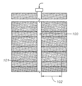
100211 Figure 1 is a schematic drawing of a wellbore used for hydraulic
fracturing
operations, wherein a viscous fluid, preferably an aqueous fluid, is injected
into the wellbore
100 at a high flow rate such that enough pressure is created inside the
wellbore to cause
fractures in the formation. Generally, the fracture produced during hydraulic
fracturing can
extend deep into the formation, as shown in the region of hydraulic fracturing
101. For
example, as shown in Figure 1, the length of the fracture 102 is shown to
extend into the
formation. In some embodiments, the length of the fracture can extend from 25
to 100 meters.
Additionally, the hydraulic fracturing process can be designed such that the
fracture extends
outward from the wellbore in multiple directions.
-4-
CA 02855730 2014-05-12
WO 2013/078306
PCT1US2012/066249
100221 Thus, provided herein are methods and compositions for the stimulation
of tight
gas wells to generate synthetic sweet spots to increase well productivity. The
methods and
compositions can, in certain embodiments, be utilized in conjunction with
standard hydraulic
fracturing techniques. For example, the well stimulation process can involve
the step of first
injecting fluid into the hole at a sufficiently high injection rate to build
enough pressure in the
wellbore, across treated formation, to initiate and propagate a hydraulic
fracture in the
referenced formation.
100231 In one embodiment, a method is provided for creating a synthetic sweet
spot within
a tight-gas formation. The method utilizes the step of injection an inventive
composition that
takes advantage of an oxidation-reduction reaction (also referred to herein as
a R.eDox
composition) for the in-situ generation of nitrogen gas within the tight gas
formation to
thereby create an area of localized pressure. By creating this area localized
pressure within
the formation, micro-fracturing of the nearby strata occurs; thereby improving
the
permeability of near fracture surface of the formation. The method can include
the step of
supplying a composition that includes compounds containing ammonium ions and
nitrite ions
to the formation, which can then react exothermically and generate gaseous
nitrogen. In
certain embodiments, all or a portion of the oxidation-reduction composition
can be
incorporated with fracturing fluids and injected during a hydraulic fracturing
treatment.
100241 Figure 2 shows the propagation of microfractures 112 within and
extending from
the fractures 114 produced as a result of the hydraulic fracturing procedure,
thus creating
sweet spots 116. Generally, depending upon the reactants and the volume of
nitrogen gas
produced therefrom, the microfractures 112 can extend throughout pseudo
fracture width 118
from the initial fracture created during hydraulic fracturing. Figure 3
similarly shows the top
view of the same.
100251 Figure 4 is another schematic demonstrating the generation of sweet
spots 116
within the formation. The figure shows the length of fracture 102 that can
extend through the
formation. . In some embodiments, this length of fracture 102 can extend up to
100 meters.
In some embodiments, this length of fracture 102 can extend up to 50 meters.
In some
embodiments, this length of fracture 102 can extend up to 25 meters. The
figure shows that
the fracture width 120 that results utilizing known fracturing techniques. In
some
embodiments, this fracture width is about 0.5 centimeters. In other
embodiments, this
fracture width is less than 0.5 centimeters. Utilizing the compositions and
methods described
herein, however, provide the surprising result of a pseudo fracture width 118,
such that a
-5-
CA 02855730 2014-05-12
WO 2013/078306
PCT1US2012/066249
sweet spot is created at and around the fracture site. In some embodiments,
this pseudo
fracture width is 1-3 meters in width.
100261 The in-situ
generation of nitrogen and heat (and resulting increase in pressure
within the formation at the reaction site), increases the permeability of
tight gas formations.
The heat and gas that are generated by the reaction can cause tensile and
thermal fractures
within the hydraulically induced and the existing fractures in the formation.
It is understood
that the generation of the microfractures within the formation may depend on
the type of
formation being treated.
100271 In certain embodiments, the method includes the steps of injecting a
reducing agent
(or reducer) and an oxidizing agent (or oxidizer) into a formation, followed
by the injection
of an activator. In certain embodiments, the activator can be an acid. In
certain
embodiments, heat can be separately or additionally supplied from the
formation or by
separate means as an activator. The base fluids (i.e., the oxidizing and
reducing agents) and
activator can be injected into the formation during hydraulic fracturing, and
enter into the
newly created hydraulic fracture. As soon as the activator has been injected
into the
formation and comes into contact with the oxidizing agent and the reducing
agent, the
oxidation/reduction reaction proceeds and large amounts of gas and heat are
generated. The
gas that is generated and the low local permeability favor an increase in pore
pressure, thus
causing the initiation of microfractures at or near the induced fracture. The
result is the
stimulation of the fracture surface, rather than damage to the formation,
which is frequently
the case during hydraulic fracturing. In may ways, the stimulation process
provided herein is
less harsh and severe than the prior art stimulation techniques, and reduces
or eliminates the
damage to the formation that is frequently encountered with the prior art
techniques. This
results in additional conductivity within the formation near the fracture.
This is an additional
advantage of the methods disclosed herein Over the prior art stimulation
methods.
100281 Figure 5 shows the predicted release of nitrogen gas within the
formation, wherein
the nitrogen gas is predicted to migrate into the fractures created within the
formation during
the hydraulic fracturing to form additional microfractures within the
formation. Referring
now to Figure 5, wellbore 104 is within formation 102. Drill pipe 106 is
positioned within
wellbore 104. Following a hydraulic fracturing process, large fractures 110
exist within
formation 102, extending outward from wellbore 104. Nitrogen gas generating
fluids, such
as a composition that includes an ammonium compound, a nitrite compound and an
activator,
are injected to the formation where it migrates within large fractures 110.
Upon reaction, the
-6-
CA 02855730 2014-05-12
WO 2013/078306
PCT1US2012/066249
injected fluids produce nitrogen gas and heat, thereby causing microfractures
112 to be
created within the formation, thereby providing pathways for the hydrocarbon
molecules
trapped within the formation to migrate and be recovered.
100291 In yet another embodiment, a composition that includes ammonium ions,
nitrite
ions, and acetic acid can be injected into a formation, wherein at least one
of the ammonium
ions and/or nitrite ions is encapsulated. It is understood that that the terms
"ammonium ions"
and "nitrite ions" as used herein refers to an ionic compound wherein a
counter ion is
included, for example, ammonium ions may be supplied as ammonium chloride.
Suitable
encapsulation materials can include hydrated polymers, such as guar, ehitosan,
and polyvinyl
alcohol. In certain embodiments, the previously noted hydrated polymer
encapsulation
materials are preferably used as the encapsulant for the nitrite ion
containing compound, such
as sodium nitrite. In alternate embodiments, binders, such as carboxymethyl
cellulose or
xanthan can be used as an encapsulant. In certain embodiments, the
carboxytnethyl cellulose
or xanthan may be preferred encapsulants for the amm.onium ion containing
compound, such
as ammonium chloride. The heat of the formation, the acid, or the aqueous
water for the
formation can all play a role in the erosion or removal of the encapsulating
material, thereby
releasing the reactants.
100301 The methods and composition described herein are responsible for the
release of
kinetic energy and thermal energy, which is a result of the exothermic nature
of the
oxidation-reduction reaction. In one embodiment, for example, aqueous
solutions of
ammonium chloride and sodium nitrite are mixed in the presence of an acid
(II') to generate
nitrogen gas, sodium chloride, water, and heat. The generation of nitrogen
gas, along with
the increased temperature, results in an increase in the local pore pressure
and the
development of microfractures in the tight formation. The balanced reaction is
provided
below. (The reaction requires the addition of acid or heat, not shown).
NH4C1+ NaNO, N2(g) + NaC1+ 2H20 + Heat (75 Kcal/mol)
100311 in typical
usage, the above noted reaction results in local generation of about 60 L
of nitrogen per one L of reactants and about 225 Kcal of heat per one L of
reactants. Without
wishing to be bound by theory, it is believed that the increased pressure and
temperature
overcome the tensile strength of the formation, thereby leading to creation of
tensile
microfractures in the formation.
-7..
CA 02855730 2014-05-12
WO 2013/078306
PCT/US2012/066249
100321 In one
embodiment, a multi-component composition that includes at least one
ammonium containing compound and at least one nitrite containing compound can
be
injected into a formation, wherein at least one component includes a polymer
coating. In
certain embodiments, the polymer coating can be hydrated to form a solid
matrix with the
component. Exemplary polymer coatings include guar, chitosan, polyvinyl
alcohol, and like
compounds. The polymer coating is operable to provide a delay in the reaction
of the
armnonium containing compound and the nitrite containing compound. In certain
embodiments, the composition can be included in an aqueous solution that is
injected into the
formation. In an alternate embodiment, the composition can be included in a
hydraulic
fracturing fluid.
100331 Figure 6 shows the generation of heat as a function of time for the
reaction of
equimolar amounts of ammonium chloride and sodium nitrite. As shown, the
temperature
rises rapidly to a peak after about 10 minutes of reaction, maintaining an
elevated
temperature for approximately 20 minutes, and slowly cooling over the next 30
minutes.
This graph demonstrates that the temperature increase as a result of the
exothermic reaction
can be designed to ensure that certain required temperatures are achieved such
that thermal
fractures are created in the formation.
100341 Figure 7 provides a graph showing the amount of pressure generated by
the
reaction of ammonium chloride and sodium nitrite. The test was run in a high
temperature,
high pressure press. Prior to initiating the reaction, the press was set at
200 psi. The reaction
showed that the pressure gradually increased by about 200 psi during the
reaction. The graph
demonstrates the increase in pressure due to the generation of nitrogen gas as
a result of the
chemical reaction. The amount of pressure that is generated is a function of
the concentration
of the reactants, allowing the reaction to be tailored to achieve certain
pressures sufficient to
create tensile fractures within the formation.
100351 In an alternate embodiment, a multi-component composition that includes
at least
one ammonium containing compound and at least one nitrite containing compound
can be
injected into a formation, wherein at least one component can be encapsulated
with a binder
to form a solid matrix with the component. Exemplary encapsulating binders
include 55-
carboxymethyl cellulose, xanthan, and like compounds. Exemplary binders are
preferably
reactive with acid, water and/or heat such that upon contact with acid or
water or upon
heating, the binder erodes or dissolves, thereby allowing the reactants to
react.
-8-
CA 02855730 2014-05-12
WO 2013/078306
PCT1US2012/066249
100361 In another
embodiment, a fracturing fluid, optionally including a proppant
suspended therein, can be injected into a formation. Following injection of
the fracturing
fluid, a composition that includes at least one amrn.onium containing
compound, at least one
nitrite containing compound and an acid, for example acetic acid, can be
injected into the
formation. At least one of the ammonium ions and nitrite ions is encapsulated.
In certain
embodiments, a solution that includes the ammonium and nitrite ion containing
composition
can be injected directly into the formation after the fracturing fluids have
been injected. In
alternate embodiments, the ammonium and nitrite ion containing solution can be
injected into
the formation approximately 15 minutes after the completion of the injection
of the fracturing
fluid injection, alternatively approximately 30 minutes after the completion
of the injection,
alternatively approximately 1 hour after the completion of the injection. The
acid and/or the
heat of the formation can erode the encapsulating material such that the
reaction between the
ammonium and nitrite containing compounds is delayed, thereby allowing the
reactants to
migrate and seep into the fractures within the formation.
100371 In another embodiment, an aqueous composition that includes ammonium
ions,
nitrite ions, and a buffer are injected into a formation in a hydraulic
fracturing procedure.
The buffer preferably is soluble and compatible with the ammonium and nitrite
containing
compounds, and the resulting reaction products. Additionally, the buffer
preferably releases
acidic hydrogen ions at a rate that is sufficiently slow such that the
injected fluids have time
to enter into the formation, and migrate into the fractures created by the
hydraulic fracturing
process before the pH is reduced to a value of less than about 7 and the
reaction proceeds.
Exemplary buffers can include acetates, including methyl acetates and ethyl
acetates. The
initial pH of the aqueous solution is around 7. At typical formation
temperatures, methyl
acetate degrades and releases acetic acid. This takes place deep inside the
formation, after
injection of the fluids. In certain embodiments, approximately 5% by volume of
the buffer
(0.1 molar solution) can be included with the reactants. The buffer acts as
the activator, when
it degrades and releases acetic acid within the formation. At lower
temperatures, for example
between about 60-70 C, acidic hydrogen atoms at a pH of between about 3 and 5
can activate
the reaction. In some embodiments, the aqueous composition that includes
ammonium ions,
nitrite ions, and a buffer is included with a fracturing fluid and injected
into a formation in a
hydraulic fracturing procedure.
100381 For each of the embodiments described herein, exemplary ammonium ions
include
ammonium hydroxide, ammonium chloride, ammonium bromide, ammonium nitrate,
-9-
CA 02855730 2014-05-12
WO 2013/078306
PCT1US2012/066249
anunonium nitrite, ammonium sulfate, ammonium carbonate, ammonium hydroxide,
urea,
and the like.
100391 Exemplary nitrite ions include sodium nitrite, potassium nitrite,
sodium
hypochlorite, and the like.
100401 Exemplary ammonium-nitrite combinations for use herein can include,
urea-
sodium hypochlorite; urea-sodium nitrite; ammonium hydroxide-sodium
hypochlorite;
ammonium chloride-sodium nitrite, and the like. In certain embodiments,
ammonium nitrite
can be used as the reactant, wherein encapsulated ammonium nitrite is injected
into the
formation, wherein it contacts an acid, thereby leading to the reaction of the
components and
the generation of the desired nitrogen gas.
100411 In certain embodiments, equal molar amounts of the ammonium containing
compound and the nitrite containing compound arc supplied to the formation to
ensure
complete reaction of both components. In alternate embodiments, up to about a
5% excess of
either component can be employed, however it is generally preferred that
equimolar amounts
are employed. Thus, in certain embodiments, the ratio of ammonium to nitrite
in the
compositions disclosed herein can range from between about 1.1:1 to 1:1.1;
alternatively
between about 1.05:1 and 1:1.05, alternatively about 1:1.
100421 Exemplary acids that can be used as the activator for the reaction
include weak
acids, such as acetic acid. citric acid and the like, strong acids, such as
hydrochloric acid and
the like, and diluted strong acids. In general, any compound that is capable
of releasing an
acidic hydrogen can be used as the activator. In certain preferred
embodiments, acetic acid is
used as the activator. In certain embodiments, a 0.1 molar solution of acetic
acid having a
concentration of about 0.5% by volume (of the total volume) can be utilized,
hi certain
embodiments, dilute weak acids, such as dilute hydrochloric acid, can be used
to activate the
reaction, with or without the addition of a buffer. One main advantage to the
use of dilute
strong acids is increased control over the reaction.
100431 In certain
embodiments, the procedures described herein can utilize the elevated
temperatures within the formation as the activator or co-activator (along with
the acid or
other hydrogen releasing compound) for the reaction. For example, in certain
embodiments,
the temperature within the formation may be about 200 C. In certain
embodiments, a
temperature of at least about 60 C, alternatively at a temperature of at least
about 70 C. in
certain embodiments, the temperature is between about 60 C and 70 C,
alternatively the
-10-
CA 02855730 2014-05-12
WO 2013/078306
PCT1US2012/066249
temperature is between about 65'C and 80"C is desired. As noted above, in
certain
embodiments wherein the temperature of the formation is used to activate or
initiate the
reaction, a buffer can be employed such that acidic hydrogen ions arc released
slowly.
100441 In certain
embodiments, the fluids used in this application can include certain
chemical additives that can help to form a viscous fracturing fluid. The
chemical additives
can include at least one solvent and at least one polymer that is soluble in
the solvent. The
total composition of the fracturing fluid can also include a reducing agent,
an oxidizing agent,
and an activator. The solvent can also include water and/or a surfactant,
depending on the
type of formation being treated. The oxidizing agent can be an ammonium
containing
compound, such as ammonium chloride, and the reducing agent can be a nitrite
containing
compounds, such as sodium nitrite. The activator can be an acid, such as
hydrochloric acid
or acetic acid. The polymer can be mixed with the solvent or water to form a
viscous fluid.
Exemplary polymers that can be used include guar and carboxymethyl cellulose.
The
polymer can be used to coat at least one of the reactants, for example
ammonium chloride, to
prevent premature reaction and to also provide addition viscosity to the
fluid. The oxidizing
agent and the reducing agent, however, can still be injected into the
formation separately at a
later stage after the viscous polymer containing solution is injected for
purposes of fracturing.
Following injection of the oxidizing and reducing agents, the initiator can be
injected to
trigger the reaction and thereby create a synthetic sweet spot. The created
synthetic sweet
spot will have higher pressure than surrounding formation rock, but the
pressure that is
generated will be at least partially consumed to generate fractures in the
formation. If the
pressure was not high enough to break the formation, however, then the local
increase in
pressure is analogous to a sweet spot itself, because the increase in pressure
will assist in
producing the reservoir hydrocarbon. The main intention of the methods and
compositions
described herein, however, is to generate sufficient pressure to cause microfi-
actures, thereby
increasing the porosity and permeability of formation.
100451 Generally,
during successful hydraulic fracturing procedures, the fracturing liquid
must be removed from the well upon completion of the stimulation treatment.
The process
can be both costly and time consuming. Advantageously, the compositions and
methods
described herein are designed to cause no damage to the formation, which is a
challenge
considering the current fracturing technologies. To overcome this problem, the
compositions
and methods described herein advantageously utilize novel combinations of
nitrogen
generating chemicals as the hydraulic fracturing liquid-base. Thus, in certain
embodiments,
-11-
CA 02855730 2014-05-12
WO 2013/078306
PCT/US2012/066249
the liquids used for fracturing of the formation, which can include the
nitrogen generating
chemicals previously described, can be injected into the formation though the
wellbore or
other injection means at a sufficiently high injection rate so as to create
pressures within the
formation that can effectively fracture the rock or open previously existing
fractures. As the
fracturing liquid seeps into the formation, these nitrogen generating
chemicals can be
triggered to react, thereby generating large amounts of nitrogen gas and heat
within the
formation and near the newly created fracture surfaces. In certain
embodiments, the
triggering mechanism can be the heat of the formation temperature. In
alternate
embodiments, the triggering mechanism can be an injected fluid, such as an
acid, that can be
injected at the end of the fracturing process. The generated nitrogen gas and
heat can create
additional microfractures and thermal fractures at or near the fracture formed
as a result of
the hydraulic fracturing. The reaction generates at least about 200 Kcal and
50 L of nitrogen
gas per liter of the nitrogen generating chemicals that is supplied to the
reaction, alternatively
about 225 Kcal and 60 L of nitrogen per liter of the nitrogen generating
chemicals supplied to
the reaction.
100461 In certain embodiments, a polymer can be mixed with ammonium solution,
nitrite
solution, or a combination thereof, and can serve as the base fluid being
injected in the
formation. Generally, the injection of the base fluid is followed by the
injection of an acid,
such as hydrochloric or acetic acid. Thus, in certain embodiments, the
hydraulic fracturing
fluid can include a solvent base, such as water, a polymer viscosifying agent,
and an
ammonium containing compound. In such an embodiment, following the injection
of the
fracturing fluid, a nitrite containing compound and activator would be
injected into the
formation, either in a single injection, or in series (i.e., the nitrite
containing compound would
be injected, followed by the injection of the initiator).
100471 in an
alternate embodiment, a hydraulic fracturing fluid can include a solvent base,
such as water, a polymer viscosifying agent, and a nitrite containing
compound. In such an
embodiment, following the injection of the fracturing fluid, an ammonium
containing
compound and activator would then be injected into the formation, either in a
single injection,
or in series (i.e., the ammonium containing compound would be injected into
the formation
first, followed by the injection of the initiator).
100481 In certain embodiments, the acetic acid concentration can be between
about 0.5 and
vol.% of the total volume of fluids being injected into the formation. The
acetic acid
concentration can range from about 0.5 to I molar, such that the solution pH
is between about
-12-
CA 02855730 2014-05-12
WO 2013/078306
PCT1US2012/066249
3 and 5. The ratio of ammonium chloride to sodium nitrite can be between about
1:2 and 2:1,
alternatively between about 1:1.5 and 1.5:1, alternatively between about
1:1.25 and 1.25:1,
alternatively about 1:1. In certain embodiments the ratio of ammonium chloride
to sodium
nitrite can be between about 1:1 and 2:1, alternatively between about 1:1 and
1.5:1,
alternatively between about 1.25:1. The mixture of nitrogen generating
compounds can make
up to about 50% by volume of the total fluid volume, alternatively up to about
40%,
alternatively up to about 30%, alternatively up to about 20%. The reaction can
occur at any
concentration of reactants, however in certain embodiments, the molarity of
the ammonium
chloride and sodium nitrite can range between about 2 and 10 molar,
alternatively between
about 2 and 5 molar, or alternatively between about 5 and 10 molar. The
mixture of nitrogen
generating compounds can be up to about 40% by volume of the total volume of
fluids being
injected, alternatively up to about 50% of the total volume, alternatively up
to about 60%. In
certain embodiments, the remainder of the volume can be water. In certain
embodiments, the
composition includes at least about 40% by volume water, alternatively at
least about 50% by
volume water, alternatively at least about 60% by volume, alternatively at
least about 70% by
volume water. In certain embodiments, additional additives can be added to the
composition,
for example, surfactants, iron control (citric acid), friction reducers, and
the like. The
fracturing fluids can be water-based, oil-based, or foam based (i.e., liquid
and gas) fracturing
fluids. The encapsulated reactants can he added to any of the above fracturing
fluids.
100491
Advantageously, in contrast to some currently employed stimulation methods,
the
methods and compositions described herein do not produce any damaging by-
products as a
result of the in-situ reaction. For example, the acids utilized as activators
are typically
consumed by the reaction and are only present in relatively small quantities
such that there is
little or no residual acid remaining that may cause environmental concerns. As
a result,
following the stimulation procedure, no clean-up procedure is required. Thus,
through the
creation of the synthetic sweet spots, maximum enhancement of gas production
with a
minimal creation of damaging waste products is provided.
100501 In certain embodiments, the methods and compositions described herein
advantageously and unexpectedly reduce or eliminate formation damage that can
be caused
by a fracturing gel, water blockage, and/or condensate banldng. These
conditions result in
reduced permeability of fluids within the formation, and subsequently lead to
poor production
of a well. The generation of the synthetic sweet spot according to the methods
described
herein avoids these problems.
-13-
CA 02855730 2014-05-12
WO 2013/078306
PCT1US2012/066249
100511 In certain embodiments, the methods and compositions described herein
advantageously and unexpectedly create synthetic sweet spots in tight-gas
reservoirs that lack
the presence of such important flow-supporting stratas. As noted previously, a
sweet spot is
an area of maximum production within a formation. These formations lack the
pathways that
allow for the flow of hydrocarbon fluids and gases to a point of production.
100521 The methods and compositions provided herein solve several problems
that are
frequently encountered during the construction of commercial wells in tight-
gas reservoirs.
100531 First, problems associated with damage to the formation caused by
current
hydraulic fracturing methods can be reduced or eliminated. For example, the
methods and
compositions described herein, advantageously help to reduce or eliminate
fracturing-fluid
filtrate that can be locked near a recently created fracture surface by
creating many tensile
fractures near the fracture surface such that any filtrate readily flows
through these fractures
toward the well.
100541 Second, the methods and compositions provided herein, advantageously
enhance
production over traditional hydraulic fracturing methods through the creation
of
microfractures, which provide additional conductivity to the near fracture
surface such that it
provides new channels for gas to flow toward the created fracture. The
additional reservoir
volume contacting the well contributes significantly to the overall flow
efficiency of the
drainage area being affected by the induced fracture.
100551 Finally,
current hydraulic fracturing techniques that require many fracturing stages
to create sufficient reservoir volume contact within the well to be commercial
are eliminated
as a result of the production of microfractures due to the gas and heat that
are produced. By
reducing the number of required fracturing stages for same production, the
present
stimulation treatment described herein is both more cost effective and
accomplished more
quickly, thereby providing viable economical options for the stimulation of
low producing
wells.
100561 Figure 8 provides a graph showing the increase in cumulative pore
volume of the
formation (cm3) as a function of pressure. A core flood test of the nitrogen
generating
compounds in a carbonate core was performed. Pressure across the core prior to
the
generation of the synthetic sweet spot was approximately 15 psi and the
permeability (Kb)
was about 3.7 md. After nitrogen generation (i.e., the synthetic generation of
a sweet spot in
the core sample) pressure across the core was approximately 0 psi, and
permeability (Ktnine)
-14-
increased to about 982.2 md. As brine permeability increased, the pressure
drop across the
tested core sample was reduced from about 15 psi to 0 psi, indicating an
increase in the core
permeability and porosity, thus signaling the creation of a sweet spot.
[0057] The testing procedure for determining the creation of a sweet
spot proceeds as
follows. The Cordload testing device was designed such that the tested core
sample has two
inlet lines and one outlet lines. Each inlet line has its own pump and feed
container. The
core was evacuated of air by administering a saturated brine solution (7
,Aft(Vii NaCI). The
core was then loaded into the core holder. Approximately 3000 psi confining
stress pressure
was applied and 500 psi backpressure was maintained. The temperature was
raised to about
200 F. A 7 wt% sodium chloride brine solution was injected in the pre-
designated
production direction until a stable differential pressure was obtained. The
absolute
permeability to brine was then calculated. A mixture of ammonium chloride (2
molar) and
acetic acid (1 molar) was injected into the core sample from one inlet, and at
the same time
sodium nitrate (2 molar) was injected from the other inlet, such that both
solutions meet at the
inlet of the core sample. A 7 wt% sodium chloride brine solution was then
injected at a
constant rate and measure absolute permeability to brine.
[0058] Although the present invention has been described in detail, it
should be
understood that various changes, substitutions, and alterations can be made
hereupon without
departing from the principle and scope of the invention. Accordingly, the
scope of the
present invention should be determined by the following claims and their
appropriate legal
equivalents.
[0059] The singular forms "a", "an" and "the" include plural referents,
unless the context
clearly dictates otherwise.
100601 Optional or optionally means that the subsequently described event or
circumstances may or may not occur. The description includes instances where
the event or
circumstance occurs and instances where it does not occur.
[0061] Ranges may be expressed herein as from about one particular value,
and/or to
about another particular value. When such a range is expressed, it is to be
understood that
another embodiment is from the one particular value and/or to the other
particular value,
along with all combinations within said range.
-15--
CA 2855730 2018-05-28
. =
[0062] As used herein and in the appended claims, the words "comprise," "has,"
and
"include" and all grammatical variations thereof are each intended to have an
open, non-
limiting meaning that does not exclude additional elements or steps.
10063] As used herein, terms such as "first" and "second" are arbitrarily
assigned and are
merely intended to differentiate between two or more components of an
apparatus. It is to be
understood that the words "first" and "second" serve no other purpose and are
not part of the
name or description of the component, nor do they necessarily define a
relative location or
position of the component. Furthermore, it is to be understood that that the
mere use of the
twit "first" and "second" does not require that there be any "third"
component, although that
possibility is contemplated under the scope of the present invention.
I 6-
CA 2855730 2018-05-28