Note: Descriptions are shown in the official language in which they were submitted.
STAY-IN PLACE FORMWORK WITH ENGAGING AND ABUTTING
CONNECTIONS
Technical Field
[0001] The technology disclosed herein relates to formwork for fabricating
structural
parts of buildings, tanks and/or other structures out of concrete or other
similar curable
construction materials. Particular embodiments of the invention provide
connector
components for modular formworks and methods for providing connections between
modular formwork units.
Background
[0002] Any discussion of the prior art throughout the specification should in
no way be
considered as an admission that such prior art is widely known or forms part
of general
common knowledge in the field.
[0003] It is known to fabricate structural parts for buildings, tanks or the
like from
concrete using modular stay-in-place formworks. Such structural parts may
include walls,
ceilings or the like. Examples of such modular stay in place formworks include
those
described US patent publication No. 2005/0016103 (Piccone) and PCT publication
No.
W096/07799 (Sterling). A representative drawing depicting a partial formwork
28
according to one prior art system is shown in top plan view in Figure 1.
Formwork 28
includes a plurality of wall panels 30 (e.g. 30A, 30B, 30D), each of which has
an
inwardly facing surface 31A and an outwardly facing surface 31B. Each of
panels 30
includes a terminal male T-connector component 34 at one of its transverse,
vertically-
extending edges (vertical being the direction into and out of the Figure 1
page) and a
terminal female C-connector component 32 at its opposing vertical edge. Male T-
connector components 34 slide vertically into the receptacles of female C-
connector
components 32 to join edge-adjacent panels 30 and to thereby provide a pair of
substantially parallel wall segments (generally indicated at 27, 29).
Depending on the
needs for particular wall segments 27, 29, different panels 30 may have
different
1
CA 2855742 2019-03-08
CA 02855742 2014-05-13
WO 2013/075251
PCT/CA2012/050850
transverse dimensions. For example, comparing panels 30A and 30B, it can be
seen that
panel 30A has approximately 1/4 of the transverse length of panel 30B.
[0005] Formwork 28 includes support panels 36A which extend between, and
connect to
each of, wall segments 27, 29 at transversely spaced apart locations. Support
panels 36A
.. include male T-connector components 42 slidably received in the receptacles
of female
C-connector components 38 which extend inwardly from inwardly facing surfaces
31A
or from female C-connector components 32. Formwork 28 comprises tensioning
panels
40 which extend between panels 30 and support panels 36A at various locations
within
formwork 28. Tensioning panels 40 include male T-connector components 46
received in
the receptacles of female C-connector components 38.
[0006] In use, formwork 28 is assembled by slidable connection of the various
male T-
connector components 34, 42, 46 in the receptacles of the various female C-
connectors
32, 38. Liquid concrete is then poured into formwork 28 between wall segments
27, 29.
The concrete flows through apertures (not shown) in support panels 36 and
tensioning
panels 40 to fill the inward portion of formwork 28 (i.e. between wall
segments 27, 29).
When the concrete solidifies, the concrete (together with formwork 28) may
provide a
structural component (e.g. a wall) for a building or other structure.
[0007] A known problem with prior art systems is referred to colloquially as
"unzipping". Unzipping refers to the separation of connector components from
one
another due to the weight and/or outward pressure generated by liquid concrete
when it is
poured into formwork 28. By way of example, unzipping may occur at connector
components 32, 34 between panels 30. Figure 2 schematically depicts the
unzipping of a
prior art connection 50 between male T-connector component 34 and
corresponding
female C-connector component 32 at the edges of a pair of edge-adjacent panels
30. The
concrete (not explicitly shown) on the inside 51 of connection 50 exerts
outward forces
on panels 50 (as shown at arrows 52, 54). These outward forces tend to cause
deformation of the connector components 32, 34. In the Figure 2 example
illustration,
connector components 32, 34 exhibit deformation in the region of reference
numerals 56,
58, 60, 62, 64, 68. This deformation of connector components 32, 34 may be
referred to
as unzipping.
2
CA 02855742 2014-05-13
WO 2013/075251
PCT/CA2012/050850
[0008] Unzipping of connector components can lead to a number of problems. In
addition to the unattractive appearance of unzipped connector components,
unzipping can
lead to separation of male connector components 34 from female connector
components
32. To counteract this problem, prior art systems typically incorporate
support panels
36A and tensioning panels 40, as described above. However, support panels 36A
and
tensioning panels 40 may not completely eliminate the unzipping problem.
Notwithstanding the presence of support panels 36A and tensioning panels 40,
in cases
where male connector components 34 do not separate completely from female
connector
components 32, unzipping of connector components 32, 34 may still lead to the
formation of small spaces (e.g. spaces 70, 71) or the like between connector
components
32, 34. Such spaces can be difficult to clean and can represent regions for
the
proliferation of bacteria or other contaminants and can thereby prevent or
discourage the
use of formwork 28 for particular applications, such as those associated with
food storage
or handling or other applications requiring sanitary conditions or the like.
Such spaces
can also permit the leakage of liquids and/or gasses between inside 51 and
outside 53 of
panels 30. Such leakage can prevent or discourage the use of formwork 28 for
applications where it is required that formwork 28 be impermeable to gases or
liquids
(e.g. to provide the walls of tanks used to store water or other liquids).
Such leakage can
also lead to unsanitary conditions on the inside of formwork 28 and/or cause
or lead to
corrosion of reinforcement bars (rebar) used in the concrete structure.
[0009] In some applications (e.g. in the walls of tanks used to store water or
other fluids),
there is a desire to maintain a fluid-tight seal at connections between
connector
components (e.g. connector components 32, 34). Most prior art systems do not
provide
fluid-tight seals between connector components. Those prior art systems that
do provide
fluid tight seals can be difficult to work with because of difficulties
associated with
making and breaking the fluid-tight connections between connector components
(which
can be desirable during assembly of a formwork or fabrication of a
corresponding
structure).
[0010] Also, some prior art formwork systems can be difficult to assemble. For
example,
some prior art formwork systems involve making connections by initially
orienting the
3
CA 02855742 2014-05-13
WO 2013/075251
PCT/CA2012/050850
panels at relatively large angles (e.g. orthogonal angles) relative to one
another. Again,
this can be difficult or impossible in some constrained spaces.
[0011] The foregoing examples of the related art and limitations related
thereto are
intended to be illustrative and not exclusive. Other limitations of the
related art will
become apparent to those of skill in the art upon a reading of the
specification and a study
of the drawings.
[0012] There remains a general need for effective apparatus and methods for
modular
formwork systems.
Summary
[0013] The following embodiments and aspects thereof are described and
illustrated in
conjunction with systems, tools and methods which are meant to be exemplary
and
illustrative, not limiting in scope. In various embodiments, one or more of
the above-
described problems have been reduced or eliminated, while other embodiments
are
directed to other improvements.
[0014] One aspect of the invention provides a formwork assembly comprising a
plurality
of elongated panels connectable to one another in edge-adjacent relationship.
The
plurality of panels comprises first and second edge-adjacent panels
connectable to one
another at a connection between a male connector component of the first panel
and a
female connector component of the second panel. The female connector component
comprises a female engagement portion which defines a principal receptacle and
the male
connector component comprises a male engagement portion which is received in
the
principal receptacle to form the connection. The female connector component
comprises
a first abutment portion and the male connector component comprises a second
abutment
portion which abuts against the first abutment portion to form the connection.
The first
and second abutment portions comprise corresponding first and second abutment
surfaces
which are bevelled with respect to outer surfaces of the first and second edge-
adjacent
panels.
[0015] In addition to the exemplary aspects and embodiments described above,
further
aspects and embodiments will become apparent by reference to the drawings and
by
study of the following detailed descriptions.
4
CA 02855742 2014-05-13
WO 2013/075251
PCT/CA2012/050850
Brief Description of Drawings
[0016] Exemplary embodiments are illustrated in referenced figures of the
drawings. It is
intended that the embodiments and figures disclosed herein are to be
considered
illustrative rather than restrictive.
[0017] In drawings which illustrate non-limiting embodiments of the invention:
Figure 1 is a is a top plan view of a prior art modular stay-in-place
formwork;
Figure 2 is a magnified partial top plan view of the Figure 1 formwork,
showing
the unzipping of a connection between wall panels;
Figure 3A is a partial cross-sectional view of a modular stay-in-place
formwork
according to a particular embodiment;
Figures 3B and 3C are isometric views of the panels of the Figure 3A formwork;
Figure 3D is an isometric view of a support member of the Figure 3A formwork;
Figures 4A-4D show schematic views of a method for making connection
between the complementary connector components of a pair of edge-adjacent
panels of
the Figure 1 formwork;
Figures 4E and 4F are magnified partial cross-sectional views of the Figure 3A
formwork showing a connection between edge-adjacent panels:
Figures 5A and 5B respectively show enlarged partial plan views of a loose-fit
connection and a completed connection between a pair of edge-adjacent panels
and their
respective connector components according to another embodiment;
Figures 6A and 6B respectively show enlarged partial plan views of a loose-fit
connection and a completed connection between a pair of edge-adjacent panels
and their
respective connector components according to another embodiment;
Figure 7A-7D are enlarged partial plan views of connections between connector
components of pairs of edge-adjacent panels according to other example
embodiments;
Figures 8A and 8B are partial cross-sectional views of portions of modular
stay-
in-place formworks according to other example embodiments; and
Figures 9A and 9B are partial cross-sectional views of portions of modular
stay-
in-place formworks according to other example embodiments
5
CA 02855742 2014-05-13
WO 2013/075251
PCT/CA2012/050850
Description
[0018] Throughout the following description specific details are set forth in
order to
provide a more thorough understanding to persons skilled in the art. However,
well
known elements may not have been shown or described in detail to avoid
unnecessarily
obscuring the disclosure. Accordingly, the description and drawings are to be
regarded in
an illustrative, rather than a restrictive, sense.
[0019] Particular embodiments of the invention provide formwork assemblies
comprising
a plurality of elongated panels connectable to one another in edge-adjacent
relationship.
The plurality of panels comprises first and second edge-adjacent panels
connectable to
one another at a connection between a male connector component of the first
panel and a
female connector component of the second panel. The female connector component
comprises a female engagement portion which defines a principal receptacle and
the male
connector component comprises a male engagement portion which is received in
the
principal receptacle to form the connection. The female connector component
comprises
a first abutment portion and the male connector component comprises a second
abutment
portion which abuts against the first abutment portion to form the connection.
The first
and second abutment portions comprise corresponding first and second abutment
surfaces
which are bevelled with respect to outer surfaces of the first and second edge-
adjacent
panels.
[0020] Figure 3A is a partial cross-sectional view of a modular stay-in-place
formwork
128 according to a particular embodiment of the invention which may be used to
fabricate a portion of a wall of a building or other structure. Formwork 128
of the Figure
3A embodiment includes panels 130. 133 and support members 136 which are
connected
to one another to provide wall segments 127, 129 which, in the illustrated
embodiment,
extend in the vertical direction (into and out of the page in the Figure 3A
view) and in the
transverse direction 17. The components of formwork 128 (i.e. panels 130, 133
and
support members 136) are preferably fabricated from a lightweight and
resiliently
deformable material (e.g. a suitable plastic) using an extrusion process. By
way of non-
limiting example, suitable plastics include: poly-vinyl chloride (PVC),
acrylonitrile
butadiene styrene (ABS) or the like. In other embodiments, the components of
formwork
128 may be fabricated from other suitable materials, such as steel or other
suitable alloys,
6
CA 02855742 2014-05-13
WO 2013/075251
PCT/CA2012/050850
for example. Although extrusion is the currently preferred technique for
fabricating the
components of formwork 128, other suitable fabrication techniques, such as
injection
molding, stamping, sheet metal fabrication techniques or the like may
additionally or
alternatively be used.
[0021] Formwork 128 comprises a plurality of panels 130, 133 which are
elongated in
the vertical direction (i.e. the direction into and out of the page of Figure
3A and shown
by double-headed arrows 19 in Figures 3B and 3C) and which extend in
transverse
directions 17. Panels 130, 133 respectively comprise outward facing (exterior)
surfaces
131A, 135A and inward facing (interior) surfaces 131B, 135B. In the
illustrated
embodiment, exterior surfaces 131A, 135A are substantially flat, although in
other
embodiments, exterior surfaces 131A, 135A may be provided with desired shapes
(e.g.
corrugation or the like). Interior surfaces 131B. 135B comprise a number of
features
described in more detail below.
[0022] In the illustrated embodiment, panels 130, 133 have a substantially
uniform cross-
section along their entire vertical length, although this is not necessary. In
the illustrated
embodiment, the transverse dimensions (direction 17) of panels 130, 133 are
the same for
each of panels 130, 133. This is not necessary. In general, it can be
desirable to fabricate
panels 130, 133 having a number of different transverse dimensions which may
suit
particular applications. By way of non-limiting example, panels 130. 133 may
be
.. provided with 2, 3, 4 and 6 inch transverse dimensions or such other
transverse
dimensions as may be appropriate or desirable for particular applications. In
some
embodiments, panels 130, 133 are prefabricated to have a variety of different
vertical
dimensions with may be suitable for a variety of different applications. In
other
embodiments, the vertical dimensions of panels 130, 133 may be made
arbitrarily and
.. then panels 130, 133 may be cut to length for different applications.
Preferably, panels
130, 133 are relatively thin in the inward-outward direction (shown by double-
headed
arrow 15 of Figure 3A) in comparison to the inward-outward dimension of the
resultant
walls fabricated using formwork 128. In some embodiments, the ratio of the
inward-
outward dimension of a structure formed by formwork 128 to the inward-outward
dimension of a panel 130, 133 is in a range of 10-600. In some embodiments,
the ratio of
7
CA 02855742 2014-05-13
WO 2013/075251
PCT/CA2012/050850
the inward-outward dimension of a structure formed by formwork 128 to the
inward-
outward dimension of a panel 130, 133 is in a range of 20-300.
[0023] In the Figure 3A embodiment, panels 130, 133 are different from one
another in
the manner that edge-adjacent panels 130, 133 connect to one another to
provide wall
segments 127, 129. In other embodiments, both wall segments 127, 129 may be
comprise
the same types of panels. For example, wall segment 129 may be provided by
panels 133
in the place of panels 130.
[0024] Panels 133 incorporate first, generally female, connector components
132 at one
of their transverse edges and second, generally male, connector components 134
at their
opposing transverse edges. As shown in Figure 3A and explained further below,
connector components 132, 134 are complementary to one another such that
connector
components 132, 134 of edge-adjacent panels 133 may be joined together to form
connections 150 between edge-adjacent panels 133. Panels 133 may be connected
in
edge-adjacent relationship to provide wall segment 127.
[0025] Panels 130 of the illustrated embodiment incorporate generally C-
shaped, female
connector components 137 at both of their transverse edges. Connector
components 137
are connected to complementary T-shaped, male connector components 139 at the
inner
or outer edges of support members 136 so as to form connections 140 which
connect
panels 130 in edge-adjacent relationship and to thereby provide wall segment
129.
Connector components 137 of panels 130 and connector components 139 of support
members 136 may be connected to one another by slidably inserting male
connector
components 139 into female connector components 137. In other embodiments,
connector components 137, 139 may be different than those shown in the
illustrated
embodiment and may connect to one using techniques other than relative
sliding, such as,
by way of non-limiting example, deformable "snap-together" connections,
pivotal
connections, push on connections and/or the like. In some embodiments, panels
130 may
be provided with male connector component and support members 136 may comprise
female connector components.
[0026] Figure 3D shows a support member 136 according to a particular
embodiment.
Support members 136 comprise a number of apertures 141. 143 which permit a
flow of
liquid concrete therethrough. As mentioned above, support member 136 comprises
a pair
8
CA 02855742 2014-05-13
WO 2013/075251
PCT/CA2012/050850
of connector components 139 at each of its inner and outer edges. In the
illustrated
embodiment, connector components 139 each comprise male, T-shaped connector
components. Like panels 130, 133, support members 136 may be fabricated to
have a
number of vertical lengths or may be cut to desired lengths. Further, support
members
136 may be made to have different width dimensions (see arrow 15 of Figure 3A)
so as to
provide formwork 128 with different width dimensions. suitable for different
applications.
[0027] Panels 133 comprise a connector component 142 which is complementary to
the
pair of connector components 139 of support members 136. In the illustrated
embodiment, connector components 142 of panels 133 comprise "double-J" shaped,
female connector components that slidably receive T-shaped connector
components 139
of support members 136 to provide connections 145 between support members 136
and
panels 133. In other embodiments, connector components 139. 142 may be
different than
those shown in the illustrated embodiment and may connect to one using
techniques other
than relative sliding, such as, by way of non-limiting example, deformable
"snap-
together" connections, pivotal connections, push on connections and/or the
like. In some
embodiments, panels 133 may be provided with male connector component and
support
members 136 may comprise female connector components.
[0028] Connector components 142 may be located relatively close to one of the
transverse edges of panels 133. In the illustrated embodiment. connector
components 142
are located relatively close to the transverse edges of panels 133 which
include connector
components 132. In the particular case of the illustrated embodiment,
connector
components 142 are immediately adjacent connector components 132 and connector
components 142, 132 share a connector wall portion 167 with one another. The
proximity
of connector components 142 to one of the transverse edges of panels 133 means
that
connections 145 between panels 133 and support members 136 are also located
relatively
close to one of the transverse edges of panels 133, such that support members
136
reinforce connections 150 between edge-adjacent panels 133.
[0029] Support members 136 may also optionally be connected to panels 130, 133
at
locations away from their transverse edges, as is shown in the Figure 3A
embodiment. In
the Figure 3A embodiment, panels 133 comprise interior connector components
144
9
CA 02855742 2014-05-13
WO 2013/075251
PCT/CA2012/050850
which are complementary to a pair of connector components 139 on the edges of
support
panels 136 and panels 130 comprise interior connector components 146 which are
complementary to a pair of connector components 139 on the edges of support
panels
136. In the illustrated embodiment, interior connector components 144. 146
comprise
"double-J" shaped, female connector components that slidably receive T-shaped
connector components 139 of support members 136. In other embodiments,
connector
components 139, 144, 146 may be different than those shown in the illustrated
embodiment and may connect to one using techniques other than relative
sliding, such as,
by way of non-limiting example, deformable "snap-together" connections,
pivotal
connections, push on connections and/or the like. In some embodiments, panels
133, 130
may be provided with male connector component and support members 136 may
comprise female connector components.
[0030] In the illustrated embodiment, panels 133, 130 respectively comprise
one interior
connector component 144, 146 which is generally centrally located along the
transverse
dimension of panels 133. 130. In other embodiments, panels 133, 130 may be
provided
with different numbers (e.g. zero or a plurality) of interior connector
components 144,
146 which may depend on the transverse (direction 17) width of panels 133, 130
and/or
the strength requirements of a particular application. It will be understood
that the mere
provision of connector components 144, 146 on panels 133, 130 does not mean
that
support members 136 must be connected to these panels.
[0031] Figures 4A-4D show schematic views of a method for making a connection
150
between female connector component 132 and male connector component 134 of
edge
adjacent panels 133 of formwork 128. In the illustrated embodiment. connection
150 may
be formed between edge-adjacent panels 133A, 133B by positioning panels 133A,
133B
so that their complementary connector components 132, 134 are aligned with one
another
at an oblique angle (Figure 4A), moving panels 133A, 133B relative to one
another in
direction 19 such that complementary connector components 132, 134 slideably
engage
one another in a relatively loose-fit connection 180 (Figure 4B), continuing
to move
panels 133A, 133B relative to one another at the oblique angle with connector
components 132, 134 in loose-fit connection 180 until panels 133A, 133B are
aligned in
direction 19 (Figure 4C) and then pivoting panels 133A, 133B relative to one
another
CA 02855742 2014-05-13
WO 2013/075251
PCT/CA2012/050850
about an axis generally parallel with direction 19 to move panels 133A, 133B
into a
generally flattened orientation (Figure 4D). It will be appreciated that while
described as
a vertical direction, direction 19 may generally be any direction depending on
the desired
orientation of panels 133A, 133B during assembly. Panels 133A, 133B may be
engaged
in loose-fit connection 180 (Figure 4B) by insertion of male connector
component 134
into female connector component 132 at an end 117 of panel 133A, for example.
[0032] Figures 4E and 4F respectively show enlarged partial plan views of
connector
components 132, 134 when edge-adjacent panels 133A, 133B in the loose-fit
connection
180 (Figure 4C) and when edge-adjacent panels 133A, 133B have been flattened
to
provide connection 150 (Figure 4D). Each of connector components 132, 134
comprises
an engagement portion and an abutment portion. More particularly, female
connector
component 132 comprises an engagement portion 182 and an abutment portion 184
and
male connector component 134 comprises an engagement portion 186 and an
abutment
portion 188. When connector components 132, 134 are in loose-fit connection
180 of
Figure 4E, engagement portions 182, 186 of connector components 132, 134 are
engaged
with one another, but there is no substantial contact or friction between
abutment portions
184, 188. When connector components 132, 134 are moved into connection 150.
engagement portions 182, 186 remain engaged with one another, but abutment
portions
184, 188 are also brought into contact with one another to complete connection
150.
[0033] Connector components 132, 134 may be shaped such that loose-fit
connection 180
(Figures 4B, 4C, 4E) may effected by engaging engagement portions 182. 186 of
the
respective connector components 132, 134 to one another (by inserting male
engagement
portion 186 into female engagement portion 182) without abutting abutment
portions
184, 188 against one another. Connector components 132, 134 may be shaped such
that
loose-fit connection 180 may be effected without substantial deformation of,
or friction
between, connector components 132. 134. More particularly, when in loose-fit
connection 180, male engagement portion 186 of connector component 134 may be
located in female engagement portion 182 of connector component 132 without
substantial contact or friction between engagement portions 182, 186 (see
Figure 4E) and
abutment portions 184, 188 of connector components 132, 134 are not in contact
with one
another. This lack of friction and deformation when connector components 132,
134 are
11
CA 02855742 2014-05-13
WO 2013/075251
PCT/CA2012/050850
in loose-fit connection 180 may facilitate easy relative sliding motion
between connector
components 132, 134, even where panels 133A, 133B are relatively long in
direction 19
(e.g. the length of one or more stories of a building).
[0034] In some embodiments, as shown in Figure 4E for example, the relative
interior
.. angle 0 between the transverse extensions (e.g. exterior surfaces 135A) of
panels 133A,
133B when connector components 132, 134 are in loose-fit connection 180 and at
the
aforementioned oblique angle is in a range of 120 -179 . In other embodiments,
this
angular orientation 8 between panels 133A, 133B is in a range of 165 -179 . In
still other
embodiments, this angular orientation 0 between panels 133A, 133B when
connector
components 132, 134 are in loose-fit connection 180 is in a range of 175 -179
. Allowing
for sliding movement between the panels at a range of oblique orientation
angles 0 allows
for more flexibility in assembling a formwork. This flexibility may be because
some play
or movement is permitted between panels 133A, 133B both in direction 19 and
pivotally
(e.g. about an axis parallel to direction 19), which allows for adjustments to
be made
when installing support members 136 or reinforcing bars (rebar). Also,
allowing for
sliding movement between the panels at a range of oblique orientation angles 0
allows
edge adjacent panels 133A, 133B to be assembled in more confined environments
by
adjusting the oblique orientation angle 0 as desired to fit within the
confined
environment.
[0035] As discussed above, once panels 133A, 133B have been moved in direction
19
into a desired alignment (Figure 4C) they may be flattened (Figure 4D) to
complete
connection 150. Flattening panels 133A, 133B to move between loose-fit
connection 180
(Figures 4C, 4E) and connection 150 (Figures 4D, 4F) may involve pivoting
panels
133A, 133B relative to one another about an axis generally parallel with
direction 19
(into and out of the page in the view of Figures 4E and 4F) to increase the
interior angle 0
between the transverse extensions of panels 133A, 133B and to bring abutment
portions
184, 188 of connector components 132, 134 into contact with one another. For
example,
flattening panels 133A. 133B may involve increasing the interior angle 8
between
exterior surfaces 135A of panels 133A, 133B prior to introduction of concrete
and/or
prior to connection of support members 136 to panels 133A, 133B. Forming
connection
150 (Figure 4F) involves increasing the interior angle 0 between edge-adjacent
panels
12
CA 02855742 2014-05-13
WO 2013/075251
PCT/CA2012/050850
133A, 133B until abutment portions 184, 188 of connector components 132. 134
are
pressed into contact with one another. As explained in more detail below,
abutment
portions 184. 188 may respectively comprise abutment surfaces 172, 157 which
may be
bevelled at angles that are complementary to one another when connection 150
is formed.
[0036] A detailed description of the formation of connection 150 is now
provided, with
reference to Figures 4E and 4F. In the illustrated embodiment, engagement
portion 182 of
female connector component 132 comprises back wall 167 and a pair of retaining
arms
164A, 164B (collectively, retaining arms 164) which define a principal
receptacle 172
having a mouth 165 and engagement portion 186 of male connector components 134
comprises a splayed protrusion 152. In the illustrated embodiment, abutment
portion 184
of female connector component 132 comprises bevelled abutment surface 172 and
abutment portion 188 of male connector component 134 comprises bevelled
abutment
surface 157.
[0037] As shown in Figure 4E, loose-fit connection 180 may be formed by
engaging
engagement portion 186, 182 of connector components 132. 134¨ e.g. by
inserting male
engagement portion 186 of connector component 134 into female engagement
portion
182 of connector component 134 to thereby engage engagement portions 182, 186.
More
particularly, in the illustrated embodiment, loose-fit connection 180 is
formed by slidably
inserting splayed protrusion 152 of male engagement portion 186 of connector
component 134 into principal receptacle or recess 162 of female engagement
portion 182
of connector component 132. As discussed above, the insertion of splayed
protrusion 152
into principal receptacle 162 to provide loose-fit connection 180 may be made
without
substantial deformation of connector components 132, 134 and/or without
substantial
friction therebetween. Furthermore, when loose-fit connection 180 is made.
panels 133A,
133B (and connector components 132, 134) may be arranged such that panels
133A,
133B may be moved relative to one another without substantial friction
between, or
deformation of, connector components 132, 134.
[0038] As shown in Figure 4E, retaining arms 164 of female engagement portion
182 of
connector component 132 respectively comprise upper arms 165A. 165B
(collectively,
upper arms 165) which project away from back wall 167 of connector component
132
and angled forearms 166A, 166B (collectively, forearms 166) which project from
the
13
CA 02855742 2014-05-13
WO 2013/075251
PCT/CA2012/050850
ends of upper arms 165 back toward back wall 167 to provide convex elbows
169A,
169B (collectively. elbows 169) and concave hooks 168A, 168B (collectively,
hooks
168). As explained in more detail below, hooks 168 may engage fingers 156 of
male
engagement portion 186 of connector component 134.
[0039] In the illustrated embodiment, bevelled abutment surface 172 of
abutment portion
184 of connector component 132 is also provided by forearm 166B. Forearms 166
may
comprise convex or rounded phalanges 161A, 161B (collectively, phalanges 161).
Phalanges 161 may allow splayed protrusion 152 to pivot upon them while
connections
150, 180 are being formed. Back wall 167 may provide support for engagement
portion
182 of female connector component 132 and, in the illustrated embodiment, may
also
provide a connector wall portion of connector component 142, discussed above.
When
panels 133A. 133B are in the connected configuration 150 of Figure 4F, elbow
169B may
be generally aligned with knee 153 of connector component 134 and abutment
surface
172 of abutment portion 184 of female connector component 132 may abut against
abutment surface 157 of abutment portion 188 of male connector component 134
to
provide exterior surfaces 135A of panels 133A, 133B with a substantially flat
surface. In
the illustrated embodiment, interior bevel angle fi between abutment surface
172 and
exterior surface 135A of panel 133A is approximately 45 , although this is not
necessary
and interior bevel angle fi may have any suitable angle that is more or less
than 45 .
[0040] As mentioned briefly above, engagement portion 186 of male connector
component 134 of the illustrated embodiment comprises splayed protrusion 152
having
fingers 156A, 156B (collectively, fingers 156). Fingers 156 may be sized
and/or shaped
so as to not deform, or create substantial friction with, engagement portion
182 of female
connector component 134 when connector components 132. 134 are in loose-fit
.. connection 180 (Figure 4E). In the illustrated embodiment, fingers 156 are
shaped to
provide concave hooks 159A, 159B (collectively, hooks 159), which have
concavities
that are oriented generally away from the concavities of hooks 168 of
connector
component 132 when connection 150 (Figure 4F) is formed. Male connector
component
134 also comprises an abutment portion 188, which in the illustrated
embodiment,
comprises a bevelled abutment surface 157. When panels 133A, 133B are in the
connected configuration 150 of Figure 4F, abutment surface 157 of abutment
portion 188
14
CA 02855742 2014-05-13
WO 2013/075251
PCT/CA2012/050850
of male connector component 134 may abut against abutment surface 172 of
abutment
portion 184 of female connector component 132 to provide exterior surfaces
135A of
panels 133A. 133B with a substantially flat surface. In the illustrated
embodiment,
interior bevel angle a between abutment surface 157 and exterior surface 135A
of panel
133B is approximately 45 , although this is not necessary and interior bevel
angle a may
have any suitable angle that is more or less than 45 .
[0041] When panels 133A, 133B are flattened from loose-fit connection 180
(Figure 4E)
to connection 150 (Figure 4F), knee 153 of connector component 134 may become
proximate to elbow 169B of connector component 132. Also, abutment surface 157
of
abutment portion 188 of connector component 134 may abut against abutment
surface
172 of abutment portion 184 of connector component 132 to provide a sealable
abutment
connection between connectors 132 and 134. Further, hooks 159A, 168A and hooks
159B, 168B may engage one another when connection 150 is formed between
connector
components 132, 134.
.. [0042] When connector components 132, 134 are flattened to bring abutment
surfaces
157, 172 of abutment portions 188, 184 into contact with one another and to
thereby
provide connection 150 (Figure 4E), connector components 132, 134 are shaped
to
provide several interleaving parts. The interleaving parts of components 132,
134 may
provide connection 150 with a resistance to unzipping and may prevent or
minimize
leakage of fluids (e.g. liquids and, in some instances, gases) through
connection 150.
[0043] In the Figure 4F embodiment, the interleaving parts comprise hooks
168A, 159A,
hooks 168B, 159B and abutment surfaces 172, 157. In particular, the
interaction between
hooks 168A, 159A acts to prevent relative movement in directions 13, 14 and
16; the
interaction between hooks 168B, 159B acts to prevent relative movement in
directions
14, 16, and 18: the interaction between abutment surfaces 172, 157 acts to
prevent
relative movement in directions 14 and 18 (see Figure 4F). These interleaving
components help to prevent unzipping of connection 150 under the pressure
provided by
the weight of liquid concrete and helps to provide a seal that minimizes
leakage of fluids
through connection 150.
.. [0044] In particular, when a curable material, such as liquid concrete, is
introduced into a
formwork comprising panels 133A, 133B, it exerts a pressure on panels 133A,
133B
CA 02855742 2014-05-13
WO 2013/075251
PCT/CA2012/050850
which is generally oriented in direction 14. This pressure asserts
corresponding force on
the abutment engagement between bevelled abutment surfaces 172, 157 of
abutment
portions 184. 188 of connector components 132, 134 and thereby helps to
prevent
leakage of fluids through connection 150. Furthermore, because of the angle of
abutment
surfaces 172, 157, the pressure of liquid construction material (e.g.
concrete) oriented in
direction 14 causes hooks 168A, 159A and hooks 168B, 159B to pull toward one
another,
thereby further engaging hooks 168A, 159A and hooks 168B, 159B. Accordingly,
the
pressure associated with introducing the curable construction material into
the formwork
actually reinforces connection 150 by causing hooks 168A, 159A and hooks 168B,
159B
to be further engaged in this manner.
[0045] Figures 5A and 5B respectively show enlarged partial plan views of a
loose-fit
connection 280 and a completed connection 250 between a pair of edge-adjacent
panels
233A, 233B and their respective connector components 232, 134 according to
another
embodiment. Connector component 134 of panel 233B may be substantially
identical to
connector component 134 of panel 133 described above and may comprise
engagement
portion 186 and abutment portion 188 that are substantially identical to the
corresponding
portions of connector component 134 of panel 133 described above. Connector
component 232 of panel 233A may be similar to connector component 132 of panel
133
described above and similar reference numbers are used to refer to features of
connector
components 232, 132 except that the reference numbers of connector component
232 are
preceded by the numeral "2" whereas the reference numbers of connector
component 132
are preceded by the numeral "1". Connector components 232 of panel 233A
comprises
engagement portion 282 and abutment portion 284.
[0046] Connector component 232 differs from connector component 132 in that
engagement portion 282 of connector component 232 comprises a projection 273.
In the
illustrated embodiment, projection 273 projects from upper arm 265A toward
upper arm
265B ¨ i.e. into principal recess 262. Projection 273 is shaped to provide
resistance to
flattening panels 233A. 233B (e.g. to moving panels 233A, 233B from loose-fit
connection 280 (Figure 5A) to completed connection 250 (Figure 5B)) by
resisting
movement of finger 156A toward the concavity 274 of hook 268A. When additional
force (or torque) is applied to pivot panels 233A, 233B relative to one
another and to
16
CA 02855742 2014-05-13
WO 2013/075251
PCT/CA2012/050850
increase the interior angle 0 between panels 233A, 233B, finger 156A pushes
against
protrusion 273, causing resilient deformation of one or both of connector
components
134, 232 (e.g. finger 156A and/or restraining arm 264A) until finger 156A
slides past
protrusion 273 and into concavity 274 of hook 268A.
[0047] The resilient deformation of one or both of connector components 134,
232
caused by the relative pivotal motion of panels 233A, 233B and the movement of
finger
156A against protrusion 273 create restorative deformation forces (i.e. forces
that tend to
restore connector components 134, 232 to their original, non-deformed
configuration). As
finger 156A moves past protrusion 273 with the continued relative pivotal
movement of
panels 233A. 233B, these restorative deformation forces tend to force finger
156A into
concavity 274 of hook 268A. The action of these restorative deformation forces
provides
a so-called "snap-together" fitting between connector components 134, 232.
When finger
256A projects into concavity 274 of hook 268A to provide connection 250
(Figure 5B),
finger 156A is locked in place and is prevented from movement back toward
principal
recess 262 by protrusion 273. Accordingly, when connection 250 is made the
angle
between the transverse dimensions of panels 233A, 233B is held at or near to
whatever
maximum angle is permitted by the shape of connector components 232, 134.
[0048] In other embodiments (not shown), a surface of protrusion 273 and/or a
surface of
finger 156A may be provided with one or more surface features which may tend
to
prevent the withdrawal of finger 156A from concavity 274 of hook 268A ¨ i.e.
to lock
finger 156A in concavity 274 of hook 268A. Such surface features may comprise
complementary barbs, complementary ridges and/or the like.
[0049] In other respects, panels 233A, 233B, their connector components 232,
134 and
their connections 280, 250 are substantially similar to panels 133A, 133B,
connector
components 132, 134 and connections 180, 150 described herein and any
reference to
panels 133A, 133B, connector components 132, 134 and connections 180, 150
should be
understood to be applicable (where appropriate) to panels 233A, 233B,
connector
components 232, 134 and connections 280, 250.
[0050] As discussed above, moving edge-adjacent panels 133A, 133B between
loose-fit
connection 180 (Figure 4E) and completed connection 150 (Figure 4F) may
involve
pivoting panels 133A, 133B relative to one another about an axis generally
parallel with
17
CA 02855742 2014-05-13
WO 2013/075251
PCT/CA2012/050850
direction 19 (into and out of the page in the view of Figures 4E and 4F) to
increase the
interior angle 9 between the transverse extensions of panels 133A, 133B. A
maximum
angle 9=9õ, between the transverse extension of panels 133A, 133B (e.g.
between
exterior surfaces 135A of panels 133A, 133B) may be defined where O., is equal
to the
maximum angle between the transverse extensions of panels 133A, 133B (e.g. the
exterior surfaces 135A of panels 133A, 133B) without deformation of panels
133A,
133B. In the case of the illustrated embodiment of Figures 4E and 4F, 0,õ, is
equal to a
sum of an interior bevel angle// at which abutment surface 172 is bevelled
with respect to
exterior surface 135A of panel 133A and an interior bevel angle a at which
abutment
surface 157 is bevelled with respect to outer surface 135A of panel 133B (see
Figure 4F).
Referring to Figures 4E and 4F, the maximum angle 0=0,õõ may occur when there
is
complementary contact between abutment portions 184, 188 of connector
components
132, 134 or, more particularly in the case of the illustrated embodiment, the
abutment of
bevelled abutment surfaces 172, 157.
[0051] In some embodiments, like the illustrated embodiment of Figures 4E and
4F,
where it is desired that panels 133A, 133B join together to provide a flat
surface (e.g. a
flat wall where outer surfaces 135A of panels 133A, 133B are generally
parallel with one
another), the sum of interior bevel angle fl of abutment surface 172 and
interior bevel
angle a of abutment surface 157 is approximately 180 , so that 9, 180 . In the
particular case of the embodiment of Figures 4E and 4F, abutment surface 172
is bevelled
at an interior bevel angle /3 of approximately 45 and abutment surface 157 is
bevelled at
an interior bevel angle a of approximately 135 , so that 0õ,=180 . In other
embodiments,
it may be desirable that the value of ()max be something other than 180 . For
example, in
some cases where it is desired that panels 133A, 133B join together to provide
a convex
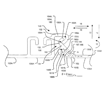
surface (e.g. a curved wall where outer surfaces 135A of panels 133A, 133B
form a
convex surface across connection 150), the value of 0õ,,,,õ be less than 180
(e.g. in a range
between 160 and 179 ). Conversely, in some cases where it is desired that
panels 133A,
133B join together to provide a concave surface (e.g. a curved wall where
outer surfaces
135A of panels 133A, 133B form a concave surface across connection 150), the
value of
61, be greater than 180 (e.g. in a range between 181 and 200 ).
18
CA 02855742 2014-05-13
WO 2013/075251
PCT/CA2012/050850
[0052] In some embodiments, it may be desirable to provide 0õ,õ with a value
that is less
than the desired ultimate angle Ode,,,ed between outer surfaces 135A of panels
133A,
133B. This may be accomplished, for example, by providing interior bevel angle
fl and/or
interior bevel angle a of the abutment surfaces at other angles such that the
sum of
interior bevel angle /3 and interior bevel angle a (i.e. 0) is less than the
desired ultimate
angle desired. Such an embodiment is shown in Figures 6A and 6B, which
respectively
depict enlarged partial plan views of a loose-fit connection 380 and a
completed
connection 350 between a pair of edge-adjacent panels 333A, 333B and their
respective
connector components 332, 334 according to another embodiment. Panels 333A,
333B
may be similar to the above-described panels 133A, 133B and similar reference
numbers
are used to refer to features of panels 333A, 333B and 133A, 133B except that
the
reference numbers of panels 333A, 333B are preceded by the numeral "3" whereas
the
reference numbers of panels 133A, 133B are preceded by the numeral "1".
[0053] Panels 333A. 333B differ from panels 133A, 133B only in that 61õ, which
is
provided by the sum of interior bevel angle and interior bevel angle a of
abutment
surfaces 372, 357, is less than the desired ultimate angle Ode,iõd. In the
case of the Figure
6A and 6B embodiment, the desired ultimate angle Odesired=180 . but this is
not necessary
and the desired ultimate angle desired may be greater than 180 (e.g. for
concave walls) or
less than 180 (e.g. for convex walls). In the particular case of the
embodiment of Figures
6A and 6B interior bevel angle )6 of abutment surface 372 is still
approximately 45 while
interior bevel angle a of abutment surface 357 has been reduced to
approximately 133 .
Accordingly, 0,õ,,,-1780. In some embodiments, ()max (the sum of bevel angles
a, fi) may
be designed to be in a range of 95-99.5% of the value of the desired ultimate
angle desired.
In still other embodiments, ()max may be in a range of 97-99.5% of the value
of the desired
ultimate angle ()desired. Since Onicir represents the sum of the bevel angles
a and fi, it will be
appreciated that selection of a value for max may be accomplished by varying
either or
both of bevel angles a and fl.
[0054] Obtaining the desired ultimate angle Odõired may involve forcing
abutment
surfaces 157, 172 into one another with such force that the force causes
deformation of
panels 333A. 333B (or more particularly, connector components 332, 334) so
that the
interior angle between panels 333A, 333B increases from aka to desired. Such
force may
19
CA 02855742 2014-05-13
WO 2013/075251
PCT/CA2012/050850
be applied when support members 136 are connected to panels 333A, 333B, for
example.
For example, when O. is less than 0 dcsiõd and support members 136 are
connected to
panels 333A. 333B, outwardly directed force may be applied to panels 333A.
333B, such
that one or both of panels 333A, 333B may tend to deform under the forces
caused this
pressure in the direction of arrow 15. This deformation may cause exterior
surfaces 335A
of panels 333A, 333B to become relatively more parallel with one another ¨
i.e. so that
the angle between the exterior surfaces 335A of panels 333A, 333B changes from
0,,a,
(prior to connection of support members 136) to a value closer to the desired
ultimate
angle desired (after the connection of support members 136). Accordingly,
selecting a
value of 0 0
max<- desired may effectively result in an angle between the exterior surfaces
335A of panels 333A, 333B that is closer to Odõired (after the connection of
support
members 136). In the case of the illustrated embodiment of Figures 6A and 6B,
selecting
a value of 0õ<180 (prior to the connection of support members 136) may
effectively
create an angle between the exterior surfaces 335A of panels 333A, 333B that
is closer to
Odesit ed=180 (after the connection of support members 136).
[0055] The forces which cause deformation of panels 333A, 333B so that the
interior
angle between panels 333A, 333B increases from On. to edoired may additionally
or
alternatively come from the introduction of liquid concrete to the
corresponding
formwork. For example, where panels 333A, 333B and their respective connection
350
.. (Figure 6B) are part of a formwork and liquid concrete (or other curable
construction
material) is introduced into an interior of the formwork, the weight of the
liquid concrete
applies pressure to panels 333A, 333B. More particularly, forces associated
with this
pressure will act generally perpendicularly to interior surfaces 335B of
panels 333A,
333B as shown by arrows 14 (in the case of panel 333A) and 15 (in the case of
panel
333B). One or both of the portions of panels 333A, 333B illustrated in Figures
6A and 6B
may tend to deform under the forces caused this pressure in the direction of
arrow 15.
This deformation under the weight of liquid concrete may cause exterior
surfaces 335A
of panels 333A, 333B to become relatively more parallel with one another ¨
i.e. so that
the angle between the exterior surfaces 335A of panels 333A, 333B changes from
0.
(prior to the introduction of concrete) to a value closer to the desired
ultimate angle
Odesired (after the introduction of concrete). Accordingly, selecting a value
of Off.< Ode,ired
CA 02855742 2014-05-13
WO 2013/075251
PCT/CA2012/050850
(prior to the introduction of concrete) may effectively result in an angle
between the
exterior surfaces 335A of panels 333A, 333B that is closer to desired (after
the
introduction of concrete). In the case of the illustrated embodiment of
Figures 6A and 6B,
selecting a value of O.,<180 (prior to the introduction of concrete) may
effectively
create an angle between the exterior surfaces 335A of panels 333A, 333B that
is closer to
Odesired=180 (after the introduction of concrete).
[0056] Providing a value of emax<edesired may also increase the sealing force
between
connector components 332, 334 of panels 333A, 333B. More particularly, forces
caused
by the connection of support members 136 to panels 333A, 333B and/or the
pressure
associated with the weight of liquid concrete may be directed generally
perpendicularly
to interior surface 335B of panel 333B. Forces oriented in this direction
include
transversely directed components which tend to pull the hooks 368 of connector
component 332 toward, and into more forceful engagement with, the hooks 359 of
connector component 334, thereby increasing the sealing force between
connector
components 332, 334 of panels 333A, 333B. Further forces oriented in this
direction
include outward components which create torques which tend to push abutment
surfaces
357, 372 toward, and into more forceful engagement with one another.
[0057] In other respects, panels 333A, 333B, their connector components 332,
334 and
their connections 380, 350 are substantially similar to panels 133A, 133B,
connector
components 132, 134 and connections 180, 150 described herein and any
reference to
panels 133A. 133B, connector components 132, 134 and connections 180, 150
should be
understood to be applicable (where appropriate) to panels 333A, 333B,
connector
components 332, 334 and connections 380, 350.
[0058] Referring back to Figures 4E and 4F, the surface area of contact
between
abutment surfaces 157, 172 when connector components 132, 134 form connection
150
may comprise a relatively large contact surface area. Such a large contact
surface area
may advantageously improve the seal provided by connection 150 against fluids
(e.g.
liquids or, in some cases, gases). Such a large contact surface area may also
improve the
robustness of connection 150 to thermal expansion ¨ e.g. because abutment
surfaces 157,
172 may be permitted to move relative to one another (as may occur with
thermal
expansion or corresponding contraction), while still maintaining connection
150 with a
21
CA 02855742 2014-05-13
WO 2013/075251
PCT/CA2012/050850
sufficient seal against the passage of fluids. In some embodiments, a ratio of
the contact
surface area of abutment surfaces 157, 172 to the area associated with back
wall 167 is
greater than 25%. In some embodiments, this ratio is greater than 33%. It will
be
appreciated that the cross-section of panels 133A, 133B may be uniform along
their
longitudinal dimensions (e.g. into and out of the page in the illustrated
views of Figure
4E and 4F). Consequently in such embodiments, these surface area ratios may be
equivalently expressed as ratios of the width of the abutment surfaces 157,
172 (in a
direction along their contact) to the depth of back wall 167 (or effectively
to the depth of
connector component 132).
[0059] In some embodiments, a sealing material (not shown) may be provided on
some
surfaces of connector components 132, 134. Such sealing material may be
relatively soft
(e.g. elastomeric) when compared to the material from which the remainder of
panels 133
are formed. Such sealing materials may be provided using a co-extrusion
process or
coated onto connector components 132, 134 after fabrication of panels 133, for
example.
Such sealing materials may help to make connections 150 between edge adjacent
panel
133A, 133B impermeable to liquids or gasses. Such sealing materials may be
provided on
any one or more contact surfaces of connector components 132, 134, including,
by way
of non-limiting example, such sealing materials may be provided on: one or
both of
fingers 156; one or both of restraining arms 164; one or both of phalanxes
161; elbow
169B; knee 153; and one or both of abutment surfaces 172, 157.
[0060] Figure 7A shows a connection 450 between connector components 432, 434
of
edge-adjacent panels 433A, 433B according to an example embodiment where
elastomeric sealing material 417 is provided on abutment surface 472 in a
vicinity of
knee 469B. Sealing material 417 may be co-extruded with panel 433A as
discussed
above. When abutment surfaces 457, 472 abut one another as described above to
provide
connection 450, sealing material 417 may be compressed to help maintain a seal
between
abutment surfaces 457, 472 that reduces the permeability of connection 450 to
fluids. In
other respects, panels 433A, 433B and connection 450 may be similar to panels
133A,
133B and connection 150 described herein.
[0061] Bevelled abutment surfaces 152, 157 of connector components 132, 134
are
generally planar surfaces. In some embodiments, the bevelled abutment surfaces
of
22
CA 02855742 2014-05-13
WO 2013/075251
PCT/CA2012/050850
connector components may be provided with one or more complementary profile
features
(e.g. one or more complementary convexities and concavities) which may help to
provide
connections between the corresponding connector components and corresponding
edge-
adjacent panels. Figure 7B shows a connection 550 between connector components
532,
534 of edge-adjacent panels 533A, 533B according to an example embodiment
where
abutment surface 572 comprises a concavity 517 and abutment surface 557
comprises a
complementary convexity 519 which projects into concavity 517 when forming
connection 550. The projection of convexity 519 into concavity 517 may help to
register
connector components 532, 534 and panels 533A. 533B relative to one another
during the
formation of connection 550 and may also help to prevent connection 550 from
unzipping. Sealing material (not shown) may be co-extruded or otherwise
applied to the
surface(s) of one or both of concavity 517 and convexity 519 to help seal
connection 550.
In other respects, panels 533A, 533B and connection 550 may be similar to
panels 133A,
133B and connection 150 described herein.
[0062] In some embodiments, multiple complementary profile features may be
provided
on the bevelled abutment surfaces of connector components. Figure 7C shows a
connection 550' between connector components 532', 534' of edge-adjacent
panels
533A', 533B' according to an example embodiment where abutment surface 572'
comprises a plurality of alternating concavities and convexities (e.g. in a
toothed pattern
517') and abutment surface 557 comprises a complementary plurality of
alternating
concavities and convexities (e.g. in a complementary toothed patter 519').
When forming
connection 550', toothed patterns 517', 519' engage one another and may help
to register
connector components 532', 534' and panels 533A', 533B' relative to one
another and
may also help to prevent connection 550' from unzipping. Sealing material (not
shown)
may be co-extruded or otherwise applied to the surface(s) of one or both of
toothed
patterns 517', 519' to help seal connection 550'. In other respects, panels
533A'. 533B'
and connection 550' may be similar to panels 133A, 133B and connection 150
described
herein.
[0063] Figure 7D shows a connection 550" between connector components 532".
534" of
edge-adjacent panels 533A", 533B" according to an example embodiment where
abutment surface 572" comprises a plurality of alternating concavities and
convexities
23
CA 02855742 2014-05-13
WO 2013/075251
PCT/CA2012/050850
(e.g. in a toothed pattern 517") and abutment surface 557 is coated with a
layer of sealing
material 521 (e.g. elastomeric material). Sealing material 521 may be co-
extruded with
panel 533B" as discussed above. When forming connection 550", toothed pattern
517"
may be squeezed into sealing material 521 may help to form a seal between
abutment
surfaces 557", 572" that reduces the permeability of connection 550" to
fluids. In other
respects, panels 533A", 533B" and connection 550" may be similar to panels
133A, 133B
and connection 150 described herein.
[0064] Figure 8A is a partial cross-sectional view of a portion of a modular
stay-in-place
formwork 628 according to an example embodiment. Formwork 628 is similar to
formwork 128 discussed above and comprises panels 133, 130 and support members
136
which are substantially similar to panels 133, 130 and support members 136 of
formwork
128. Formwork 628 differs from formwork 128 in that formwork 628 comprises
tensioning braces 640 which extend between panels 133 and support members 136
to
reinforce connections 150. Tensioning braces 640, which may be apertured to
permit
concrete flow therethrough, comprise connector components 642 at their
respective ends
to connection to complementary connector components 644, 646 on panels 133 and
support members 136 respectively. In the illustrated embodiment, connector
components
642 of tensioning braces 640 comprise female, C-shaped connector components
which
slidably receive male, T-shaped connector components 644, 646 of panels 133
and
support members 136.
[0065] In other embodiments, connector components 642, 644, 646 may be
different than
those shown in the illustrated embodiment and may connect to one using
techniques other
than relative sliding, such as, by way of non-limiting example, deformable -
snap-
together" connections, pivotal connections, push on connections and/or the
like. In some
embodiments, tensioning braces 640 may be provided with male connector
component
and panels 133 and support members 136 may comprise female connector
components.
While not shown in the illustrated embodiment, tensioning braces 640 may
additionally
or alternatively be connected between connector components 648 of support
members
136 and connector components 650 of panels 130.
[0066] In other respects, formwork 628 is substantially similar to formwork
128
described herein.
24
CA 02855742 2014-05-13
WO 2013/075251
PCT/CA2012/050850
[0067] Figure 8B is a partial cross-sectional view of a portion of a modular
stay-in-place
formwork 628' according to an example embodiment. Formwork 628' is similar to
formwork 128 discussed above and comprises panels 133 and support members 136
which are substantially similar to panels 133 and support members 136 of
formwork 128.
Formwork 628' differs from formwork 128 in that formwork 628' comprises wall
segments 627', 629' which are both provided by panels 133 ¨ i.e. formwork 628'
comprises panels 133 on both sides of each support member 136. The connections
150
between, and operation of, panels 133 on ether side of support members 136 are
substantially similar to that described above. In other respects, formwork
628' is
substantially similar to formwork 128 described herein.
[0068] Figure 9A is a partial cross-sectional view of a portion of a modular
stay-in-place
formwork 728 according to an example embodiment. Formwork 728 is similar to
formwork 128 discussed above and similar reference numbers are used to refer
to similar
features, except that features of formwork 728 are referred to using reference
numbers
preceded by the numeral "7" whereas features of formwork 128 are referred to
using
reference numbers preceded by the numeral "1". Formwork 728 of the illustrated
embodiment includes panels 730, 733 and support members 736 which are
connected to
one another to provide wall segments 727, 729 which, in the illustrated
embodiment,
extend in the vertical direction (into and out of the page in the Figure 9A
view) and in the
transverse direction 17.
[0069] Panels 730, 733 of formwork 728 comprise female connector components
732
and male connector components 734 which are respectively substantially similar
to
female connector components 132 and male connector components 134 described
herein.
More particularly, female and male connector components 732, 734 comprise
engagement portions and abutment portions (not specifically enumerated in
Figure 9A)
which are substantially similar to engagement portions 182, 186 and abutment
portions
184, 188 of connector components 132, 134 described herein and which function
in a
similar manner to provide connections 750 between edge-adjacent panels.
[0070] Panels 730, 733 differ from panels 130, 133 in that panels 730
respectively
comprise outward facing (exterior) surfaces 731A, 735A and inward facing
(interior)
surfaces 731B, 735B that are spaced apart from one another and inward facing
(interior)
CA 02855742 2014-05-13
WO 2013/075251
PCT/CA2012/050850
surfaces 731B. 735B of panels 730, 733 are shaped to provide inwardly
protruding
convexities 703 between the transverse edges of panels 730, 733. In the
illustrated
embodiment. convexities 703 are arcuately shaped, but this is not necessary
and
convexities 703 may be linearly convex.
[0071] Extending between exterior surfaces 731A, 735A and interior surfaces
731B,
735B of panels 730, 733 comprise a plurality of brace elements 832A, 832B,
834A,
834B, 836A, 836B, 838A, 838B, 840A, 840B. Brace elements 832A, 832B, 834A,
834B,
836A, 836B, 838A, 838B, 840A, 840B of the illustrated embodiment are oriented
at non-
orthogonal angles to both exterior surfaces 731A, 735A and interior surfaces
731B, 735B
of panels 730, 733. In the illustrated embodiment, all of brace elements 832A,
832B,
834A, 834B, 836A, 836B, 838A, 838B, 840A, 840B in any one panel 730, 733 are
non-
parallel with one another. In the illustrated embodiment, brace elements 832A,
832B,
834A, 834B, 836A, 836B, 838A, 838B, 840A, 840B are oriented to be symmetrical
about
a notional transverse mid-plane 842 - i.e. more particularly:
= the transversely outermost pair of brace elements 832A, 832B have
orientations
that are mirror images of one another relative to mid-plane 842 and are
oriented
with the same interior angle relative to exterior surfaces 731A, 735A;
= the second transversely outermost pair of brace elements 834A, 834B have
orientations that are mirror images of one another relative to mid-plane 842
and
are oriented with the same interior angle relative to exterior surfaces 731A,
735A;
= the third transversely outermost pair of brace elements 836A, 836B have
orientations that are mirror images of one another relative to mid-plane 842
and
are oriented with the same interior angle relative to exterior surfaces 731A,
735A;
= the fourth transversely outermost pair of brace elements 838A, 838B have
orientations that are mirror images of one another relative to mid-plane 842
and
are oriented with the same interior angle relative to exterior surfaces 731A,
735A;
= the transversely innermost pair of brace elements 840A, 840B have
orientations
that are mirror images of one another relative to mid-plane 842 and are
oriented
with the same interior angle relative to exterior surfaces 731A, 735A.
[0072] This shape of exterior and interior surfaces 731A, 731B and 735A, 735B
and the
orientations of brace elements 832A, 832B, 834A, 834B, 836A, 836B, 838A, 838B,
26
CA 02855742 2014-05-13
WO 2013/075251
PCT/CA2012/050850
840A, 840B can reduce deformation (e.g. pillowing and bellying) in panels 730,
733. It
will be appreciated that panels 730. 733 of the illustrated embodiment
comprise five pairs
of brace elements 832A, 832B, 834A, 834B, 836A, 836B, 838A, 838B, 840A, 840B
that
are symmetrical with respect to notional mid-plane 842, but that in other
embodiments,
panels may comprise other numbers of pairs of symmetrical brace elements.
[0073] Formwork 728 also differs from formwork 128 in that support members 736
comprise T-shaped male connector components 739 and panels 730, 733 comprise
complementary female C-shaped connector components 742 which have different
shapes
(but similar functionality) to connector components 139, 142 of support
members 136
and panels 130, 133.
[0074] Panels 730, 733 also differ from panels 130, 133 in that panels 730,
733 comprise
connector component reinforcement structures 721 which reinforce connector
components 732 and 742 and provide panels 730, 733 with additional stiffness
and
resistance to deformation in the region of connector components 732 and 742.
In the
illustrated embodiment, connector component reinforcement structures 721 are
rectangular shaped comprising inward/outward members and transverse members
(not
specifically enumerated), although this is not necessary. In other
embodiments, connector
component reinforcement structures 721 could be provided with other shapes,
while
performing the same or similar function. For example, connector component
reinforcement structures 721 could be made to have one or more non-orthogonal
and
non-parallel brace elements (e.g. similar to brace elements 832A, 832B, 834A,
834B,
836A, 836B, 838A, 838B, 840A, 840B described above) or connector component
reinforcement structures 721 could be made to have one or more orthogonal and
parallel
brace elements.
[0075] In other respects, formwork 728 is substantially similar to formwork
128
described herein.
[0076] Figure 9B is a partial cross-sectional view of a portion of a modular
stay-in-place
formwork 728' according to an example embodiment. Formwork 728' is similar in
many
respects to formwork 728 discussed above and similar reference numbers are
used to
refer to similar features, except that features of formwork 728' are referred
to using
reference numbers followed by the prime symbol ('). Panels 733' of formwork
728'
27
CA 02855742 2014-05-13
WO 2013/075251
PCT/CA2012/050850
comprise female connector components 732' and male connector components 734'
which
are respectively substantially similar to female connector components 732 and
male
connector components 734 of panels 733 described herein. Panels 733' are also
similar to
panels 733 in that they comprise outward facing (exterior) surfaces 735A' and
inward
facing (interior) surfaces 735B' that are spaced apart from one another and
interior
surfaces 735B' of panels 733' are shaped to provide inwardly protruding
convexities 703'
between the transverse edges of panels 733'. Panels 733' are also similar to
panels 733 in
that they comprise brace elements (not specifically enumerated in Figure 9B)
which
extend between exterior surfaces 735A' and interior surfaces 735B' of panels
733' and
which are substantially similar to brace elements 832A, 832B, 834A, 834B,
836A, 836B,
838A, 838B, 840A, 840B of panels 733 described herein.
[0077] Formwork 728' differs from formwork 728 in that formwork 728' comprises
support members 136 (substantially identical to those of formwork 128) and
edge-
adjacent pairs of panels 733' are each provided with a J-shaped connector
component
742A', 742B' at their transverse edges for engaging a portion of the connector
component 139 of support member 136. More particularly, when panels 733' are
connected in edge-adjacent relationship, a pair of J-shaped connector
components 742A'
742B' (one from each edge-adjacent panel 733') together provide a "double-J"
shaped
female connector component for receiving the complementary connector component
139
of support member 136. This configuration of connector components may help to
reinforce the connections between edge-adjacent panels 733'.
[0078] In other respects, formwork 728 is substantially similar to formwork
128
described herein.
[0079] Processes, methods, lists and the like are presented in a given order.
Alternative
examples may be performed in a different order, and some elements may be
deleted,
moved, added, subdivided, combined, and/or modified to provide additional,
alternative
or sub-combinations. Each of these elements may be implemented in a variety of
different ways. Also, while elements are at times shown as being performed in
series,
they may instead be performed in parallel, or may be performed at different
times. Some
elements may be of a conditional nature, which is not shown for simplicity
28
CA 02855742 2014-05-13
WO 2013/075251
PCT/CA2012/050850
[0080] Where a component (e.g. a connector component, etc.) is referred to
above, unless
otherwise indicated, reference to that component (including a reference to a
"means")
should be interpreted as including as equivalents of that component any
component
which performs the function of the described component (i.e. that is
functionally
equivalent), including components which are not structurally equivalent to the
disclosed
structure which performs the function in the illustrated exemplary embodiments
of the
invention.
[0081] Those skilled in the art will appreciate that directional conventions
such as
"vertical", "transverse", "horizontal", "upward", "downward", -forward",
"backward",
"inward". "outward", "vertical", "transverse" and the like, used in this
description and
any accompanying claims (where present) depend on the specific orientation of
the
apparatus described. Accordingly, these directional terms are not strictly
defined and
should not be interpreted narrowly.
[0082] Unless the context clearly requires otherwise, throughout the
description and any
claims (where present), the words "comprise," "comprising," and the like are
to be
construed in an inclusive sense, that is, in the sense of "including, but not
limited to." As
used herein, the terms "connected," "coupled," or any variant thereof, means
any
connection or coupling, either direct or indirect, between two or more
elements: the
coupling or connection between the elements can be physical, logical, or a
combination
thereof. Additionally, the words "herein," "above," "below," and words of
similar import,
shall refer to this document as a whole and not to any particular portions.
Where the
context permits, words using the singular or plural number may also include
the plural or
singular number respectively. The word "or," in reference to a list of two or
more items,
covers all of the following interpretations of the word: any of the items in
the list, all of
the items in the list, and any combination of the items in the list.
[0083] While a number of exemplary aspects and embodiments have been discussed
above, those of skill in the art will recognize certain modifications,
permutations,
additions and sub-combinations thereof. For example:
= In the Figure 3 embodiment, formwork 128 comprises a pair of wall
segments
127, 129 which extend in the vertical direction 19 and the transverse
direction 17.
Formworks used for tilt-up walls and/or for lining structures need only
comprise a
29
CA 02855742 2014-05-13
WO 2013/075251
PCT/CA2012/050850
single wall segment. In addition, structures fabricated using formworks
according
to various embodiments of the invention are not limited to walls. In such
embodiments, groups of edge-adjacent panels 133 connected in edge-to-edge
relationship at connections 150 may be more generally referred to as formwork
segments instead of wall segments. In the illustrated embodiment, wall
segments
127, 129 are spaced apart from one another in the inward-outward direction by
an
amount that is relatively constant, such that wall segments 127, 129 are
generally
parallel. This is not necessary. In some embodiments, wall segments 127, 129
need not be parallel to one another and different portions of formworks
according
to the invention may have different inward-outward dimensions.
= In some embodiments, it may be desirable to provide walls which
incorporate
insulation. Insulation may be provided in the form of rigid foam insulation.
Non-
limiting examples of suitable materials for rigid foam insulation include:
expanded poly-styrene, poly-urethane, poly-isocyanurate or any other suitable
moisture resistant material. By way of non-limiting example, insulation layers
may be provided in any of the forms described herein. Such insulation layers
may
extend in the longitudinal direction and in a transverse direction (i.e.
between the
interior and exterior surfaces of a formwork). Such insulation layers may be
located centrally within the wall or at one side of the wall. Such insulation
may be
provided in segments whose transverse widths match those of the panels (e.g.
panels 133) described herein and may fit between corresponding pairs of
support
members (e.g. support members 136) described herein. In some embodiments,
sound-proofing materials may be layered into the forms described herein in a
manner similar to that of insulation.
= As is well known in the art, reinforcement bars (sometimes referred to as
rebar)
may be used to strengthen concrete structures. Rebar may be assembled into the
formworks described above. By way of non-limiting example, rebar may be
assembled into formwork 128 described above by extending rebar transversely
(e.g. horizontally) through apertures 141, 143 in support members 136 (Figure
3D) and vertically oriented rebar may be tied or otherwise fastened to the
horizontal rebar.
CA 02855742 2014-05-13
WO 2013/075251
PCT/CA2012/050850
= In the embodiments described herein, the structural material used to
fabricate the
wall segments is concrete. This is not necessary. In some applications, it may
be
desirable to use other structural materials which may be initially be
introduced
placed into formworks and may subsequently solidify or cure.
= In the embodiments described herein, the outward facing surfaces (e.g.
surfaces
135A) of some panels (e.g. panels 133) are substantially flat. In other
embodiments, panels may be provided with inward/outward corrugations. Such
corrugations may extend longitudinally and/or transversely. Such corrugations
may help to further prevent or minimize pillowing of panels under the weight
of
liquid concrete.
= In the embodiments described herein, various features of the panels
described
herein (e.g. connector components 132, 134 of panels 133) are substantially co-
extensive with the panels in longitudinal dimension 19. This is not necessary.
In
some embodiments, such features may be located at various locations on the
longitudinal dimension 19 of the panels and may be absent at other locations
on
the longitudinal dimension 19 of the panels.
= In some embodiments. the formworks described herein may be used to
fabricate
walls, ceilings or floors of buildings or similar structures. In general, the
formworks described above are not limited to building structures and may be
used
to construct any suitable structures formed from concrete or similar
materials.
Non-limiting examples of such structures include transportation structures
(e.g.
bridge supports and freeway supports), beams, foundations, sidewalks, pipes,
tanks, beams and the like.
= Structures (e.g. walls) fabricated according to the invention may have
curvature.
Where it is desired to provide a structure with a certain radius of curvature,
panels
on the inside of the curve may be provided with a shorter length than
corresponding panels on the outside of the curve. This length difference will
accommodate for the differences in the radii of curvature between the inside
and
outside of the curve. It will be appreciated that this length difference will
depend
on the thickness of the structure.
31
CA 02855742 2014-05-13
WO 2013/075251
PCT/CA2012/050850
= Portions of connector components may be coated with or may otherwise
incorporate antibacterial, antiviral and/or antifungal agents. By way of non-
limiting example. MicrobanTM manufactured by Microban International, Ltd. of
New York, New York may be coated onto and/or incorporated into connector
components during manufacture thereof. Portions of connector component may
also be coated with elastomeric sealing materials. Such sealing materials may
be
co-extruded with their conesponding components.
= Many embodiments and variations are described above. Those skilled in the
art
will appreciate that various aspects of any of the above-described embodiments
may be incorporated into any of the other ones of the above-described
embodiments by suitable modification.
32