Note: Descriptions are shown in the official language in which they were submitted.
CA 02855946 2014-05-14
WO 2013/074767 PCT/US2012/065246
FREEZE PROTECTION SYSTEM FOR SOLAR RECEIVER
[0001] This application claims priority to U.S. Provisional Patent
Application
Serial No. 61/560,538, filed on November 16, 2011. The disclosure of this
application is hereby fully incorporated by reference in its entirety.
BACKGROUND
[0002] The present disclosure relates, in general, to the field of solar
power
generation. More particularly, the present disclosure is directed to the
protection or
inhibition of freezing or solidification of a heat transfer fluid in a solar
receiver.
[0003] A solar receiver is a primary component of a solar energy
generation
system whereby sunlight is used as a heat source for the eventual production
of
superheated high quality steam that is used to turn a turbine generator, and
ultimately produce electricity using the Rankine cycle or provide steam for
other
thermal processes.
[0004] Generally, the solar receiver is positioned on top of an elevated
support
tower which rises above a ground level or grade. The solar receiver is
strategically
positioned in an array of reflective surfaces, such as a field of heliostats
(or mirrors),
that collect rays of sunlight and redirect or reflect those rays to the heat
absorbing
surfaces of the solar receiver. This solar energy is then absorbed by the
working
heat transfer fluid (HTF) flowing through the solar receiver. The reflective
surfaces
may be oriented in different positions through the day to track the sun and
maximize
reflected sunlight to the heat absorbing surfaces.
[0005] The solar receiver is an assembly of tubes with water, steam,
molten
salts, or other heat transfer fluid (HTF) flowing inside the tubes. The HTF
inside the
tubes of the receiver absorbs the concentrated solar energy, causing the HTF
to
increase in temperature and/or change phases, so that the HTF captures the
solar
energy. The heated HTF is then either directly routed to a turbine generator
to
generate electrical power or is indirectly routed to a storage tank for later
use.
[0006] A common problem in solar receivers relates to temperature drops
that
occur during periods of solar inactivity, e.g., dense/continuous cloud cover,
nightfall,
and the like. During periods where solar activity, e.g., heat, is noticeably
absent, the
temperature of the heat transfer fluid may drop to temperatures that approach
or fall
below freezing/solidification. Such periods can occur in varying climates,
including
-1-
CA 02855946 2014-05-14
WO 2013/074767 PCT/US2012/065246
desert environments, where concentrated solar power (CSP) plants are primarily
located. When using water as a heat transfer fluid, freezing of the fluid
within the
receiver may occur as external temperatures drop (e.g. winter) and offsetting
heat
from the sun is unavailable. The evaporator tube panels, which are filled with
water,
are exposed to ambient conditions and are particularly in danger of freezing.
If the
receiver is not drained, the heat transfer fluid will expand and could rupture
the
tube(s).
[0007] Current preventive measures include draining the heat transfer
fluid
from the solar receiver so as to prevent damage to components of the solar
receiver
caused by freezing. These measures are not practical for commercial plants.
There
are also other disadvantages, including wasting the drained heat transfer
fluid and
chemicals, consumption of nitrogen (to displace air for corrosion control)
which
increases operating costs, the time needed to refill the solar receiver and
the
resulting increase in startup time (and decreased availability), and the
discarding of
thermal energy in the heat transfer fluid contained in the steam drum or
vertical
separator (discussed later). In addition, the receiver is at risk for scaling
and
corrosion during the time period required to get the water quality back to the
proper
chemistry. For these reasons, it would be advantageous to leave the solar
receiver
full of HTF.
[0008] Electrical trace heating is a system used to maintain or raise the
temperature of some instrument tubing and small bore piping. Generally, an
electrical heating element is run in thermal contact along the length of a
pipe, and
the pipe is then covered with thermal insulation to retain heat losses from
the pipe.
However, it is not practical or cost-effective to heat trace all of the water-
filled solar
receiver panel tubes due to their large quantity and small size. For example,
there
could be several hundred evaporator tubes in a solar receiver. Additionally,
there is
also a need for a control system for monitoring and activating a
freeze/solidification
protection system to reduce or prevent damage and enhance the efficiency of a
solar
receiver.
-2-
CA 02855946 2014-05-14
WO 2013/074767 PCT/US2012/065246
BRIEF DESCRIPTION
[0009] The present disclosure provides a freeze protection system for a
solar
receiver. The receiver is equipped with at least one alternate heat source
that is
capable of generating movement and temperature increases in the heat transfer
fluid
inside the solar receiver so as to prevent the freezing of the fluid. A
controller is
included to control the alternate heat source.
[0010] Disclosed in various embodiments herein is a steam/water solar
receiver, comprising at least one tube panel, a steam separation device, a
downcomer, and at least one alternate heat source. The at least one tube panel
comprises a plurality of vertical tubes for conveying a heat transfer fluid.
The tubes
are interconnected by at least one upper header and at least one lower header.
The
steam separation device is fluidly connected to the at least one upper header
of the
at least one evaporator tube panel. The downcomer is fluidly coupled to the
steam
separation device and the at least one lower header of the at least one
evaporator
tube panel. The at least one alternate heat source is selectively operative on
a heat
transfer fluid within the solar receiver.
[0011] The at least one alternate heat source may be configured to heat
the
heat transfer fluid so as to induce a natural circulation flow through the
solar
receiver.
[0012] The at least one alternate heat source can be positioned so as to
contact an outside portion of the at least one lower header or can be
positioned
within the at least one lower header. Alternatively, the at least one
alternate heat
source can be positioned so as to contact an outside portion of the downcomer
or
can be positioned within the downcomer. The at least one alternate heat source
may be an electric band heater or a steam sparger.
[0013] The solar receiver may further comprise at least one temperature
sensor for sensing a temperature of the heat transfer fluid; or may
alternatively
further comprise a controller configured to control the at least one alternate
heat
source.
[0014] The controller can be configured to receive the sensed temperature
of
the heat transfer fluid and selectively operate the at least one alternate
heat source
in response thereto. Alternatively, the controller can be configured to
compare the
sensed temperature to a preselected threshold temperature, such that the at
least
-3-
CA 02855946 2014-05-14
WO 2013/074767 PCT/US2012/065246
one alternate heat source is activated upon the sensed temperature meeting the
preselected threshold temperature.
[0015] Sometimes, the at least one alternate heat source can be
positioned to
contact an outside portion of at least one of the tubes. Other times, the at
least one
alternate heat source can be positioned so as to contact an outside portion of
a
supply pipe fluidly connecting the lower header with the downcomer, or can be
positioned within the supply pipe.
[0016] The steam separation device may be a steam drum or a vertical
separator. The at least one alternate heat source can be positioned so as to
contact
an outside portion of a base of the vertical separator, or can be positioned
within the
base of the vertical separator.
[0017] The solar receiver may further comprise an isolation valve above a
level at which the steam separation device is fluidly connected to the upper
header.
The isolation valve can be located in the saturated connection piping between
the
steam separation device and the tube panel(s).
[0018] Also disclosed in various embodiments is a solar receiver
comprising:
at least one tube panel comprising a plurality of vertical tubes for conveying
a heat
transfer fluid, wherein the tubes are interconnected by at least one upper
header and
at least one lower header; a vertical separator; a downcomer in fluid
communication
with the vertical separator; at least one riser fluidly connecting the at
least one upper
header and the vertical separator; at least one supply pipe fluidly connecting
the at
least one lower header and the downcomer; and at least one alternate heat
source in
contact with the downcomer, the at least one lower header, or the at least one
tube
panel, the at least one alternate heat source configured to heat the
associated heat
transfer fluid contained in the solar receiver.
[0019] The solar receiver may further comprise at least one temperature
sensor in contact with the heat transfer fluid, ambient air surrounding the
solar
receiver, the vertical separator, the downcomer, the at least one tube panel,
the at
least one riser, or the at least one supply pipe.
[0020] The solar receiver may further comprise a controller including one
or
more processors in communication with the at least one temperature sensor and
the
alternate heat source. The controller can be configured to receive temperature
information from the at least one temperature sensor, and operate the at least
one
alternate heat source in response to received temperature information. The
-4-
CA 02855946 2014-05-14
WO 2013/074767 PCT/US2012/065246
controller can be further configured to compare received temperature
information to
at least one preselected threshold temperature, and wherein the at least one
alternate heat source is activated in response to an output of such
comparison.
[0021] The at least one alternate heat source may be a variable heat
source
or a constant heat source. Sometimes, the at least one alternate heat source
is
configured to apply a selected amount of thermal energy to the associated heat
transfer fluid so as to induce circulation of the heat transfer fluid in the
solar receiver.
Other times, the at least one alternate heat source is in contact with the
downcomer
such that the induced circulation is a natural circulation of the associated
heat
transfer fluid.
[0022] In some embodiments, the solar receiver further comprises a
circulation pump fluidly coupled to the downcomer, the at least one lower
header, or
the at least one upper header.
[0023] Also disclosed in various embodiments herein is a solar energy
generation system, comprising: a solar receiver comprising a plurality of
fluid-filled
components; and at least one alternate heat source in contact with at least a
portion
of at least one of the fluid-filled components of the solar receiver.
[0024] The solar energy generation system may further comprise a
controller
in communication with the at least one alternate heat source, the controller
configured to control operations of the alternate heat source.
[0025] The solar energy generation system may further comprise at least
one
fluid temperature sensor in data communication with the controller, the at
least one
heat transfer fluid temperature sensor configured to detect a temperature of
an
associated heat transfer fluid within the solar receiver.
[0026] The solar energy generation system may further comprise at least
one
ambient air temperature sensor in data communication with the controller, the
at
least one ambient air temperature sensor configured to detect a temperature of
ambient air surrounding the solar energy generation system.
[0027] The solar energy generation system may further comprise at least
one
component temperature sensor in data communication with the controller, the at
least one component temperature sensor configured to detect a temperature of
at
least one component of the solar receiver.
[0028] The controller can be configured to receive fluid temperature
information from the at least one fluid temperature sensor, ambient air
temperature
-5-
CA 02855946 2014-05-14
WO 2013/074767 PCT/US2012/065246
information from the at least one ambient air temperature sensor, and
component
temperature information from the at least one component temperature sensor.
The
controller may be further configured to compare at least one of the received
temperature information to a preselected threshold temperature, and wherein
the
controller activates the at least one alternate heat source in accordance with
a result
of the comparison.
[0029] The plurality of fluid-filled components may include a vertical
separator,
at least one riser, at least one evaporator tube panel, at least one supply,
and a
downcomer. The solar energy generation system may further comprise a
circulation
pump configured to circulate the associated heat transfer fluid in the solar
energy
generation system. The controller can be operative to activate the circulation
pump
in accordance with a result of the threshold temperature comparison. The solar
receiver may include an isolation valve above a water level of the vertical
separator.
[0030] These and other non-limiting aspects and/or objects of the
disclosure
are more particularly described below.
BRIEF DESCRIPTION OF THE DRAWINGS
[0031] The following is a brief description of the drawings, which are
presented for the purposes of illustrating the exemplary embodiments disclosed
herein and not for the purposes of limiting the same.
[0032] FIG. 1 is an exploded perspective isometric view of an exemplary
embodiment of a solar receiver, illustrating the arrangement of heat transfer
surfaces, a vertical steam/water separator structurally and fluidly
interconnected
thereto; and a vertical support structure provided to top support the vertical
separator
and the heat transfer surfaces.
[0033] FIG. 2A is a side cross-sectional view of a tube panel with a
light
barrier and insulation.
[0034] FIG. 2B is a perspective view of the panel of FIG. 2A.
[0035] FIG. 3 is a view of the vertical steam/water separator,
illustrating
various connections thereto.
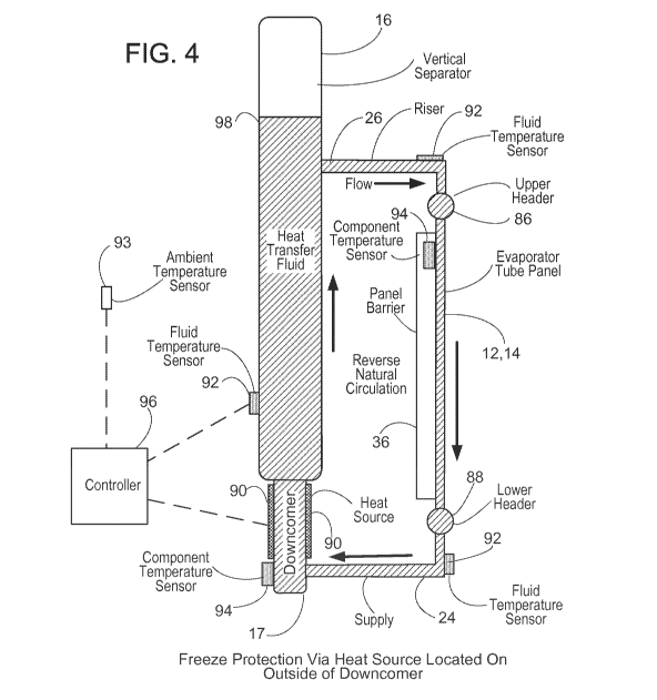
[0036] FIG. 4 and FIG. 5 are side views of a solar receiver using an
alternate
heat source for freeze protection on the outside of or within the downcomer.
-6-
CA 02855946 2014-05-14
WO 2013/074767 PCT/US2012/065246
[0037] FIG. 6 and FIG. 7 are side views of the solar receiver using an
alternate heat source for freeze protection on the outside of or within the
vertical
separator.
[0038] FIG. 8 and FIG. 9 are side views of the solar receiver using an
alternate heat source for freeze protection on the outside of or within the
lower
header.
[0039] FIG. 10 and FIG. 11 are side views of the solar receiver using an
alternate heat source for freeze protection on the outside of or within the
supply pipe.
[0040] FIG. 12 is a side view of the solar receiver using an alternate
heat
source for freeze protection in contact with the tube panel.
[0041] FIG. 13 diagramatically illustrates controller operation of freeze
protection equipment in the various embodiments described above.
DETAILED DESCRIPTION
[0042] A more complete understanding of the processes and apparatuses
disclosed herein can be obtained by reference to the accompanying drawings.
These figures are merely schematic representations based on convenience and
the
ease of demonstrating the existing art and/or the present development, and
are,
therefore, not intended to indicate relative size and dimensions of the
assemblies or
components thereof.
[0043] Although specific terms are used in the following description for
the
sake of clarity, these terms are intended to refer only to the particular
structure of the
embodiments selected for illustration in the drawings, and are not intended to
define
or limit the scope of the disclosure. In the drawings and the following
description
below, it is to be understood that like numeric designations refer to
components of
like function.
[0044] The modifier "about" used in connection with a quantity is
inclusive of
the stated value and has the meaning dictated by the context (for example, it
includes at least the degree of error associated with the measurement of the
particular quantity). When used with a specific value, it should also be
considered as
disclosing that value. For example, the term "about 2" also discloses the
value "2"
and the range "from about 2 to about 4" also discloses the range "from 2 to
4."
[0045] It should be noted that many of the terms used herein are relative
terms. For example, the terms "interior", "exterior", "inward", and "outward"
are
-7-
CA 02855946 2014-05-14
WO 2013/074767 PCT/US2012/065246
relative to a center, and should not be construed as requiring a particular
orientation
or location of the structure. Similarly, the terms "upper" and "lower" are
relative to
each other in location, i.e. an upper component is located at a higher
elevation than
a lower component.
[0046] The terms "horizontal" and "vertical" are used to indicate
direction
relative to an absolute reference, i.e. ground level. However, these terms
should not
be construed to require structures to be absolutely parallel or absolutely
perpendicular to each other. For example, a first vertical structure and a
second
vertical structure are not necessarily parallel to each other.
[0047] The solar receiver described in various embodiments herein
employs,
for exemplary purposes, a vertical steam/water separating device according to
the
teachings of U.S. Patent No. 6,336,429 to Wiener to separate the steam from
the
steam-water mixture produced by the solar receiver of the present disclosure.
The
entirety of U.S. Patent No. 6,336,429 to Wiener is hereby fully incorporated
by
reference herein. The vertical steam/water separator is structurally and
fluidly
interconnected with the heating surfaces of the solar receiver.
[0048] To the extent that explanations of certain terminology or
principles of
the heat exchanger, boiler and/or steam generator arts may be necessary to
understand the present disclosure, the reader is referred to Steam/ its
generation
and use, 40th Edition, Stultz and Kitto, Eds., Copyright 1992, The Babcock &
Wilcox Company, and to Steam/ its generation and use, 41st Edition, Kitto and
Stultz, Eds., Copyright 2005, The Babcock & Wilcox Company, the texts of
which
are hereby fully incorporated by reference herein.
[0049] The receiver is an assembly of tubes with molten salts or other
heat
transfer fluid (HTF) flowing inside the tubes. At grade, a field of mirrors
called
heliostats track the sun's movement and focus sunlight onto the heat transfer
surfaces of the receiver. The HTF inside the tubes of the receiver absorbs the
concentrated solar energy, causing the HTF to increase in temperature and/or
change phases, so that the HTF captures the solar energy.
[0050] The solar receiver of the present disclosure is advantageously
comprised of an arrangement of heat transfer surfaces and fluid conveying
conduits
(pipes, valves, etc.) and associated controls arranged in a particular fashion
to
transfer a desired amount of heat energy into the heat transfer fluid. The
heat
transfer surfaces are advantageously made of tubes arranged into tangent tube
-8-
CA 02855946 2014-05-14
WO 2013/074767 PCT/US2012/065246
panels, and are provided with inlet and outlet headers as required. As is
known to
those skilled in the art, the sizes of tubes, their material, diameter, wall
thickness,
number and arrangement for the heat transfer surfaces are based upon
temperature
and pressure for service, according to applicable design codes. Required heat
transfer characteristics, circulation ratios, spot absorption rates, mass flow
rates of
the working fluid within the tubes, etc. are also important parameters which
must be
considered. Depending upon the geographic location where the solar receiver is
to
be installed, applicable seismic loads and design codes are also considered.
[0051] Referring to FIGS. 1-3, there is shown a solar receiver 10
according to
present disclosure, and which is comprised of the following major components:
[0052] Evaporator or boiler tube panels 12;
[0053] Primary superheater (PSH) and secondary superheater (SSH) tube
panels 14;
[0054] A vertical steam/water separator 16;
[0055] A downcomer 17;
[0056] Vertical, internal support structure 18, buckstays 20, and tower
connection 22;
[0057] Supply pipes 24, risers 26 and saturated connection piping 28;
[0058] Spray water attemperator 30 and piping 32;
[0059] Header heat shields 34;
[0060] Light barrier 36 and insulation 38;
[0061] Instrumentation 40;
[0062] Platforms 42 and access ladders; and
[0063] Upper headers 86 and Lower headers 88.
[0064] The present disclosure relates to improved methods of freeze
protection for solar receivers 10, particularly when the solar receiver 10 is
a
steam/water receiver. Unlike current freeze protection methods involving
the
draining of the heat transfer fluid 98, the present disclosure achieves heat
transfer
fluid 98 movement in the solar receiver 10 by means of at least one
strategically
placed alternate heat source(s) 90 that is attached to the outside of fluid
bearing
components or within such components.
[0065] The alternate heat source more specifically is an artificial heat
source.
The term "artificial" refers to the ability to control whether heat is applied
or
generated by the alternate heat source at a desired time period. For example,
-9-
CA 02855946 2014-05-14
WO 2013/074767 PCT/US2012/065246
sunlight should not be considered an alternate heat source because it cannot
be
applied during the nighttime.
[0066] The alternate heat source 90 is advantageously controlled, via the
controller 96, to activate once the components cool to a set temperature that
is close
to, but above, the freezing point of the heat transfer fluid. Dependent upon
ambient
conditions, more or less energy may be required in order to maintain fluid
temperatures above freezing, so the energy output by the alternate heat source
90
may be variable and controlled in order to hold metal and fluid temperatures
correspondingly above the freezing temperature of the heat transfer fluid.
Suitable
examples of such alternate heat sources 90 include, for example and without
limitation, electric heaters (electric band heaters), steam heat (spargers),
gas-fired
heat, or any suitable combination thereof. Thus, as will be seen in FIGS. 4-
12, such
solar receivers also include the following major components:
[0067] Heat sources 90;
[0068] Internal Heat transfer fluid temperature sensors 92;
[0069] External Component temperature sensors 94; and
[0070] Controller 96.
[0071] Discussion is now made of the general configuration of the solar
receiver 10. Referring to FIGS. 1-3, the solar receiver 10 has an arrangement
of
evaporative 12 and superheater 14 heat transfer surfaces, a vertical
steam/water
separator 16 structurally and fluidly interconnected thereto; and a vertical,
internal
support structure 18 provided to top support the vertical steam/water
separator 16
and the heat transfer surfaces 12, 14. The terms "heat transfer fluid" and
"water" are
used interchangeably hereinafter. The vertical support structure 18 is
interposed
between the vertical steam/water separator 16 and the arrangement of heat
transfer
surfaces, 12, 14. This design allows for free downward thermal expansion of
the
panels and vertical separator. The support structure uses standard structural
steel
shapes and plate made of typical carbon steel material, such as A36 and is for
the
most part, bolted together. Other materials may be employed, depending upon
temperature and other considerations. Structural tubing can be employed if
desired.
[0072] Each side of the solar receiver 10 comprises one evaporator tube
panel 12 and one superheater panel 14. Two primary superheater (PSH) panels 14
form one corner of the receiver 10 and two secondary superheater (SSH) panels
14
form an opposite corner (not shown). The evaporator 12 and superheater 14
panels
-10-
CA 02855946 2014-05-14
WO 2013/074767 PCT/US2012/065246
are constructed of closely spaced tangent loose tubes (no membrane) with tube
bends near the headers 86, 88 for additional flexibility. The tubes are small
diameter
thin wall tubes to minimize hot to cold face tube temperature differentials.
The tube
attachments allow for unrestrained thermal expansion of the tube panels in
both the
horizontal and vertical directions, thereby eliminating additional tube
stresses.
These design features maximize flexibility and minimize thermal stresses and
the
potential for tube bowing. Other arrangements of evaporator tube panels 12 and
superheater tube panels 14 are also contemplated. For example, the evaporator
12
and superheater 14 panels may not be placed on every side, or the superheater
panels 14 may not meet at a corner, or there may even be different
configurations of
plural evaporative panels 12 and superheater panels 14 provided on a given
side.
[0073] The receiver 10 is designed for natural circulation and does not
require
a circulating pump. A circulation pump (see, e.g., the circulation pump 124 of
FIG.
32) may optionally be included for freeze protection as discussed in greater
detail
below. Referring now to FIG. 1 and FIG. 3, during normal operation feedwater
enters
the vertical separator 16 near mid height of the receiver 10. The sub-cooled
water
flows down through the downcomer pipe 17 at the bottom of the vertical
separator.
Supply pipes 24 carry the water to the lower headers 88 of the evaporator
panels 12.
Solar energy/heat from the heliostats is absorbed by the water flowing upward
though the tubes in the panels 12 which is lower in density than the water
leaving the
vertical separator 16 resulting in a natural pumping action. The water-steam
mixture
exits the headers at the top of the evaporator panels 12. Risers 26 carry the
water-
steam mixture to the vertical separator 16. The inlet nozzles of the riser
connections
27 on the vertical separator 16 impart a downward spin to initiate moisture
removal.
Wet steam flows upward through a perforated plate, scrubber, and dry pan for
final
moisture removal. The water removed flows down and mixes with the water
inventory in the vertical separator 16 for recirculation. While the supply
pipes 24 and
the risers 26 are illustrated as being relatively straight fluid paths, their
actual design
in terms of arrangement and length will be determined by the degree of
flexibility
required to accommodate expected motions caused by thermal expansion and
contraction during operation of the solar receiver. It is thus likely that
additional
bends or length may be necessary to provide such flexibility.
[0074] Referring to FIG. 1, dry saturated steam leaves the top of the
vertical
separator 16 and flows through the saturated connections 28 to the PSH 14
inlet
-11-
CA 02855946 2014-05-14
WO 2013/074767 PCT/US2012/065246
headers located at the top of the panels 14. Both PSH panels 14 have one or
more
(in one embodiment, five) steam passes with plural (in one embodiment, nine
(9))
tubes per pass with diaphragm headers 58 of a special design due to the fact
that
the panels are comprised of closely spaced tangent tubes. Steam flows through
both PSH panels 14 in parallel, starting at the ends adjacent the evaporator
panels
12 and flowing toward the center. This arrangement puts the coldest steam next
to
the evaporator panels 12 to protect the PSH 14 from spillage during startup.
Steam
then exits the PSH headers at the bottom, mixes and flows upward though the
attemperator 30 and associated piping 32 (feedwater is used for
attemperation), then
splits and enters the SSH 14 headers at the top. The SSH panels 14 are
arranged
the same as the PSH panels 14, but are located on an opposite corner of the
solar
receiver 10. Steam leaves the receiver 10 via a main steam pipe (not shown)
located at the bottom of the receiver 10.
[0075] The upper and lower headers 86, 88 and tube bends on the
evaporator
12 and PSH, SSH panels 14 are protected from spillage and stray light energy
by
heat shields 34 that extend around the perimeter of the receiver 10. The heat
shields 34 typically comprise stiffened steel plate that is supported by the
receiver
structure 18. The exposed side is painted white to reduce operating
temperatures.
The back side is not insulated to reduce operating temperatures. There is also
a gap
between the heat shield 34 and tubes forming the panels 12, 14 to allow
natural air
flow for additional cooling.
[0076] FIG. 2A is a side view of an evaporator tube panel 12, and FIG. 2B
is
an enlarged perspective exploded view of the tube panel. This construction
also
applies to the superheater panels 14. A reflective modular panel light barrier
36 is
located behind the tubes 13 (i.e. the non-exposed face of the central tube
panel)
opposite the heat absorbing (i.e. exterior) side of the tube panel. The light
barrier 36
is composed of an array of metal sheets and may be coated with white paint or
other
reflective material on the tube side to maximize reflectance of light energy
back to
the tubes and reduce operating temperatures of the barrier plate. The light
barrier is
supported by the tube attachment structure, i.e. the buckstay support system
20.
Behind the light barrier (i.e. further interior of the solar receiver) is the
insulation 38,
which is covered by lagging. The light barrier is also designed to protect the
insulation 38, support structure 20, and the interior parts of the solar
receiver from
rain and heat exposure that may travel through the gaps between the loose
tangent
-12-
CA 02855946 2014-05-14
WO 2013/074767 PCT/US2012/065246
tubes of the tube panels. The modular design of the light barrier simplifies
removal
for inspections and/or maintenance.
[0077] The solar receiver 10 generally includes instrumentation 40 to
measure
tube cold face and fluid temperatures, heat flux on panels and possibly
strain,
deflection and thermal expansion of various components of the receiver, if
desired.
In the figures, the location of this instrumentation 40 is merely
schematically
indicated, rather than specifically drawn and called out.
[0078] The vertical steam/water separator 16 operates in known fashion to
separate the steam from the steam-water mixture. The vertical steam/water
separator 16 is particularly suited to handling large transient swings in heat
input to
the heat exchanger 10 which may, in turn, cause large variations in water
levels
within the steam/water separator 16. The water separated from the steam-water
mixture is conveyed to a lower portion of the separator 16, mixed with
feedwater,
and conveyed to the evaporative surface 12 to start the process over again.
[0079] The vertical steam/water separator 16 was chosen over a
traditional
horizontal steam drum for the following reasons: 1) it fits well into the
receiver
interior; 2) it eliminates the possibility of drum humping associated with a
horizontal
steam drum; 3) steam separating surface area could be achieved with the
vertical
separator; and 4) if desired, the vertical separator can be used to support
the heat
exchanger heating surface tube panels and can alternatively be top supported
or
bottom supported.
[0080] Normally, another advantage to the use of the vertical steam/water
separator 16 in the solar receiver 10 instead of a traditional horizontal
steam drum is
that the vertical separator maintains water temperature better than a steam
drum
because the riser tubes are above the water level in the vertical separator
which
prevents reverse circulation after shutdown when the evaporator panels cool.
[0081] After being shut down, the water in the evaporator panels 12 cools
and
is more dense than the water in the vertical separator 16, which is still warm
and less
dense. Because of this density difference, the water in the evaporator panels
12
wants to flow backwards: down the evaporator panels 12, through the supply
pipes
24 and supply connections 25 and up the downcomer pipe 17 into the vertical
separator 16; if this occurred the cool water from the evaporator panels 12
would
quickly cool the vertical separator 16. However, because the riser
penetrations 27 in
the vertical separator 16 are above the water level, the warmer water already
in the
-1 3-
CA 02855946 2014-05-14
WO 2013/074767 PCT/US2012/065246
vertical separator 16 is not connected to the risers 26 and cannot flow into
the risers
26 and upper evaporator panel 12 headers, and thus the backwards circulation
cannot occur. This forces the cool water in the evaporator panels 12 to remain
in the
evaporator panels 12, allowing the warm water to remain in the vertical
separator 16
which helps to conserve vertical separator 16 temperature and pressure
overnight.
However, in some climate conditions (e.g. winter) the water in the evaporator
panels
can freeze.
[0082] The
inside diameter of the vertical steam/water separator vessel 16 is
selected to provide enough surface area for the steam separating equipment and
enough water inventory to allow the receiver to operate at rated steam flow
for
several minutes in the event of a feedwater trip, even if the water level
within the
vessel is at a low level when the trip occurs.
[0083] The
steam separating equipment within the vessel 16 comprises a
perforated plate, scrubber, and dry pan which are located near the top of the
vertical
separator 16. The purpose of these components is to remove any additional
moisture from the steam before it exits the vessel 16. This, in turn, reduces
the
possibility of solids carryover into the superheater 14 which could plate out
and
insulate the inside of the tubes causing hot spots and tube failures.
[0084] The
feedwater connection to the vertical steam/water separator has a
thermal sleeve. This nozzle is angled down so that feedwater does not impinge
and
thermally shock the vessel 16 if the water is below the low water level.
[0085] Two
platforms 42 are provided to access the upper and lower
manways or access doors on the vertical steam/water separator 16, which are
accessible by ladders. The upper and lower manways or access doors (see FIG. 1
and FIG. 3) provide access to service the steam separating equipment and
vortex
inhibitor, respectively. The vessel 16 is insulated and lagged to reduce heat
loss.
[0086] The
solar receiver 10 is designed to operate without a circulation pump
and with natural circulation characteristics.
This means that flow within the
evaporator circuits is demand driven, meaning that evaporator panels receiving
more
heat input have more steam/water flow and panels receiving less heat input
will have
less flow. In some embodiments, if desired in order to facilitate the
circulation of the
water and water-steam mixture throughout the solar receiver 10, one or more
circulation pumps may be provided at the lower portion of the separator 16 in
the
-1 4-
CA 02855946 2014-05-14
WO 2013/074767 PCT/US2012/065246
downcomer pipe 17 for pumping the water back to the evaporative surface to
provide
for assisted circulation or pumped circulation operation.
[0087] The
solar receiver panels 12, 14 are designed for high reliability to
achieve a long life under highly cyclic operating conditions and be capable of
withstanding daily startups, shutdowns and cloud transients without suffering
low
cycle fatigue damage. The evaporative 12 and superheater 14 heat transfer
surfaces are comprised of loose tangent tube panels; that is, the tubes are
closely
spaced to one another and are not welded together. During operation, each tube
in
the panels can thermally expand to a different length than other tubes due to
temperature differences between the tubes. The
lower headers 88 will
approximately move down based on the average tube temperature and remain
horizontal and, because they are much stiffer than the tubes, they will not
bend. This
will impart stresses in the tubes, particularly in the superheater, because
each pass
operates at a different average temperature. The tube bends at the inlet and
outlet
headers therefore provide a spring-like flexible section, to reduce tube
stresses near
the header connections and reduce the potential for tube bowing. Top
supporting
the panels provides free downward thermal expansion. The tubes are small
diameter with thin walls to minimize hot-to-cold-face and through-tube-wall
temperature differentials, thermal stresses and the potential for bowing.
[0088] The
evaporative heating surface 12 panels are provided with lower inlet
headers and upper outlet headers. This facilitates the natural circulation
design of
the solar receiver 10. The steam-water mixture generated in tubes forming the
evaporative heating surface 12 panels is collected in the upper outlet headers
which
also serve as a mix point. Stubs on the outlet headers are interconnected via
risers
26 to stubs or riser connections 27 on the upper portion of the vertical
steam/water
separator 16. The vertical steam/water separator 16 operates in known fashion
to
separate the steam from the steam-water mixture.
[0089] In
some embodiments, where the heat exchanger 10 is designed
simply for saturated steam production, without superheat, all the panels would
be
evaporative surfaces 12, and saturated steam outlet connections 28 from the
top
portion of the separator 16 would convey the steam to its downstream location
and
use.
[0090] In
other embodiments, depending upon the initial steam temperature
and pressure, and the desired outlet superheated steam temperature, the panels
-1 5-
CA 02855946 2014-05-14
WO 2013/074767 PCT/US2012/065246
comprising the superheater surfaces 14 may be multiple-pass superheaters in
order
to provide adequate mass flow rates within the superheater surface tubes. Such
multiple pass designs take into account the temperatures of not only the tubes
in the
superheater 14, but also the temperature of the tubes in an adjacent structure
or
evaporator panel 12, in order to address differential thermal expansion
concerns.
The superheater 14 described herein may refer, depending upon the context, to
either or both of primary superheater (upstream of a stage of spray
attemperation for
steam temperature control) and secondary superheater (downstream of a stage of
spray attemperation for steam temperature control). (An attemperator 30 is
present
in FIG. 1.)
[0091] The solar receiver 10 has one stage of spray attemperation and
piping
32 for steam temperature control, located between the PSH and SSH, as shown in
FIG. 1. A single stage reduces cost and simplifies piping. The attemperator
and
piping 32 are located inside the receiver enclosure as shown. The attemperator
uses feedwater for attemperation. The attemperator and piping are supported by
the
receiver support structure 18 and/or by the panel headers. These components
are
also insulated and lagged to reduce heat loss
[0092] Various embodiments of solar receivers using an alternate heat
source
90 are illustrated in FIGS. 4-12. Generally, the alternate heat source is
strategically
placed at a location that will induce natural circulation of water or heat
transfer fluid
(HTF) within the solar receiver. The natural circulation will also cause the
heated
HTF to naturally flow from warmer components to relatively cooler components.
The
combination of increased HTF temperature and HTF movement will protect the
solar
receiver components from freezing without the need for draining the solar
receiver.
[0093] FIG. 4 illustrates a first exemplary embodiment of a solar
receiver 10
with freeze protection implementation. The vertical separator 16 includes an
alternate heat source 90 in contact with an outside portion of the downcomer
17. A
heat transfer fluid 98 substantially fills the vertical separator 16, the
riser 26, the
upper header 86, the evaporator tube panel 12, 14, the lower header 88, the
supply
pipe 24, and the downcomer 17.
[0094] In some embodiments, a plurality of temperature sensors, i.e.,
fluid
temperature sensors 92, ambient air temperature sensor 93, component
temperature
sensors 94 are used to communicate the temperature of the fluid 98 or the
components (e.g., separator 16, the riser 26, the upper header 86, the
evaporator
-1 6-
CA 02855946 2014-05-14
WO 2013/074767 PCT/US2012/065246
tube panel 12, 14, the lower header 88, the supply pipe 24, and the downcomer
17)
to the controller 96. The controller 96 is in communication with each of these
sensors 92-94 which communicate relative temperature, depending upon their
respective locations. For example, the sensors 92 indicate a temperature of
the fluid
98, whereas the sensors 94 correspond to the temperature of the aforementioned
components of the solar receiver 10. In
some embodiments, the external
temperature sensors 94 may include an ambient air temperature sensor, so as to
detect the temperature of the environment surrounding the solar receiver 10.
The
controller 96 is operative to activate or deactivate the alternate heat source
90, so as
to maintain the temperature of the fluid 98 or the aforementioned components
at a
preselected temperature, e.g., above the freezing temperature of the fluid 98,
above
a set threshold temperature, or the like. Upon a determination by the
controller 96
that the detected temperature from the sensors 92-94 has met a preselected
threshold, the controller 96 may activate the alternate heat source 90.
Activation of
the alternate heat source 90 may increase the temperature of the components,
the
fluid 98, or both. In some embodiments, the controller 96 selectively
activates the
alternate heat source 90 based upon a combination of the detected temperatures
provided by the various sensors 92-94.
[0095] The
application of thermal energy to the downcomer 17 results in a
reverse natural circulation of the heat transfer fluid 98 within the solar
receiver's
evaporator circuitry 10. The warmed fluid will rise up the downcomer 17
through the
separator 16 and flow through the risers 26 and into the upper headers 86.
Thereafter, the fluid 98 transits the evaporator tube panels 12, 14, where the
HTF
loses heat to the atmosphere and cools, becoming more dense. This causes the
HTF to then flow to the lower header 88, then to the supply pipe 24 and
returns to
the downcomer 17 for additional heating. This reverse natural circulation
helps
prevent freezing of the fluid 98 inside the evaporator tubes. In other
embodiments,
one or more circulation pumps could also be placed in fluid communication with
the
aforementioned components, so as to establish sufficient circulation of the
fluid 98 to
prevent the freezing thereof.
[0096]
FIG. 5 illustrates another exemplary embodiment of the freeze
protection configured solar receiver 10. Here, the alternate heat source 90 is
located
within the fluid 98, i.e., the alternate heat source 90 is located within the
downcomer
17. This location for the alternate heat source might use less energy to heat
the fluid
-1 7-
CA 02855946 2014-05-14
WO 2013/074767 PCT/US2012/065246
98 when the wall thickness of the downcomer is very thick and external heat
application would be insufficient to heat the fluid through the wall.
[0097]
FIG. 6 and FIG. 7 illustrate additional exemplary embodiments of
freeze protection for a solar receiver 10. In FIG. 6, the solar receiver 10
includes at
least one alternate heat source 90 in contact with an outside portion of the
base of
the vertical separator 16. The positioning of the alternate heat source 90 at
the
vertical separator 16 facilitates a reverse natural circulation flow, as
discussed above
with respect to FIGS. 4-5. That is, the application of the heat to the
vertical
separator 16 results in warmed heat transfer fluid 98 crossing the risers 26
to the
upper header 86, and thereafter through the tube panels 12, 14. As the fluid
98
cools, it transits through the lower header 88, supply pipe 24, and the
downcomer
17. After returning to the downcomer 17, the heat transfer fluid is
subsequently
pulled, via the aforementioned circulation, back into the vertical separator
16 for
heating and the process suitably continues thereafter.
FIG. 7 illustrates an
embodiment wherein the solar receiver 10 includes one or more alternate heat
sources 90 positioned inside the vertical separator 16 at the base.
[0098]
FIG. 6 and FIG. 7 also illustrate a plurality of temperature sensors 92,
93, and 94 in data communication with the controller 96. As previously
discussed,
the fluid temperature from the sensor 92, the ambient air temperature from the
sensor 93, and the component temperature from the sensor 94 are used by the
controller 96 to activate, deactivate, or adjust the functioning of the
alternate heat
source 90, so as to prevent solidification/freezing of the heat transfer fluid
98. Again,
placement of the alternate heat source 90 within the body of the vertical
separator 16
may provide additional benefits to maintaining an above-freezing temperature
of the
heat transfer fluid 98, particularly when the separator 16 walls are
extraordinarily
thick.
[0099]
FIG. 8 and FIG. 9 illustrate additional exemplary embodiments of
freeze protection for a solar receiver 10. In FIG. 8, the solar receiver 10
includes an
alternate heat source 90 in contact with an outside portion or exterior
surface of the
lower header 88. In FIG. 9, the alternate heat source is located within the
lower
header 88 of the solar receiver 10. Also depicted are a plurality of
temperature
sensors 92-94, which communicate the temperature of the fluid 98 or the
components (e.g., separator 16, the upper header 86, the evaporator tube panel
12,
-1 8-
CA 02855946 2014-05-14
WO 2013/074767 PCT/US2012/065246
14, the lower header 88, the supply pipe 24, and the downcomer 17) to the
controller
96.
[0100] These embodiments can be useful when the heat transfer fluid 98
substantially fills the vertical separator 16, the upper header 86, the
evaporator tube
panel 12, 14, the lower header 88, the supply pipe 24, and the downcomer 17,
but
does not rise to the level through the riser 26, which remains empty of fluid
98. The
placement of the alternate heat source 90 induces natural circulation of the
heat
transfer fluid 98 within the fluid filled components of the evaporator tube
panels 12,
14, the lower headers 88, and the upper headers 86, which keeps these
components
warm. Cooler water then naturally flows down to the lower header 88 for
reheating,
and the cycle repeats thereafter. The combination of fluid 98 movement in
addition
to the elevated temperature facilitates freeze protection of the solar
receiver 10
without requiring the drainage of the fluid 98. The alternate heat source 90
may also
be placed in contact with the exterior of the supply pipe 24, or located
within the
supply pipe 24, to achieve a similar effect.
[0101] In contrast to FIG. 4 through FIG. 7, the heated fluid 98 in FIG.
8 and
FIG. 9 does not also pass through the downcomer 17, vertical separator 16, or
riser
26. The downcomer 17 and the vertical separator 16 are typically sufficiently
insulated and protected from the external elements that heating or circulation
of the
fluid 98 therein should not be necessary during normal shutdown conditions
(e.g., at
night).
[0102] FIG. 10 and FIG. 11 show additional embodiments of the freeze
protected solar receiver 10. As illustrated in FIG. 10, the alternate heat
source 90 is
in contact with an outside portion of the supply pipe 24, while in
communication with
the controller 96. FIG. 11 depicts the positioning of the alternate heat
source 90
within the supply pipe 24. In such embodiments, the alternate heat source 90
is
usually placed in the supply pipe 24 in closer proximity to the lower header
88 than
to the downcomer 17, so as to facilitate the flow of warmed heat transfer
fluid 98
through the tube panels 12, 14 in the manner set forth above with respect to
FIG. 8
and FIG. 9 (rather than sending warmed fluid through the downcomer). Thus,
upon
receipt of temperature information from the associated temperature sensors 92-
94,
the controller 96 activates (or deactivates) the alternate heat source 90.
When
activated, the alternate heat source 90 applies thermal energy to the fluid 98
within
the supply pipe 24, which then rises through the lower header 88, evaporator
tube
-1 9-
CA 02855946 2014-05-14
WO 2013/074767 PCT/US2012/065246
panels 12, 14, and the upper header 86. As the fluid 98 cools, natural
circulation
causes the cooled fluid to fall back down from the upper header 86 to the
supply pipe
24 for additional heating, whereupon the cycle repeats and/or adjusts as
needed to
warm other tubes.
[0103]
FIG. 12 depicts another exemplary embodiment of the freeze protected
solar receiver 10. Here, a plurality of alternate heat sources 90 are placed
to contact
the tubes of the evaporator tube panel 12, 14. The level of the heat transfer
fluid 98
is raised to fill the upper headers 86 so that when the controller 96
activates the
alternate heat sources 90, natural circulation can occur from tube to tube or
within a
given tube of the evaporator tube panels 12, 14. Suitable alternate heat
sources 90
may include, for example and without limitation, electric band heaters
configured to
contact the exterior of the tubes, or lie within a plurality of tubes, steam
spargers for
injecting steam against the tube exterior, or the like. The
naturally induced
movement of heat transfer fluid 98 through the tubes of the panels 12, 14 in
addition
to the elevated temperature thereof protects the panels 12, 14 from freezing.
Also
shown are sensors 92-94 in data communication with the controller 96, which
then
activates or deactivates the alternate heat sources 90 as required based upon
the
temperature information received from the sensors 92-94.
[0104] The
freeze protection provided by the embodiments illustrated in FIGS.
4-12 can also be enhanced by sealing the pressure vessel using an isolation
valve in
the saturated connection piping 28 near the top of the vertical separator,
which is
above the water level in the vertical separator (see FIG. 3). In the
embodiments of
FIGS. 4-12, this isolation valve(s) in the saturated steam connection piping
would be
closed, which would help to maintain elevated pressure and temperature, and
confine the HTF within the pressure vessel.
[0105]
Please note that while illustrated in FIGS. 4-12 as being located within
or in contact with various components of the solar receiver 10, the
temperature
sensors 92-94 may be located on or in any one, a plurality of, or all of the
fluid
bearing components, e.g., the risers 26, the evaporator tube panels 12, 14,
the
supply pipe 24, the downcomer 17, the vertical separator 16, or other fluid
bearing
components associated with the solar receiver 10 depicted therein. Similarly,
temperature sensors 92-94 may be in contact with any one of the other fluid
transfer
components, e.g., the downcomer 17, the panel barrier 36, or the like,
associated
with the solar receiver 10. The sensors 92-94 may be in contact with one,
some, or
-20-
CA 02855946 2014-05-14
WO 2013/074767 PCT/US2012/065246
all of such components, so as to detect their temperature and thereby allow
the
controller 96 to deduce, calculate, or otherwise ascertain the temperature of
the heat
transfer fluid 98. In addition, although not shown, the solar receiver 10 may
include
any number of external temperature sensors so as to provide the controller 96
with
suitable information relative to the ambient air temperature surrounding the
solar
receiver, thereby enabling proactive activation of the alternate heat source
90
relative to the heat transfer fluid.
[0106] Referring now to FIG. 13, a suitable system 100 for controlling
the
alternate heat source(s) 90 is depicted. The various components depicted in
FIG. 32
represent various aspects of a control system, and other similar components,
implemented via hardware, software, or a combination thereof, are capable of
being
substituted therein. The system 100 can be implemented using a distributed
computing environment, such as a computer network, which is representative of
any
distributed communications system capable of enabling the exchange of data
between two or more electronic devices. Examples of such a computer network
include, without limitation, a virtual local area network, a wide area
network, a
personal area network, a local area network, the Internet, an intranet, or the
any
suitable combination thereof. Such a computer network includes both physical
layers and transport layers, such as, for example, Token-Ring, Ethernet, or
other
wireless or wire-based data communication mechanisms. While depicted in FIG.
13
as a networked set of components, the system 100 can also be implemented on a
stand-alone device adapted to perform the methods described herein.
[0107] As shown in FIG. 13, the control system 100 includes the
controller 96,
which is capable of implementing the exemplary methods described below. The
controller 96 may include a computer server, workstation, personal computer,
combination thereof, or any other computing device.
[0108] The controller 96 includes hardware, software, and/or any suitable
combination thereof, configured to interact with an associated user, a
networked
device, networked storage, remote devices, or the like. The exemplary
controller 96
includes a processor 102, which facilitates the activation and deactivation of
the
alternate heat source 90, processes fluid temperature information 118, ambient
air
temperature information 120, and component temperature information 122, and
performs comparisons against a preselected threshold 106 which are stored in
-21-
CA 02855946 2014-05-14
WO 2013/074767 PCT/US2012/065246
memory 104 connected to the processor 102, as well as controlling the overall
operation of the controller 96.
[0109] The controller 96 may include one or more interface devices 114,
116
for communicating with external devices. The I/0 interface 110 may communicate
with one or more of a display device 114, for displaying information to users,
such as
location-related data, and a user input device 116, such as a keyboard or
touch or
writable screen, for inputting text, and/or a cursor control device, such as
mouse,
trackball, or the like, for communicating user input information and command
selections to the processor 102. The various components of the controller 96
may be
all connected by a data/control bus 108.
[0110] The controller 96 may be a general or specific purpose computer,
such
as a PC, such as a desktop, a laptop, palmtop computer, portable digital
assistant
(PDA), server computer, cellular telephone, tablet computer, pager,
combination
thereof, or other computing device capable of executing instructions for
performing
the exemplary methods.
[0111] The memory 104 may represent any type of non-transitory computer
readable medium such as random access memory (RAM), read only memory
(ROM), magnetic disk or tape, optical disk, flash memory, or holographic
memory. In
some embodiments, the memory 104 comprises a combination of RAM and ROM.
In other embodiments, the processor 102 and memory 104 may be combined in a
single chip. The network interface(s) 110, 112 allow the computer to
communicate
with other devices via a computer network, and may comprise a
modulator/demodulator (MODEM). Memory 104 may store data to be processed in
the methods as well as the instructions for performing the exemplary methods.
[0112] The digital processor 102 can be variously embodied, such as by a
single-core processor, a dual-core processor (or more generally by a multiple-
core
processor), a digital processor and cooperating math coprocessor, a digital
controller, or the like. The digital processor 102, in addition to controlling
the
operation of the controller 96, executes instructions stored in memory 104 for
performing temperature monitoring, heat source control, and freeze protection
as
discussed above.
[0113] The term "software," as used herein, is intended to encompass any
collection or set of instructions executable by a computer or other digital
system so
as to configure the computer or other digital system to perform the task that
is the
-22-
CA 02855946 2014-05-14
WO 2013/074767 PCT/US2012/065246
intent of the software. The term "software" as used herein is intended to
encompass
such instructions stored in storage medium such as RAM, a hard disk, optical
disk,
or so forth, and is also intended to encompass so-called "firmware" that is
software
stored on a ROM or so forth. Such software may be organized in various ways,
and
may include software components organized as libraries, Internet-based
programs
stored on a remote server or so forth, source code, interpretive code, object
code,
directly executable code, and so forth. It is contemplated that the software
may
invoke system-level code or calls to other software residing on a server or
other
location to perform certain functions.
[0114] As illustrated in FIG. 13, the controller 96 is configured to
receive, via
the I/0 interface 112, information 118-122 from a plurality of temperature
sensors 92,
93, and 94. As previously discussed, each of the temperature sensors 92-94 is
suitably configured to detect the temperature of their respective locations
and
communicate the same to the processor 102. As shown, the fluid temperature
sensor 92 collects fluid temperature information 118 corresponding to the
temperature of the heat transfer fluid 98 within the various fluid bearing
components,
e.g., the separator 16, the riser 26, the upper header 86, the evaporator tube
panel
12, 14, the lower header 88, the supply pipe 24, and the downcomer 17. This
fluid
temperature information 118 is then communicated via a suitable communications
medium to the controller 96. Ambient air temperature information 120 is
collected
from the ambient air temperature sensor 93, which may be located in proximity
to the
solar receiver 10, but not in direct physical contact with the aforementioned
fluid
bearing components, so as to provide the external air temperature absent
interference from the components of the receiver 10. In addition, component
temperature information 122 is communicated to the processor 104 from the
component temperature sensors 94. In certain embodiments, each of the fluid
bearing components, e.g., the separator 16, the riser 26, the upper header 86,
the
evaporator tube panel 12, 14, the lower header 88, the supply pipe 24, and the
downcomer 17, may include a temperature sensor 94 to detect the relative
temperature thereof.
[0115] The temperature information 118-122 is then communicated to the
controller 96, and may be stored in the memory 104. In some embodiments, an
averaging operation is performed by the processor 102 on the temperature
information 118-122 so as to determine an average temperature of the solar
receiver
-23-
CA 02855946 2014-05-14
WO 2013/074767 PCT/US2012/065246
10. In other embodiments, the temperature information 118-122 is compared to a
preselected threshold 106. This preselected threshold 106 may be selected
manually via the user interface devices 114-116, or automatically determined
based
upon the heat transfer fluid 98 utilized in the solar receiver 10.
[0116] The processor 102 compares the received temperature information
118-122 to the preselected threshold temperature 106. When the temperature
information 118-122 indicates that the preselected threshold temperature 106
has
been met, the processor 102 of the controller 96 communicates an activation
signal
to the alternate heat source 90 to initiate heating. Alternatively, the
processor
communicates an activation signal to a user who can then manually activate the
alternate heat source 90 (or circulation pump 124) via the user interface
devices
114-116.
[0117] As previously discussed, suitable implementations of the alternate
heat
source 90 may include electric, gas, steam, or the like. The processor 102 may
be
configured to vary the output of the alternate heat source 90 so as to
automatically
vary the heat output in order to maintain a set minimum component temperature.
Alternatively, a constant output alternate heat source 90 conservatively sized
to be
acceptable across a range of operating conditions may be used. According to
other
embodiments, alternative means of introducing heat to the fluid filled
components of
the solar receiver 10 could also be used to achieve water movement, elevated
temperature, and thus freeze protection. For example, injecting steam through
sparger nozzles into the fluid filled components of the receiver 10 may be
performed
in lieu of electric heaters.
[0118] Each of the temperature sensors 92-94 continuously communicates
respective temperature information 118-122 to the processor 102 of the
controller
96. Upon a determination by the processor 102 that the preselected temperature
threshold 106 is no longer met, the processor 102 may communicate a command to
the alternate heat source 90 to deactivate the alternate heat source 90. When
using
a variable heat source 90, the command may vary the intensity or level of heat
being
applied to the heat transfer fluid 98.
[0119] The controller 96 may be operatively coupled to the structure of
the
solar receiver 10, may be in a remote operations center, or the like.
Preprogrammed
heating operations, i.e., scheduled activations of the alternate heat source
90, may
also be implemented to automatically occur at specified intervals in addition
to
-24-
CA 02855946 2014-05-14
WO 2013/074767 PCT/US2012/065246
activations based upon temperature information 118-122 collected by the
sensors
92-94. For example, the memory 104 may store software instructions that when
executed by the processor 102, automatically activate the alternate heat
source 90
during selected hours of the day, e.g., night, early morning, during startup,
etc. Such
a control system as described herein is equally applicable to freeze
protection for
solar receivers with some alternate means of steam separation such as a solar
receiver with a steam drum.
[0120] As described above, the alternate heat source 90 may be placed upon
or within the downcomer 17, vertical separator 16, lower header 88, supply
pipe 24,
or tube panel 12, 14. It is also contemplated that more than one alternate
heat
source may be located upon any combination of these locations. In this regard,
the
controller 96 can be used to control multiple alternate heat sources.
[0121] The present disclosure has been described with reference to
exemplary embodiments. Obviously, modifications and alterations will occur to
others upon reading and understanding the preceding detailed description. It
is
intended that the present disclosure be construed as including all such
modifications
and alterations insofar as they come within the scope of the appended claims
or the
equivalents thereof.
-25-