Note: Descriptions are shown in the official language in which they were submitted.
CA 02855947 2016-01-07
HYBRID DRILL BITS HAVING INCREASED DRILLING EFFICIENCY
[0001-0009] BACKGROUND OF THE INVENTION
Field of the Invention. The inventions disclosed and taught herein relate
generally
to earth boring drill bits, and more specifically are related to improved
earth boring
drill bits having a combination of fixed cutters and rolling cutters having
cutting
elements associated therewith, the arrangement of all of which exhibit
improved
drilling efficiency, as well as the operation of such bits.
io
[0010] Description of the Related Art.
[0011] The present disclosure relates to systems and methods for excavating a
earth formation, such as forming a well bore for the purpose of oil and gas
recovery, to construct a tunnel, or to form other excavations in which the
earth
is formation is cut, milled, pulverized, scraped, sheared, indented, and/or
fractured,
(hereinafter referred to collectively as "cutting"), as well as the apparatus
used for
such operations. The cutting process is a very interdependent process that
typically integrates and considers many variables to ensure that a usable bore
hole
is constructed. As is commonly known in the art, many variables have an
20 interactive and cumulative effect of increasing cutting costs. These
variables may
-1-
CA 02855947 2014-05-14
WO 2013/074788
PCT/US2012/065277
include formation hardness, abrasiveness, pore pressures, and elastic
properties of
the formation itself. In drilling wellbores, formation hardness and a
corresponding
degree of drilling difficulty may increase exponentially as a function of
increasing
depth of the wellbore. A high percentage of the costs to drill a well are
derived from
interdependent operations that are time sensitive, i.e., the longer it takes
to
penetrate the formation being drilled, the more it costs. One of the most
important
factors affecting the cost of drilling a wellbore is the rate at which the
formation can
be penetrated by the drill bit, which typically decreases with harder and
tougher
formation materials and wellbore depth into the formation.
[0012] There are generally two categories of modern drill bits that have
evolved
from over a hundred years of development and untold amounts of dollars spent
on
the research, testing and iterative development. These are the commonly known
as the fixed cutter drill bit and the roller cone drill bit. Within these two
primary
categories, there are a wide variety of variations, with each variation
designed to
drill a formation having a general range of formation properties. These two
categories of drill bits generally constitute the bulk of the drill bits
employed to drill
oil and gas wells around the world.
[0013] Each type of drill bit is commonly used where its drilling economics
are
superior to the other. Roller cone drill bits can drill the entire hardness
spectrum of
rock formations. Thus, roller cone drill bits are generally run when
encountering
harder rocks where long bit life and reasonable penetration rates are
important
factors on the drilling economics. Fixed cutter drill bits, including
impregnated drill
bits, are typically used to drill a wide variety of formations ranging from
unconsolidated and weak rocks to medium hard rocks.
1[0014]The roller cone bit replaced the fishtail bit in the early 1900's as a
more
durable tool to drill hard and abrasive formations (Hughes 1915) but its
limitations
in drilling shale and other plastically behaving rocks were well known. The
underlying cause was a combination of chip-hold-down and/or bottom balling
[Murray et al., 1955], which becomes progressively worse at greater depth as
borehole pressure and mud weight increase. Balling reduces drilling efficiency
of
roller cone bits to a fraction of what is observed under atmospheric
conditions
-2-
CA 02855947 2014-05-14
WO 2013/074788
PCT/US2012/065277
[Pessier, R.C. and Fear, M.J., "Quantifying Common Drilling Problems with
Mechanical Specific Energy and a Bit-Specific Coefficient of Sliding
Friction", SPE
Conference Paper No. 24584-MS, 1992]. Other phenomena such as tracking and
off-center running further aggravate the problem. Many innovations in roller
cone
bit design and hydraulics have addressed these issues but they have only
marginally improved the performance [Wells and Pessier, 1993; Moffit, et al.,
1992].
Fishtail or fixed-blade bits are much less affected by these problems since
they act
as mechanical scrapers, which continuously scour the borehole bottom. The
first
prototype of a hybrid bit [Scott, 19301, which simply combines a fishtail and
roller
io cone bit, never succeeded commercially because the fishtail or fixed-
blade part of
the bit would prematurely wear and large wear flats reduced the penetration
rate to
even less than what was achievable with the roller cone bit alone. The concept
of
the hybrid bit was revived with the introduction of the much more wear-
resistant,
fixed-cutter PDC (polycrystalline diamond compact) bits in the 1980's and a
wide
variety of designs were proposed and patented [Schumacher, et al., 1984;
Holster,
et at., 1992; Tandberg, 1992; Baker, 1982]. Some were field tested but again
with
mixed results [Tandberg and Rodland, 1990], mainly due to structural
deficiencies
in the designs and the lack of durability of the first-generation PDC cutters.
In the
meantime, significant advances have been made in PDC cutter technology, and
20 fixed-blade PDC bits have replaced roller cone bits in all but some
applications for
which the roller cone bits are uniquely suited. These are hard, abrasive and
interbedded formations, complex directional drilling applications, and in
general
applications in which the torque requirements of a conventional PDC bit exceed
the
capabilities of a given drilling system. It is in these applications where the
hybrid bit
can substantially enhance the performance of a roller cone bit with a lower
level of
harmful dynamics compared to a conventional PDC bit.
(0015] In a hybrid type drill bit, the intermittent crushing of a roller cone
bit is
combined with continuous shearing and scraping of a fixed blade bit. The
characteristic drilling mechanics of a hybrid bit can be best illustrated by
direct
3) comparison to a roller cone and fixed blade bit in laboratory tests
under controlled,
simulated downhole conditions [Ledgerwood, L.W., and Kelly, J.L., "High
Pressure
Facility Re-Creates Downhole Conditions in Testing of Full Size Drill Bits,"
SPE
paper No. 91-PET-1, presented at the ASME Energy-sources Technology
-3-
CA 02855947 2014-05-14
WO 2013/074788
PCT/US2012/065277
Conference and Exhibition, New Orleans, Jan, 20-24, 1991]. The
drilling
mechanics of the different bit types and their performance are highly
dependent on
formation or rock type, structure and strength.
[00161Early concepts of hybrid drill bits go back to the 1930s, but the
development
of a viable drilling tool has become feasible only with the recent advances in
polycrystalline-diamond-compact (PDC) cutter technology. A hybrid bit can
drill
shale and other plastically behaving formations two to four times faster than
a roller
cone bit by being more aggressive and efficient. The penetration rate of a
hybrid
bit responds linearly to revolutions per minute (RPM) unlike that of roller-
cone bits,
which exhibit an exponential response with an exponent of less than unity. In
other
words, the hybrid bit will drill significantly faster than a comparable roller-
cone bit in
motor applications. Another benefit is the effect of the rolling cutters on
the bit
dynamics. Compared with conventional PDC bits, torsional oscillations are as
much as 50% lower, and stick/slip is reduced at low RPM and whirl at high RPM.
This gives the hybrid bit a wider operating window and greatly improves
toolface
control in directional drilling. The hybrid drill bit is a highly application-
specific drill
bit aimed at (1) traditional roller-cone applications that are rate-of-
penetration
(ROP) limited, (2) large-diameter PDC-bit and roller-cone-bit applications
that are
torque or weight-on-bit (WOB) limited, (3) highly interbedded formations where
high
torque fluctuations can cause premature failures and limit the mean operating
torque, and (4) motor and/or directional applications where a higher ROP and
better build rates and tooiface control are desired. [Pessier, R. and
Damschen, M.õ
"Hybrid Bits Offer Distinct Advantages in Selected Roller-Cone and PDC-Bit
Applications," SPE Drilling & Completion, Vol. 26 (1), pp. 96-103 (March
2011)].
[00171In the early stages of drill bit development, some earth-boring bits use
a
combination of one or more rolling cutters and one or more fixed blades. Some
of
these combination-type drill bits are referred to as hybrid bits. Previous
designs of
hybrid bits, such as described in U.S. Pat. No. 4,343,371, to Baker, Ill, have
provided for the rolling cutters to do most of the formation cutting,
especially in the
center of the hole or bit. Other types of combination bits are known as "core
bits,"
such as U.S. Pat. No. 4,006,788, to Garner. Core bits typically have truncated
rolling cutters that do not extend to the center of the bit and are designed
to remove
-4-
CA 02855947 2014-05-14
WO 2013/074788
PCT/US2012/065277
a core sample of formation by drilling down, but around, a solid cylinder of
the
formation to be removed from the borehole generally intact for purposes of
formation analysis.
[00181 Another type of hybrid bit is described in U.S. Pat, No. 5,695,019, to
Shamburger, Jr., wherein the rolling cutters extend almost entirely to the
center. A
rotary cone drill bit with two-stage cutting action is provided. The drill bit
includes at
least two truncated conical cutter assemblies rotatably coupled to support
arms,
where each cutter assembly is rotatable about a respective axis directed
downwardly and inwardly. The truncated conical cutter assemblies are frusto-
conical or conical frustums in shape, with a back face connected to a flat
truncated
face by conical sides. The truncated face may or may not be parallel with the
back
face of the cutter assembly. A plurality of primary cutting elements or
inserts are
arranged in a predetermined pattern on the flat truncated face of the
truncated
conical cutter assemblies. The teeth of the cutter assemblies are not meshed
or
__ engaged with one another and the plurality Of cutting elements of each
cutter
assembly are spaced from cutting elements of other cutter assemblies. The
primary cutting elements cut around a conical core rock formation in the
center of
the borehole, which acts to stabilize the cutter assemblies and urges them
outward
to cut a full-gage borehole. A plurality of secondary cutting elements or
inserts are
__ mounted in the downward surfaces of a dome area of the bit body. The
secondary
cutting elements reportedly cut down the free-standing core rock formation
when
the drill bit advances.
10019] More recently, hybrid drill bits having both roller cones and fixed
blades with
improved cutting profiles and bit mechanics have been described, as well as
__ methods for drilling with such bits. For example, U.S. Patent No. 7,845,435
to
Zahradnik, at al. describes a hybrid-type drill bit wherein the cutting
elements on
the fixed blades form a continuous cutting profile from the perimeter of the
bit body
to the axial center. The roller cone cutting elements overlap with the fixed
cutting
elements in the nose and shoulder sections of the cutting profile between the
axial
__ center and the perimeter. The roller cone cutting elements crush and pre-
or
partially fracture formation in the confined and highly stressed nose and
shoulder
sections.
-5-
CA 02855947 2014-05-14
WO 2013/074788
PCT/US2012/065277
(0020] While the success of the most recent hybrid-type drill bits has been
shown in
the field, select, specifically-design hybrid drill bit configurations suffer
from lack of
efficient cleaning of both the PDC cutters on the fixed blades and the cutting
elements on the roller cones, leading to issues such as decreased drilling
efficiency
and balling issues in certain softer formations. This lack of cleaning
efficiency in
selected hybrid drill bits can be the result of overcrowded junk slot volume,
which in
turn results in limited available space for nozzle placement and orientation,
the
same nozzle in some instances being used to clean both the fixed blade cutters
and the roller cone cutting elements, and inadequate space for cuttings
evacuation
during drill bit operation.
[0021] The inventions disclosed and taught herein are directed to drill bits
having a
bit body, wherein the bit body includes primary and secondary fixed cutter
blades
extending downward from the bit, bit legs extending downward from the bit body
and terminating in roller cutter cones, wherein at least one of the fixed
cutter blades
is in alignment with a rolling cutter.
[00221BRIEF SUMMARY OF THE INVENTION
[0023]The objects described above and other advantages and features of the
invention are incorporated in the application as set forth herein, and the
associated appendices and drawings, related to improved hybrid and pilot-
reamer type earth-boring drill bits having both primary and secondary fixed
cutter
blades and rolling cones depending from bit legs are described, the bits
including
inner fixed cutting blades which extend radially outward in substantial
angular or
linear alignment with at least one of the rolling cones mounted to the bit
legs.
25 (002411n accordance with one aspect of the present disclosure, an earth
boring drill
bit is described, the bit having a bit body having a central longitudinal axis
that
defines an axial center of the bit body and configured at its upper extent for
connection into a drillstring; at least one fixed blade extending downwardly
from the
bit body; a plurality of fixed cutting elements secured to the fixed blade; at
least one
.10 bit leg secured to the bit body; and a rolling cutter mounted for
rotation on the bit
leg; wherein the fixed cutting elements on at least one fixed blade extend
from the
center of the bit outward toward the gage of the bit but do not include a gage
-6-
CA 02855947 2014-05-14
WO 2013/074788
PCT/US2012/065277
cutting region, and wherein at least one roller cone cutter portion extends
from
substantially the drill bit's gage region inwardly toward the center of the
bit, but
does not extend to the center of the bit.
(0025] In accordance with a further aspect of the present disclosure, an earth
boring drill bit is described, the bit comprising a bit body having a central
longitudinal axis that defines an axial center of the bit body and configured
at its
upper extent for connection into a drillstring; at least one outer fixed blade
extending downwardly from the bit body; a plurality of fixed cutting elements
w secured to the outer fixed blade and extending from the outer gage of the
bit
towards the axial center, but do not extend to the axial center of the bit; at
least one
inner fixed blade extending downwardly from the bit body; a plurality of fixed
cutting
elements secured to the inner fixed blade and extending from substantially the
center of the bit outwardly toward the gage of the bit, but not including the
outer
15 gage of the bit; at least one bit leg secured to the bit body; and a
rolling cutter
mounted for rotation on the bit leg having a heel portion near the gage region
of the
bit and an opposite roller shaft at the proximate end of the cutter; wherein
the inner
fixed blade extends substantially to the proximate end of the cutter. Such an
arrangement forms a saddle-type arrangement, as illustrated generally in
figures 10
and 11, wherein the roller cone may have a central bearing extending through
the
cone only, or alternatively in a removable fashion through the cone and into a
recessed portion of the outer edge of the inner, secondary fixed blade cutter.
(0026] In accordance with further embodiments of the present disclosure, an
earth-
boring drill bit for drilling a bore hole in an earthen formation is
described, the bit
comprising a bit body configured at its upper extent for connection to a
drillstring,
the bit body having a central axis and a bit face comprising a cone region, a
nose
region, a shoulder region, and a radially outermost gage region; at least one
fixed
blade extending downward from the bit body in the axial direction, the at
least one
.34) fixed blade having a leading and a trailing edge; a plurality of fixed-
blade cutting
elements arranged on the at least one fixed blade; at least one rolling cutter
mounted for rotation on the bit body; and a plurality of rolling-cutter
cutting
elements arranged on the at least one rolling cutter; wherein at least one
fixed
-7-
CA 02855947 2016-01-07
blade is in angular alignment with at least one rolling cutter. In further
accordance
with aspects of this embodiment, the at least one rolling cutter may include a
substantially linear bearing or a rolling cone spindle having a distal end
extending
through and above the top face of the rolling cutter and sized and shaped to
be
removably insertable within a recess formed in a terminal face of at the fixed
blade
in angular alignment with the rolling cutter, or within a recess formed in a
saddle
assembly that may or may not be integral with the angularly aligned fixed
blade.
[0026a] In accordance with further embodiments of the present disclosure, an
earth-boring drill bit for drilling a bore hole in an earthen formation is
described, the
bit comprising: a bit body configured at its upper extent for connection to a
drillstring, the bit body having a central axis and a bit face comprising a
cone
region, a nose region, a shoulder region, and a radially outermost gage
region; at
least one fixed blade extending downward from the bit body in the axial
direction,
the at least one fixed blade having a leading and a trailing edge; a plurality
of fixed-
blade cutting elements arranged on the at least one fixed blade; at least one
rolling
cutter mounted for rotation on the bit body; and a plurality of rolling-cutter
cutting
elements arranged on the at least one rolling cutter, wherein the at least one
fixed
blade is in angular alignment with at least one rolling cutter between the
outermost
gage region and the central axis.
zo [0026b] In accordance with further embodiments of the present
disclosure, a drill bit
for drilling a borehole in earthen formations is described, the drill bit
comprising: a
bit body configured at its upper extent for connection to a drillstring, the
bit body
having a central axis and a bit face including a cone region, a nose region, a
shoulder region, and a radially outermost gage region; at least one primary
fixed
blade butter extending downward from the bit body in the axial direction, the
at least
one primary fixed blade cutter having a leading and a trailing edge and
extending
radially along the bit face from the shoulder region to the gage region; a
plurality of
fixed-blade cutting elements arranged on the leading edge of the at least one
primary fixed blade cutter; at least one secondary fixed blade cutter
extending
downward from the bit body in the axial direction and having a leading and a
trailing
-8-
CA 02855947 2016-01-07
edge, the secondary fixed blade cutter extending radially outward along the
bit face
from proximate the bit axis through the cone region; at least one rolling
cutter
mounted on a bit leg for rotation on the bit body; and a plurality of rolling-
cutter
cutting elements arranged on the exterior of the at least one rolling cutter;
wherein
the at least one secondary fixed blade cutter is in angular alignment with the
at
least one rolling cutter between the outermost gage region and the centerline
axis.
[0027] BRIEF DESCRIPTION OF THE SEVERAL VIEWS OF THE DRAWINGS
[0028] The following figures form part of the present specification and are
included
to further demonstrate certain aspects of the present invention. The invention
may
be better understood by reference to one or more of these figures in
combination
with the detailed description of specific embodiments presented herein.
[0029] FIG.1 illustrates a schematic isometric view of an exemplary drill bit
in
accordance with embodiments of the present disclosure.
is [0030] FIG. 2 illustrates a top isometric view of the exemplary drill
bit of FIG. 1.
[0031] FIG. 3 illustrates a top view of the drill bit of FIG. 1.
[0032] FIG. 4 illustrates a partial cross-sectional view of the drill bit of
FIG. 1, with
the cutter elements of the bit shown rotated into a single cutter profile.
[0033] FIG. 5 illustrates a schematic top view of the drill bit of FIG. 1.
zo [0034] FIG. 6 illustrates a top view of a drill bit in accordance with
further aspects of
the present invention.
[0035] FIG. 7 illustrates a top view of a drill bit in accordance with
additional
aspects of the present invention.
[0036] FIG. 8 illustrates a top view of a drill bit in accordance with a
further aspect
25 of the present invention.
-8a-
CA 02855947 2014-05-14
WO 2013/074788
PCT/US2012/065277
[0037] F1G. 9A illustrates an isometric perspective view of an exemplary drill
bit in
accordance with further aspects of the present disclosure.
[0038] FIG. 9B illustrates a top view of the drill bit of FIG. 9A.
[0039]FIG. 10 illustrates a partial cross-sectional view of the drill bit of
FIG. 1,
showing an alternative embodiment of the present disclosure.
[0040] FIG. 11 illustrates an isometric perspective view of a further
exemplary drill
w bit in accordance with embodiment of the present disclosure.
[0041] FIG. 12 illustrates a top view of the drill bit of FIG. 11.
[00421FIG. 13 illustrates a partial cross-sectional view of the drill bit of
FIG. 11,
showing the bearing assembly and saddle mount assembly in conjunction with a
roller cone.
[0043] FIG. 14 illustrates a partial cut-away view of the cross-sectional view
of FIG.
13.
[0044] FIG. 15 illustrates a perspective view of an exemplary extended spindle
in
accordance with aspects of the present disclosure.
[0045] FIG. 16 illustrates a detailed perspective view of an exemplary saddle-
mount
assembly in accordance with the present disclosure.
[0046] FIG. 17 illustrates a top down view of a further embodiment of the
present
disclosure, showing an exemplary hybrid reamer-type drill bit.
[0047] FIG. 18 illustrates side perspective view of the hybrid reamer drill
bit FIG. 17.
[0048] FIG. 19 illustrates a partial composite, rotational side view of the
roller cone
inserts and the fixed cutting elements on the hybrid drill bit of FIG. 17.
35 [0049] While the inventions disclosed herein are susceptible to various
modifications and alternative forms, only a few specific embodiments have been
-9-
CA 02855947 2014-05-14
WO 2013/074788
PCT/US2012/065277
shown by way of example in the drawings and are described in detail below. The
figures and detailed descriptions of these specific embodiments are not
intended to
limit the breadth or scope of the inventive concepts or the appended claims in
any
manner_ Rather, the figures and detailed written descriptions are provided to
illustrate the inventive concepts to a person of ordinary skill in the art and
to enable
such person to make and use the inventive concepts.
(0050] DEFINITIONS
[0051]The following definitions are provided in order to aid those skilled in
the art in
io understanding the detailed description of the present invention.
[0052]The term "cone assembly" as used herein includes various types and
shapes of roller cone assemblies and cutter cone assemblies rotatably mounted
to
a support arm. Cone assemblies may also be referred to equivalently as "roller
cones", "roller cone cutters", "roller cone cutter assemblies", or "cutter
cones."
Cone assemblies may have a generally conical, tapered (truncated) exterior
shape
or may have a more rounded exterior shape. Cone assemblies associated with
roller cone drill bits generally point inwards towards each other or at least
in the
direction of the axial center of the drill bit. For some applications, such as
roller
cone drill bits having only one cone assembly, the cone assembly may have an
exterior shape approaching a generally spherical configuration.
[0053] The term "cutting element" as used herein includes various types of
compacts, inserts, milled teeth and welded compacts suitable for use with
roller
cone drill bits. The terms "cutting structure" and "cutting structures"
may
equivalently be used in this application to include various combinations and
arrangements of cutting elements formed on or attached to one or more cone
assemblies of a roller cone drill bit.
[0054] The term "bearing structure", as used herein, includes any suitable
bearing,
bearing system and/or supporting structure satisfactory for rotatably mounting
a
cone assembly on a support arm. For example, a "bearing structure" may include
inner and outer races and bushing elements to form a journal bearing, a roller
-10-
CA 02855947 2014-05-14
WO 2013/074788
PCT/US2012/065277
bearing (including, but not limited to a roller-ball-roller-roller bearing, a
roller-ball-
roller bearing, and a roller-ball-friction bearing) or a wide variety of solid
bearings.
Additionally, a bearing structure may include interface elements such a
bushings,
rollers, balls, and areas of hardened materials used for rotatably mounting a
cone
assembly with a support arm.
(0059 The term "spindle" as used in this application includes any suitable
journal,
shaft, bearing pin, structure or combination of structures suitable for use in
rotatably
mounting a cone assembly on a support arm. In accordance with the instant
to disclosure, one or more bearing structures may be disposed between
adjacent
portions of a cone assembly and a spindle to allow rotation of the cone
assembly
relative to the spindle and associated support arm.
100561The term "fluid seal" may be used in this application to include any
type of
15 seal, seal ring, backup ring, elastomeric seal, seal assembly or any
other
component satisfactory for forming a fluid barrier between adjacent portions
of a
cone assembly and an associated spindle. Examples of fluid seals typically
associated with hybrid-type drill bits and suitable for use with the inventive
aspects
described herein include, but are not limited to, 0-rings, packing rings, and
metal-
to-metal seals.
(0057] The term "roller cone drill bit" may be used in this application to
describe any
type of drill bit having at least one support arm with a cone assembly
rotatably
mounted thereon. Roller cone drill bits may sometimes be described as "rotary
7;5 cone drill bits," "cutter cone drill bits" or "rotary rock bits".
Roller cone drill bits often
include a bit body with three support arms extending therefrom and a
respective
cone assembly rotatably mounted on each support arm. Such drill bits may also
be
described as "tri-cone drill bits". However, teachings of the present
disclosure may
be satisfactorily used with drill bits, including but not limited to hybrid
drill bits,
3o having one support arm, two support arms or any other number of support
arms (a
"plurality of' support arms) and associated cone assemblies.
-1
CA 02855947 2014-05-14
WO 2013/074788
PCT/US2012/065277
[0058] As used herein, the terms "leads," "leading,' "trails," and "trailing"
are used to
describe the relative positions of two structures (e.g., two cutter elements)
on the
same blade relative to the direction of bit rotation. In particular, a first
structure that
is disposed ahead or in front of a second structure on the same blade relative
to the
direction of bit rotation "leads" the second structure (i.e., the first
structure is in a
"leading" position), whereas the second structure that is disposed behind the
first
structure on the same blade relative to the direction of bit rotation "trails"
the first
structure (i.e., the second structure is in a "trailing" position).
[0059]As used herein, the terms "axial" and "axially" generally mean along or
parallel to the bit axis (e.g., bit axis 15), while the terms "radial" and
'radially"
generally mean perpendicular to the bit axis. For instance, an axial distance
refers
to a distance measured along or parallel to the bit axis, and a radial
distance refers
to a distance measured perpendicularly from the bit axis.
[0060] DETAILED DESCRIPTION
[0061]The Figures described above and the written description of specific
structures and functions below are not presented to limit the scope of what
Applicants have invented or the scope of the appended claims. Rather, the
Figures
n and written description are provided to teach any person skilled in the
art to make
and use the inventions for which patent protection is sought. Those skilled in
the
art will appreciate that not all features of a commercial embodiment of the
inventions are described or shown for the sake of clarity and understanding.
Persons of skill in this art will also appreciate that the development of an
actual
commercial embodiment incorporating aspects of the present inventions will
require
numerous implementation-specific decisions to achieve the developer's ultimate
goal for the commercial embodiment. Such implementation-specific decisions may
include, and likely are not limited to, compliance with system-related,
business-
related, government-related and other constraints, which may vary by specific
3,1) implementation, location and from time to time. While a developer's
efforts might
be complex and time-consuming in an absolute sense, such efforts would be,
nevertheless, a routine undertaking for those of skill in this art having
benefit of this
disclosure. It must be understood that the inventions disclosed and taught
herein
-12-
CA 02855947 2014-05-14
WO 2013/074788
PCT/US2012/065277
are susceptible to numerous and various modifications and alternative forms.
Lastly, the use of a singular term, such as, but not limited to, "a," is not
intended as
limiting of the number of items. Also, the use of relational terms, such as,
but not
limited to, "top," "bottom," "left," "right," "upper," "lower," "down," "up,"
"side," and
the like are used in the written description for clarity in specific reference
to the
Figures and are not intended to limit the scope of the invention or the
appended
claims.
[0062]Applicants have created a hybrid earth boring drill bit having primary
and
}o secondary fixed blade cutters and at least one rolling cutter that is in
substantially
linear or angular alignment with one of the secondary fixed blade cutters, the
drill
bit exhibiting increased drilling efficiency and improved cleaning features
while
drilling. More particularly, when the drill bit has at least one secondary
fixed blade
cutter, or a part thereof (such as a part or all of the PDC cutting structure
of the
is secondary fixed blade cutter) in substantial alignment (linearly or
angularly) with the
centerline of the roller cone cutter and/or the rolling cone cutter elements,
a number
of advantages in bit efficiency, operation, and performance are observed. Such
improvements include, but are not limited to, more efficient cleaning of
cutting
structures (e.g., the front and back of the roller cone cutter, or the cutting
face of
the fixed blade cutting elements) by the nozzle arrangement and orientation
(tilt)
and number of nozzles allowed by this arrangement; better junk slot spacing
and
arrangement for the cuttings to be efficiently removed from the drill face
during a
drilling operation; more space available for the inclusion of additional and
varied
fixed blade cutters having PDC or other suitable cutting elements; the bit has
an
improved capability for handling larger volumes of cutters (both fixed blade
and
roller cone); and it has more room for additional drilling fluid nozzles and
their
arrangement.
[006311n the following discussion and in the claims, the terms "including" and
"comprising" are used in an open-ended fashion, and thus should be interpreted
to
mean "including, but not limited to . ."
Also, the term "couple" or "couples" is
intended to mean either an indirect or direct connection. Thus, if a first
device
-13..
CA 02855947 2014-05-14
WO 2013/074788
PCT/US2012/065277
couples to a second device, that connection may be through a direct
connection, or
through an indirect connection via other devices and connections.
[00641Turning now to the figures, FIG. 1 illustrates an isometric, perspective
view
of an exemplary hybrid drill bit in accordance with the present disclosure.
FIG. 2
illustrates a top isometric view of the hybrid drill bit of FIG. 1. FIG. 3
illustrates a
top view of the hybrid drill bit of FIG. 1. These figures will be discussed in
combination with each other.
[0065] As illustrated in these figures, hybrid drill bit 11 generally
comprises a bit
body 13 that is threaded or otherwise configured at its upper extent 18 for
connection into a drill string. Bit body 13 may be constructed of steel, or of
a hard-
metal (e.g., tungsten carbide) matrix material with steel inserts. Bit body 13
has an
axial center or centerline 15 that coincides with the axis of rotation of
hybrid bit 11
in most instances.
[0066] Intermediate between an upper end 18 and a longitudinally spaced apart,
opposite lower working end 16 is bit body 13. The body of the bit also
comprises
one or more (three are shown) bit legs 17, 19, 21 extending in the axial
direction
towards lower working end 16 of the bit. Truncated rolling cutter cones 29,
31, 33
(respectively) are rotatabiy mounted to each of the bit legs 17, 19, 21, in
accordance with methods of the present disclosure as will be detailed herein.
Bit
body 13 also includes a plurality (e.g., two or more) of primary fixed cutting
blades
23, 25, 27 extending axially downward toward the working end 16 of bit 11. in
2 5 accordance with aspects of the present disclosure, the bit body 13 also
includes a
plurality of secondary fixed cutting blades, 61, 63, 65, which extend
outwardly from
near or proximate to the centerline 15 of the bit 11 towards the apex 30 of
the
rolling cutter cones, and which will be discussed in more detail herein.
31).
[0067]As also shown in FIG. 1, the working end of drill bit 11 is mounted on a
drill
bit shank 24 which provides a threaded connection 22 at its upper end 18 for
connection to a drill string, drill motor or other bottom hole assembly in a
manner
-14-
CA 02855947 2014-05-14
WO 2013/074788
PCT/US2012/065277
well known to those in the drilling industry. The drill bit shank 24 also
provides a
longitudinal passage within the bit (not shown) to allow fluid communication
of
drilling fluid through jetting passages and through standard jetting nozzles
(not
shown) to be discharged or jetted against the well bore and bore face through
nozzle ports 38 adjacent the drill bit cutter body 13 during bit operation.
Drilling
fluid is circulated through these ports in use, to wash and cool the working
end 16
of the bit and the devices (e.g., the fixed blades and cutter cones),
depending upon
the orientation of the nozzle ports. A lubricant reservoir (not shown)
supplies
lubricant to the bearing spaces of each of the cones. The drill bit shank 24
also
io provides a bit breaker slot 26, a groove formed on opposing lateral
sides of the bit
shank 24 to provide cooperating surfaces for a bit breaker slot in a manner
well
known in the industry to permit engagement and disengagement of the drill bit
with
a drill string assembly. The shank 24 is designed to be coupled to a drill
string of
tubular material (not shown) with threads 22 according to standards
promulgated,
for example, by the American Petroleum Institute (API).
(0068]With continued reference to the isometric view of hybrid drill bit 11 in
FIG. 1
and FIG. 2, the longitudinal centerline 15 defines an axial center of the
hybrid drill
bit 11, as indicated previously. As referenced above, bit 11 also includes at
least
one primary fixed cutting blade 23, preferably a plurality of (two or more)
primary
fixed cutting blades, that extend downwardly from the shank 24 relative to a
general orientation of the bit inside a borehole, and at least one secondary
fixed
cutting blade 61, preferably a plurality of (two or more) secondary cutting
blades,
radiating outward from the axial center of the drill bit towards corresponding
cutter
cones 29. As shown in the figure, the fixed blades may optionally include
stabilization, or gauge pads 42, which in turn may optionally include a
plurality of
cutting elements 44, typically referred to as gauge cutters. A plurality of
primary
fixed blade cutting elements 41, 43, 45 are arranged and secured to a surface
on
each of the primary fixed cutting blades 23, 25, 27 such as at the leading
edges E."
34) of the blades relative to the direction of rotation (100). Similarly, a
plurality of
secondary fixed blade cutting elements 71, 73, 75 are arranged and secured to
a
surface on each of the secondary fixed cutting blades, such as at the leading
edge
"E" of the secondary fixed cutting blades 61, 63, 65 (versus at the terminal
edge "T"
-15-
CA 02855947 2014-05-14
WO 2013/074788
PCT/US2012/065277
of either the primary or secondary fixed cutting blades). Generally, the fixed
blade
cutting elements 41, 43, 45 (and 61, 63, 65) comprise a polycrystalline
diamond
compact (PDC) layer or table on a face of a supporting substrate, such as
tungsten
carbide or the like, the diamond layer or table providing a cutting face
having a
cutting edge at a periphery thereof for engaging the formation. This
combination of
PDC and substrate form the PDC-type cutting elements, which are in turn
attached
or bonded to cutters, such as cylindrical and stud-type cutters, are then
attached to
the external surface of the bit. Both primary and secondary fixed-blade
cutting
elements 41, 43, 45 and 61, 63, 65 may be brazed or otherwise secured by way
of
suitable attachment means in recesses or "pockets" on each fixed blade 23, 25,
27
and 61,63, 65 (respectively) so that their peripheral or cutting edges on
cutting
faces are presented to the formation. The term PDC is used broadly herein and
is
meant to include other materials, such as thermally stable polycrystalline
diamond
(TSP) wafers or tables mounted on tungsten carbide or similar substrates, and
other, similar super-abrasive or super-hard materials, including but not
limited to
cubic boron nitride and diamond-like carbon.
(0069]A plurality of flat-topped, wear-resistant inserts formed of tungsten
carbide or
similar hard metal with a polycrystalline diamond cutter attached thereto may
be
provided on the radially outermost or gage surface of each of the primary
fixed
blade cutters 23, 25, 27. These 'gage cutters' serve to protect this portion
of the
drill bit from abrasive wear encountered at the sidewall of the borehole
during bit
operation. Also, one or more rows, as appropriate, of a plurality of backup
cutters
47, 49, 51 may be provided on each fixed blade cutter 23, 25, 27 between the
leading and trailing edges thereof, and arranged in a row that is generally
parallel to
the leading edge "E" of the fixed blade cutter. Backup cutters 47, 49, 51 may
be
aligned with the main or primary cutting elements 41, 43, 45 on their
respective
primary fixed blade cutters 23, 25, 27 so that they cut in the same swath or
kerf or
groove as the main or primary cutting elements on a fixed blade cutter. The
backup cutters 47, 49, 51 are similar in configuration to the primary cutting
elements 41, 43, 45, and may the shape as, or smaller in diameter, and further
may
be more recessed in a fixed blade cutter to provide a reduced exposure above
the
blade surface than the exposure of the primary fixed blade cutting elements
41, 43,
-16-
CA 02855947 2014-05-14
WO 2013/074788
PCT/US2012/065277
45 on the leading blade edges. Alternatively, they may be radially spaced
apart
from the main fixed-blade cutting elements so that they cut in the same swath
or
kerf or groove or between the same swaths or kerfs or grooves formed by the
main
or primary cutting elements on their respective fixed blade cutters.
Additionally,
backup cutters 47, 49, 51 provide additional points of contact or engagement
between the bit 11 and the formation being drilled, thus enhancing the
stability of
the hybrid drill bit 11. In some circumstances, depending upon the type of
formation being drilled, secondary fixed blade cutters may also include one or
more
rows of back-up cutting elements. Alternatively, backup cutters suitable for
use
tZ' herein may comprise BRUTET" cutting elements as offered by Baker
Hughes,
Incorporated, the use and characteristics being described in U.S. Patent No.
6,408,958. As yet another alternative, rather than being active cutting
elements
similar to the fixed blade cutters described herein, backup cutters 47, 49, 51
could
be passive elements, such as round or ovoid tungsten carbide or superabrasive
is elements that have no cutting edge. The use of such passive elements as
backup
cutters in the embodiments of the present disclosure would serve to protect
the
lower surface of each fixed cutting blade from premature wear.
[0070] On at least one of the secondary fixed blades 61, 63, 65, a cutting
element
zo 77 is located at or near the central axis or centerline 15 of bit body
13 ("at or near"
meaning some part of the fixed cutter is at or within about 0.040 inch of the
centerline 15). In the illustrated embodiment, the radially innermost cutting
element
77 in the row on fixed blade cutter 61 has its circumference tangent to the
axial
center or centerline 15 of the bit body 13 and hybrid drill bit 11.
(0071] As referenced above, the hybrid drill bit 11 further preferably
includes at
least one, and preferably at least two (although more may be used,
equivalently
and as appropriate) rolling cutter legs 17, 19, 21 and rolling cutters 29, 31,
33
coupled to such legs at the distal end (the end toward the working end 16 of
the bit)
of the rolling cutter leg. The rolling cutter legs 17, 19, 21 extend
downwardly from
the shank 24 relative to a general orientation of the bit inside a borehole.
As is
understood in the art, each of the rolling cutter legs includes a spindle or
similar
assembly therein having an axis of rotation about which the rolling cutter
rotates
-17-
CA 02855947 2014-05-14
WO 2013/074788
PCT/US2012/065277
during operation. This axis of rotation is generally disposed as a pin angle
ranging
from about 33 degrees to about 39 degrees from a horizontal plane
perpendicular
to the centerline 15 of the drill bit 11. In at least one embodiment of the
present
disclosure, the axis of rotation of one (or more, including all) rolling
cutter intersects
s the longitudinal centerline 15 of the drill bit. In other embodiments,
the axis of
rotation of one or more rolling cutters about a spindle or similar assembly
can be
skewed to the side of the longitudinal centerline to create a sliding effect
on the
cutting elements as the rolling cutter rotates around the axis of rotation.
However,
other angles and orientations can be used including a pin angle pointing away
from
the longitudinal, axial centerline 15.
[0072] With continued reference to FIGS. 1, 2 and 3, rolling cone cutters 29,
31, 33
are mounted for rotation (typically on a journal bearing, but rolling-element
or other
bearings may be used as well) on each bit leg 17, 19, 21 respectively. Each
rolling-
is cutter 29, 31, 33 has a plurality of cutting elements 35, 37, 39
arranged on the
exterior face of the rolling cutter cone body. In
the illustrated non-limiting
embodiment of these figures, the cutting elements 35, 37, 39 are arranged in
generally circumferential rows about the rolling cutters, and are tungsten
carbide
inserts (or the equivalent), each insert having an interference fit into bores
or
apertures formed in each rolling cone cutter 29, 31, 33, such as by brazing or
similar approaches. Alternatively, and equally acceptable, the rows of cutting
elements 35, 37, 39 on one or more of the rolling cutters may be arranged in a
non-
circumferential row or spiral cutting arrangement around the exterior face of
the
rolling cone cutter 29, 31, 33, rather than in spaced linear rows as shown in
the
is figures. Alternatively, cutting elements 35, 37, 39 can be integrally
formed with the
cutter and hard-faced, as in the case of steel- or milled-tooth cutters.
Materials
other than tungsten carbide, such as polycrystalline diamond or other super-
hard or
super-abrasive materials, can also be used for rolling cone cutter cutting
elements
35, 37, 39 on rolling cone cutters 29, 31, 33.
.3$.)
[0073]The rolling cone cutters 29, 30, 31, in addition to a plurality of
cutting
elements 35, 37, 39 attached to or engaged in the exterior surface 32 of the
rolling
cone cutter body, and may optionally also include one or more grooves 36
formed
therein to assist in cone efficiency during operation. In accordance with
aspects of
-18-
CA 02855947 2014-05-14
WO 2013/074788
PCT/US2012/065277
the present disclosure, while the cone cutting elements 35, 37, 39 may be
randomly
placed, specifically, or both (e.g., varying between rows and/or between
rolling
cone cutters) spaced about the exterior surface 32 of the cutters 29, 30, 31.
In
accordance with at least one aspect of the present disclosure, at least some
of the
3 cutting elements, 35, 37, 39 are generally arranged on the exterior
surface 32 of a
rolling cone cutter in a circumferential row thereabout, while others, such as
cutting
elements 34 on the heel region of the rolling cone cutter, may be randomly
placed.
A minimal distance between the cutting elements will vary according to the
specific
drilling application and formation type, cutting element size, and bit size,
and may
vary from rolling cone cutter to rolling cone cutter, and/or cutting element
to cutting
element. The cutting elements 35, 37, 39 can include, but are not limited to,
tungsten carbide inserts, secured by interference fit into bores in the
surface of the
rolling cutter, milled- or steel-tooth cutting elements integrally formed with
and
protruding outwardly from the external surface 32 of the rolling cutter and
which
may be hard-faced or not, and other types of cutting elements. The cutting
elements 35, 37, 39 may also be formed of, or coated with, super-abrasive or
super-hard materials such as polycrystalline diamond, cubic boron nitride, and
the
like. The cutting elements may be generally chisel-shaped as shown, conical,
round / hemispherical, ovoid, or other shapes and combinations of shapes
depending upon the particular drilling application. The cutting elements 35,
37, 39
of the rolling cone cutters 29, 31, 33 crush and pre- or partially-fracture
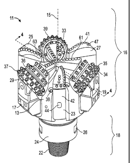
subterranean materials in a formation in the highly stressed leading portions
during
drilling operations, thereby easing the burden on the cutting elements of both
the
primary and secondary fixed cutting blades,
[0074]In the embodiments of the inventions illustrated in FIGS. 1, 2 and 3,
rolling
cone cutters 29, 31, 33 are illustrated in a non-limiting arrangement to be
angularly
spaced approximately 120 degrees apart from each other (measured between their
axes of rotation). The axis of rotation of each rolling-cutter 29, 31, 33
intersecting
the axial center 15 of bit body 13 of hybrid bit 11, although each or all of
the rolling
cone cutters 29, 31, 33 may be angularly skewed by any desired amount and (or)
laterally offset so that their individual axes do not intersect the axial
center of bit
body 13 or hybrid bit 11. By way of illustration only, a first rolling cone
cutter 29
-19-
CA 02855947 2014-05-14
WO 2013/074788
PCT/US2012/065277
may be spaced apart approximately 58 degrees from a first primary fixed blade
23
(measured between the axis of rotation of rolling cutter 29 and the centerline
of
fixed blade 23 in a clockwise manner in FIG. 3) forming a pair of cutters, A
second
rolling cone cutter 31 may be spaced approximately 63 degrees from a second
primary fixed blade 25 (measured similarly) forming a pair of cutters; and, a
third
rolling cone cutter 33 may be spaced approximately 53 degrees apart from a
third
primary fixed blade 27 (again measured the same way) forming a pair of
cutters.
[0075]The rolling cone cutters 29, 30, 31 are typically coupled to a generally
central spindle or similar bearing assembly within the cone cutter body, and
are in
general angular, or linear alignment with the corresponding secondary fixed
cutting
blades, as will be described in more detail below. That is, each of the
respective
secondary fixed cutting blades extend radially outward from substantially
proximal
the axial centerline 15 of the drill bit towards the periphery, and terminate
proximate
Is (but not touching, a space or void 90 existing between the terminal end
of the
secondary fixed cutting blade and the apex of the cone cutter) to the apex, or
top
end 30, of the respective rolling cone cutters, such that a line drawn from
and
perpendicular to the centerline 15 would pass through substantially the center
of
each secondary fixed cutting blade and substantially the center of each
rolling cone
2(3 cutter aligned with a respective secondary fixed cutting blade. The
truncated, or
frustoconical, rolling cone cutters 29, 30, 31 shown in the figures, and as
seen most
clearly in FIG. 3, generally have a top end 30 extending generally toward the
axial
centerline 15, and that in some embodiments can be truncated compared to a
typical roller cone bit. The rolling cutter, regardless of shape, is adapted
to rotate
around an inner spindle or bearing assembly when the hybrid drill bit 11 is
being
rotated by the drill string through the shank 24. Additionally, and in
relation to the
use of a saddle-pin design such as described and shown in FIGS. 12 and 14-16,
when a central bearing pin or spindle 670 is used to connect a secondary fixed
cutting blade to a rolling cone cutter, the terminal end of the secondary
fixed
cutting blade proximate to the apex or top end 30 of the respective rolling
cone
cutter to which it is aligned may optionally be widened to have a diameter
(measured between the leading "L" and terminal "T" edges) that is
substantially the
same as the diameter of the top end 30 of the truncated rolling cone cutter.
Such
-20-
CA 02855947 2014-05-14
WO 2013/074788
PCT/US2012/065277
an arrangement allows for the optional addition of further rows of cutting
elements
on the rolling cone cutter, and the widened connection point acts to reduce
balling
of cuttings during bit operation.
[0076]As best seen in the cross-sectional view of FIG. 4, bit body 13
typically
includes a central longitudinal bore 80 permitting drilling fluid to flow from
the drill
string into bit 11. Body 13 is also provided with downwardly extending flow
passages 81 having ports or nozzles 38 disposed at their lowermost ends. The
flow passages 81 are preferably in fluid communication with central bore 80.
Together, passages 81 and nozzles 38 serve to distribute drilling fluids
around a
cutting structure via junk slots, such as towards one of the roller cones or
the
leading edge of a fixed blade and/or associated cutter, acting to flush away
formation cuttings during drilling and to remove heat from bit 11.
15 [0077]Referring again to FIGS. 1, 2 and 3, the working end 16 of
exemplary drill bit
11 includes a plurality of fixed cutting blades which extend outwardly from
the face
of bit 11. In the embodiment illustrated in FIGS. 1, 2 and 3, the drill bit 11
includes
three primary fixed cutting blades 23, 25, 27 circumferentially spaced-apart
about
bit axis 15, and three secondary fixed cutting blades 61, 63, 65
circumferentially
zo spaced-apart about and radiating outward from bit axis 15 towards the
respective
rolling cone cutters 29, 31, 33, at least one of the fixed cutting blades
being in
angular alignment with at least one of the rolling cone cutters. In this
illustrated
embodiment, the plurality of fixed cutting blades (e.g., primary fixed cutting
blades
23, 25, 27 and secondary fixed cutting blades 61, 63, 65) are generally
uniformly
25 angularly spaced on the bit face of the drill bit, about central
longitudinal bit axis 15.
In particular, each primary fixed cutting blade 23, 25, 27 is generally being
spaced
an amount ranging from about 50 degrees to about 180 degrees, inclusive from
its
adjacent primary fixed cutting blade. For example, in the embodiment
illustrated
generally in FIGS. 11-12, the two primary cutting blades 623, 625 are spaced
substantially opposite each other (e.g., about 180 degrees apart). In other
embodiments (not specifically illustrated), the fixed blades may be spaced non-
uniformly about the bit face. Moreover, although exemplary hybrid drill bit 11
is
shown as having three primary fixed cutting blades 23, 25, 27 and three
secondary
-21-
CA 02855947 2014-05-14
WO 2013/074788
PCT/US2012/065277
fixed blades 61, 63, 65, in general, bit 11 may comprise any suitable number
of
primary and secondary fixed blades.
[0078] As one non-limiting example, and as illustrated generally in FIG. 6,
drill bit
211 may comprise two primary fixed blades 225, 227, two secondary fixed blades
261, 263 extending from the axial centerline 215 of the bit 211 towards the
apex
230 of two rolling cone cutters which are spaced substantially opposite each
other
(e.g., approximately 180 degrees apart). As is further shown in this figure,
drill bit
211 includes two tertiary blades 291, 293 which may or may not be formed as
part
of the secondary fixed cutters 261, 263, and which extend radially outward
from
substantially proximal the axial centerline 215 of the drill bit 211 towards
the
periphery of the bit.
[00791Another non-limiting example arrangement of cutting elements on a drill
bit
ei in accordance with the present disclosure is illustrated generally in
FIG. 7. As
shown therein, drill bit 311 includes three rolling cone cutters 331, 333, 335
at the
outer periphery of the bit and directed inward toward the axial centerline 315
of bit
311. The drill bit 311 further includes three secondary fixed blades 361, 363,
365
extending from the axial centerline 315 of the bit towards the apex 230 of the
three
rolling cone cutters 331, 333, 335. Also shown are four primary fixed blade
cutters
321, 323, 325, 327 extending from the periphery of the drill bit 311 towards,
but not
into, the cone region or near the center axis 315 of the bit. As is further
shown in
the alternative arrangement of FIG. 7, the three rolling cone cutters are
oriented
such that cone cutters 331 and 333 and cone cutters 333 and 335 are spaced
approximately equal distance apart from each other, e.g., about 85 - 110
degrees
(inclusive). Cone cutters 335 and 331 are spaced approximately 100 - 175
degrees apart, allowing for the inclusion of an additional primary fixed
cutting blade,
325 to be included in the space between cone cutters 335 and 331 and adjacent
to
primary fixed cutting blade 323. In a further, non-limiting example, as shown
in
3o FIG_ 8, a drill bit 411 in accordance with the present disclosure may
include four
rolling cone cutters 431, 433, 435, 437, four primary fixed cutting blades
421, 423,
425, 427, and four secondary fixed cutting blades 461, 463, 465, 467, As with
other embodiments of the present disclosure, the secondary fixed cutting
blades
CA 02855947 2014-05-14
WO 2013/074788
PCT/US2012/065277
461, 463, 465, 467 extend radially outward from substantially proximal the
axial
centerline 415 of the drill bit 411, in in substantial linear alignment with
each,
respective rolling cone cutter 4311 433, 435, 437.
,s [0080] With continued reference to FIGS. 1, 2 and 3, primary fixed
cutting blades
23, 25, 27 and secondary fixed cutting blades 61, 63, 65 are integrally formed
as
part of, and extend from, bit body 13 and bit face 10. Primary fixed cutting
blades
23, 25, 27, unlike secondary fixed cutting blades 61, 63, 65, extend radially
across
bit face 10 from the a region on the bit face outwards toward the outer
periphery of
us the bit, and (optionally) longitudinally along a portion of the
periphery of drill bit 11.
As will be discussed in more detail herein, primary fixed cutting blades 23,
25, 27
can extend radially from a variety of locations on the bit face 10 toward the
periphery of drill bit 11, ranging from substantially proximal the central
axis 15 to
the nose region outward, to the shoulder region outward, and to the gage
region
is outward, and combinations thereof. However, secondary fixed cutting
blades 61,
63, 65, while extending from substantially proximal central axis 15, do not
extend to
the periphery of the drill bit 11. Rather, and as best seen in the top view in
FIG. 3
showing an exemplary, non-limiting spatial relationship of the rolling cutters
to the
primary and secondary fixed cutting blades and the rolling cone cutters (and
their
respective cutting elements mounted thereon), primary fixed cutting blades 23,
25,
27 extend radially from a location that is a distance "D" away from central
axis 15
toward the periphery of bit 11. The distances "D" may be substantially the
same
between respective primary fixed cutting blades, or may be un-equivalent, such
that
the distance "D" between a first primary fixed cutting blade is longer or
shorter than
the distance "D" between a second (and/or third) primary fixed cutting blade.
Thus,
as used herein, the term "primary fixed blade" refers to a blade that begins
at some
distance from the bit axis and extends generally radially along the bit face
to the
periphery of the bit. Regarding the secondary fixed cutting blades 61, 63, 65,
compared to the primary fixed blades, extend substantially proximate to
central axis
.10 15 than primary fixed cutting blades 23, 25, 27, and extend outward in
a manner
that is in substantial angular alignment with the top end 30 of the respective
rolling
cone cutters 29, 31, 33. Thus, as used herein, the term "secondary fixed
blade"
refers to a blade that begins proximal the bit central axis or within the
central face
-23-
CA 02855947 2014-05-14
WO 2013/074788
PCT/US2012/065277
of the drill bit and extends generally radially outward along the bit face
toward the
periphery of the bit 11 in general angular alignment with a corresponding,
proximal
rolling cone cutter. Stated another way, secondary fixed blades 61, 63, 65 are
arranged such that the extend from their proximal end (near the axial
centerline of
the drill bit) outwardly towards the end- or top-face 30 of the respective
rolling
cutters, in a general axial or angular alignment, such that the distal end
(the
outermost end of the secondary fixed blade, extending towards the outer or
gage
surface of the bit body) of the secondary fixed blades 61, 63, 65 are
proximate, and
in some instances joined with, the end-face 30 of the respective roller
cutters to
o which they approach. As further shown in FIG. 3, primary fixed blades 23,
25, 27
and secondary fixed blades 61, 63, 65, as well as rolling cone cutters 29, 31,
33,
may be separated by one or more drilling fluid flow courses 20. The angular
alignment line "A" between a secondary fixed blade and a rolling cone may be
substantially aligned with the axial, rotational centerline of the rolling
cone, or
15 alternatively and equally acceptable, may be oriented as shown in FIG.
3, wherein
the roller cone and the secondary fixed blade cutters are slightly offset
(e.g., within
about 10) from the axial centerline of the rolling cone.
(0081]As described above, the embodiment of drill bit 11 illustrated in FIGS.
1, 2
20 and 3 includes only three relatively longer (compared to the length of
the secondary
fixed blades) primary fixed blades (e.g., primary blades 23, 25, 27). As
compared
to some conventional fixed cutter bits that employ three, four, or more
relatively
long primary fixed cutter blades, bit 11 has fewer primary blades. However, by
varying (e.g., reducing or increasing) the number of relatively long primary
fixed
2$ cutting blades, certain of the embodiments of the present invention may
improve
the rate of penetration (ROP) of bit 11 by reducing the contact surface area,
and
associated friction, of the primary fixed cutter blades.
[00821 Referring again to FIG. 4, an exemplary cross-sectional profile of
drill bit 11
is shown as it would appear if sliced along line 4-4 to show a single rotated
profile.
For purposes of clarity, backup all of the fixed cutting blades and their
associated
cutting elements are not shown in the cross-sectional view of FIG. 4,
-24-
CA 02855947 2014-05-14
WO 2013/074788
PCT/US2012/065277
[0083] In the cross-sectional profile, the plurality of blades of bit 11
(e.g., primary
fixed blades 23, 25, 27 and secondary fixed blades 61, 63, 65) include blade
profiles 91. Blade profiles 91 and bit face 10 may be divided into three
different
regions labeled cone region 94, shoulder region 95, and gage region 96. Cone
region 94 is concave in this embodiment and comprises the inner most region of
bit
11 (e.g., cone region 94 is the central most region of bit 11). Adjacent cone
region
94 is shoulder (or the upturned curve) region 95. In this embodiment, shoulder
region 95 is generally convex. The transition between cone region 94 and
shoulder
region 95. typically referred to as the nose or nose region 97, occurs at the
axially
outermost portion of composite blade profile 91 where a tangent line to the
blade
profile 91 has a slope of zero. Moving radially outward, adjacent shoulder
region
95 is gage region 96, which extends substantially parallel to bit axis 15 at
the
radially outer periphery of composite blade profile 91. As shown in composite
blade profile 91, gage pads 42 define the outer radius 93 of drill bit 11. In
this
embodiment, outer radius 93 extends to and therefore defines the full gage
diameter of drill bit 11. As used herein, the term "full gage diameter" refers
to the
outer diameter of the bit defined by the radially outermost reaches of the
cutter
elements and surfaces of the bit.
[00841Still referring to FIG. 4, cone region 94 is defined by a radial
distance along
the "x-axis" (X) measured from central axis 11. It is to be understood that
the x-axis
is perpendicular to central axis 15 and extends radially outward from central
axis
15. Cone region 94 may be defined by a percentage of outer radius 93 of drill
bit
11. In some embodiments, cone region 94 extends from central axis 15 to no
more
than 50% of outer radius 93. In select embodiments, cone region 94 extends
from
central axis 15 to no more than 30% of outer radius 93. Cone region 24 may
likewise be defined by the location of one or more primary fixed cutting
blades (e.g.,
primary fixed cutting blades 23, 25, 27). For example, cone region 94 extends
from
central axis 15 to a distance at which a primary fixed cutting blade begins
(e.g.,
distance "D" illustrated in FIG. 3). In other words, the outer boundary of
cone
region 94 may coincide with the distance "Er at which one or more primary
fixed
cutting blades begin. The actual radius of cone region 94, measured from
central
axis 15, may vary from bit to bit depending on a variety of factors including,
without
-25-
CA 02855947 2014-05-14
WO 2013/074788
PCT/US2012/065277
limitation, bit geometry, bit type, location of one or more secondary blades
(e.g.,
secondary blades 61, 63, 65), location of backup cutter elements 51, or
combinations thereof. For instance, in some cases drill bit 11 may have a
relatively
flat parabolic profile resulting in a cone region 94 that is relatively large
(e.g., 50%
of outer radius 93). However, in other cases, bit 11 may have a relatively
long
parabolic profile resulting in a relatively smaller cone region 94 (e.g., 30%
of outer
radius 93).
[0085] Referring now to FIG. 5, a schematic top view of drill bit 11 is
illustrated. For
purposes of clarity, nozzles 38 and other features on bit face 10 are not
shown in
this view. Moving radially outward from bit axis 15, bit face 10 includes cone
region
94, shoulder region 95, and gage region 96 as previously described. Nose
region
97 generally represents the transition between cone region 94 and shoulder
region
95. Specifically, cone region 94 extends radially from bit axis 15 to a cone
radius
1t5 Rc, shoulder region 95 extends radially from cone radius Rc to shoulder
radius Rs,
and gage region 96 extends radially from shoulder radius Rs to bit outer
radius 93.
[0086] Secondary fixed cutting blades 61, 63, 65 extend radially along bit
face 10
from within cone region 94 proximal bit axis 15 toward gage region 96 and
outer
radius 93, extending approximately to the nose region 97, proximate the top
face
30 roller cone cutters 29, 31, 33. Primary fixed cutting blades 23, 25, 27
extend
radially along bit face 10 from proximal nose region 97, or from another
location
(e.g., from within the cone region 94) that is not proximal bit axis 15,
toward gage
region 96 and outer radius 93. In this embodiment, two of the primary fixed
cutting
'25 blades 23 and 25, begin at a distance "D" that substantially coincides
with the outer
radius of cone region 94 (e.g., the intersection of cone region 94 and should
region
95). The remaining primary fixed cutting blade 27, while acceptable to be
arranged
substantially equivalent to blades 23 and 25, need not be, as shown. In
particular,
primary fixed cutting blade 27 extends from a location within cone region 94,
but a
distance away from the axial centerline 15 of the drill bit, toward gage
region 96
and the outer radius. Thus, primary fixed cutting blades can extend inwards
toward
bit center 15 up to or into cone region 94. In other embodiments, the primary
fixed
cutting blades (e.g., primary blades 23, 25, 27) may extend to and/or slightly
into
-26-
CA 02855947 2014-05-14
WO 2013/074788
PCT/US2012/065277
the cone region (e.g., cone region 94). In this embodiment as illustrated,
each of
the primary fixed cutting blades 23, 25 and 27, and each of the roller cone
cutters
29, 31, 33 extends substantially to gage region 96 and outer radius 93.
However,
in other embodiments, one or more primary fixed cutting blades, and one or
more
roller cone cutters, may not extend completely to the gage region or outer
radius of
the drill bit.
[0087] With continued reference to FIG. 5, each primary fixed cutter blade 23,
25,
27 and each secondary fixed cutter blade 61, 63, 65 generally tapers (e.g.,
becomes thinner) in top view as it extends radially inwards towards central
axis 15.
Consequently, both the primary and secondary fixed cutter blades are
relatively thin
proximal axis 15 where space is generally limited circumferentially, and widen
as
they extend outward from the axial center 15 towards gage region 96. Although
primary fixed cutter blades 23, 25, 27 and secondary fixed cutter blades 61,
63, 65
extend linearly in the radial direction in top view, in other embodiments, one
or
more of the primary fixed blades, one or more of the secondary fixed blades,
or
combinations thereof may be arcuate (concave or convex) or curve along their
length in top view.
(0088] With continued reference to FIG. 5, primary fixed blade cutter elements
41,
43, 45 are provided on each primary fixed blade 23, 25, 27 in regions 94, 951
96,
and secondary fixed cutter elements 40 are provided on each secondary fixed
cutter blade in regions 94, 95, and 97. However, in this embodiment, backup
cutter
elements 47, 49 are only provided on primary fixed cutter blades 23, 25, 27
(i.e., no
23 backup cutter elements are provided on secondary fixed cutter blades 61,
63, 65).
Thus, secondary fixed cutter blades 61, 63, 65, and regions 94 and 97 of
primary
fixed cutter blades 23, 25, 27 of bit 11 are substantially free of backup
cutter
elements.
zio [00893A further alternative arrangement between fixed cutter blades and
roller
cutters in accordance with the present disclosure is illustrated in FIGS. 9A
and 9B.
Therein, a drill bit 511 is shown which includes, on its working end, and
extending
upwardly from bit face 510 in the direction of the central axis 515 of the
bit, four
-27-
CA 02855947 2014-05-14
WO 2013/074788
PCT/US2012/065277
secondary fixed cutter blades 521, 523, 525, 527 having a plurality of fixed
blade
cutter cutting elements 540 attached to at least the leading edge thereof
(with
respect to the direct of rotation of the bit during operation), and four
roller cone
cutters 531, 533, 535, 537 having a plurality of roller cone cutting elements
540
attached thereto. Each of the four secondary fixed cutter blades (521, 523,
525,
527) are arranged approximately 90 degrees apart from each other; similarly,
each
of the four roller cone cutters (531, 533, 535, 537) are arranged
approximately 90
degrees apart from each other, and in alignment with the central axis of each
the
respective secondary cutter blades. Each of the secondary fixed cutter blades
521,
io 523, 525, 527 extends radially outward from proximate the bit axis 516
towards
nose region 97 of bit face 510, extending substantially the extent of cone
region 94.
In a like manner, each of the four roller cone cutters 531, 533, 535, 537
extend
radially outward from approximately nose region 97 through shoulder region 95
and
gage region 96 towards outer radius 93 of drill bit 511. As
in previous
embodiments, top- or apex-face 530 of each of the roller cone cutters is
proximate
to, but not in direct contact with (a gap or void 90 being present) the
terminal,
furthest extending end of the secondary fixed blade cutter to which it is
substantially
angularly or linearly aligned,
2.0
[0090]The drill bits in accordance with the previously-described figures have
illustrated that the roller cone cutters are not in direct contact with the
distal end of
any of the secondary fixed cutter blades to which they are in alignment, a
space,
gap or void 90 being present to allow the roller cone cutters to turn freely
during bit
operation. This gap 90, extending between the top-face of each truncated
roller
cone cutter and the distal end (the end opposite and radially most distant
from the
central axis of the bit), is preferably sized large enough such that the gap's
diameter allows the roller cone cutters to turn, but at the same time small
enough to
prevent debris from the drilling operation (e.g., cuttings from the fixed
cutting blade
cutting elements, and/or the roller cone cutting elements) to become lodged
therein
mt and inhibit free rotation of the roller cone cutter. Alternatively, and
equally
acceptable, one or more of the roller cutter cones could be mounted on a
spindle or
linear bearing assembly that extends through the center of the truncated
roller cone
cutter and attaches into a saddle or similar mounting assembly either separate
from
-28-
CA 02855947 2014-05-14
WO 2013/074788
PCT/US2012/065277
or associated with a secondary fixed blade cutter. Further details of this
alternative
arrangement between the roller cutters and the secondary fixed blades are
shown
in the embodiments of the following figures.
[0091]Turning now to FIG. 10, a cross-sectional view of an alternative
arrangement
between roller cone cutter 29 and secondary fixed blade cutter 63, such as
illustrated in FIGS. 1, 2 and 3, is shown. In the cross-sectional view, the
apex end
face 30 of the rolling cutter 29 is proximate to, and substantially parallel
to, the
outer distal edge face 67 of secondary fixed blade cutter 63. In accordance
with
w one aspect of this embodiment, the roller cone cutter 29 and the
secondary fixed
blade 63 are proximate each other, but do not directly abut, there being a
space or
gap 90 therebetween allowing the roller cone cutter 29 to continue to turn
about its
central longitudinal axis 140 during operation. As further illustrated in the
cross-
sectional view of this embodiment, a saddle-type assembly between the
secondary
U fixed blade cutter 63 and the roller cone cutter 29 is shown in partial
cut-away view.
As shown therein, the roller cone cutter 29 includes a linear bearing shaft 93
having
a proximal end 95 and a longitudinally opposite distal end 97, and which
extends
along the central, axial axis 140 of the roller cone cutter, from the outer
edge of the
bit leg 17 inwardly through the central region of roller cutter 29, and into a
recess
20 69 formed within the distal face 67 of secondary fixed cutter blade 63.
That is, the
bearing shaft 93 extends through the roller cone cutter and projects into, and
is
retained within (via appropriate retaining means such as a threadable
receiving
assembly within recess 69 shaped to threadably mate with a male-threaded
distal
end 97 of bearing shaft 93) the distal face 67 of the secondary fixed blade
cutter.
The bearing shaft 93 may also be removably secured in place via an appropriate
retaining means 91. Accordingly, during operation, the rolling cutter turns
about
bearing shaft 93. This particular embodiment is useful when, for example,
rolling
cutter 29 needs to be replaced during bit operation, due to a more rapid rate
of
wear on the rolling cutters versus the fixed blades. In such a situation, the
user
may remove bearing shaft 93, thereby releasing the rolling cutter 29, and
insert a
new rolling cutter into place, thereby saving the time typically necessary to
remove
and replace worn rolling cutters on a bit face. While bearing shaft 93 is
illustrated
as being substantially cylindrical and of uniform diameter throughout its
length,
-29-
CA 02855947 2014-05-14
WO 2013/074788
PCT/US2012/065277
bearing shaft 93 may also be tapered in some aspects of the invention. Another
embodiment allows for a spindle 53 of a roller cone cutter to extend through
the
inner end of the roller cone and the extension of the spindle is secured,
either
directly or indirectly, to or within the secondary fixed cutting blade, to a
separate
saddle bearing mount assembly, or to or within the bit body 13. This is
illustrated in
FIGS. 11-16.
[0092] Fla 11 illustrates an isometric perspective view of a further exemplary
drill
bit 611 in accordance with embodiments of the present invention. FIG. 12
illustrates a top view of the drill bit of FIG. 11. FIG. 13 illustrates a
partial cross-
sectional view of a roller cone cutter assembly, secondary fixed blade, and
saddle
bearing assembly in accordance with FIGS. 11 and 12. FIG. 14 illustrates a
partial
cut-away view of the assembly of FIG. 13. FIG. 14 illustrates an exemplary
extended, pass-through spindle bearing 670. FIG. 15 illustrates a partial top
perspective view of a saddle bearing assembly. These figures will be discussed
in
combination with each other.
[0093] FIG. 11 is an isometric view of drill bit 611. FIG. 12 is atop view of
the same
hybrid drill bit. As shown in the figures, drill bit 611 includes a bit body
613. Bit
body 613 is substantially similar to the bit bodies previously described
herein,
except that the working (lower) end of the drill bit includes only two roller
cone
cutters 629, 631 attached to bit legs 617, 619 mounted to the bit body 610,
and two
fixed blade cutters 623, 625, although the figure is not meant to limit the
disclosure,
and combinations including three and four fixed cutter blades and roller cone
.23 cutters are envisioned. Both the roller cone cutters 629, 631 and the
fixed blade
cutters are arranged substantially opposite (approximately 180 degrees apart)
from
each other about central bit axis 615, and each include a plurality of roller
cutter
cutting elements 635, and fixed blade cutting elements 641, 643. The drill bit
further includes a shaped saddle mount assembly 660 proximate the central axis
615 of the drill bit and providing a means by which the spindle 616 extends
through
the roller cutter cones and is retained at its distal end. While the saddle
mount
assembly 660 is shown to be generally rectangular or downwardly tapered
towards
bit face 610 (FIG. 12), or cylindrical in shape (FIG. 16), the saddle mount
assembly
-30-
CA 02855947 2014-05-14
WO 2013/074788
PCT/US2012/065277
660 may be of any appropriate shape as dictated by the overall design of the
drill
bit, including the type of formation the bit will be used in, the number of
roller
cutters employed, and the number of primary and secondary fixed blade cutters
are
included in the overall bit design.
0094FIG.13, is a schematic drawing in sections with portions broken away
showing hybrid drill bit 611 with support arms 617, 619 and roller cutter cone
assemblies 629, 631 having pass-through bearing systems incorporating various
teachings of the present invention. Various components of the associated
bearing
systems, which will be discussed later in more detail, allow each roller cone
cutter
assembly 629, 631 to be rotatably mounted on its respective journal or spindle
670,
which passes through the interior region of the roller cutter cones 629, 231
and
into a shaped retaining recess 669.
(0095]Cutter cone assemblies 629, 631 of drill bit 611 may be mounted on a
journal or spindle 670 projecting from respective support arms 617, 619,
through
the interior of the roller cutter cone, and into a recess within saddle mount
assembly 660 and its distal end 671 using substantially the same techniques
associated with mounting roller cone cutters on standard spindle or journal 53
projecting from respective support arms 19 as discussed previously herein with
reference to FIG. 4. Also, a saddle mount assembly system incorporating
teachings of the present invention may be satisfactorily used to rotatably
mount
roller cutter cone assemblies 629, 631 on respective support arms 617, 619 in
substantially the same manner as is used to rotatably mount cutter cone
assemblies on respective support arms as is understood by those of skill in
the art.
0096] With continued reference to FIG. 13, each rolling cone cutter assembly
629
preferably includes generally cylindrical cavity 614 which has been sized to
receive
spindle or journal 670 therein. Each rolling cone cutter assembly 629 and its
respective spindle 670 has a common longitudinal axis 650 which also
represents
the axis of rotation for rolling cone cutter assembly 629 relative to its
associated
spindle 670. Various components of the respective bearing system include
machined surfaces associated with the interior of cavity 614 and the exterior
of
-31-
CA 02855947 2014-05-14
WO 2013/074788
PCT/US2012/065277
spindle 670. These machined surfaces will generally be described with respect
to
axis 650.
[0097] For the embodiments shown in FIGS. 13, 14, 15 and 16, each roller cone
cutter assembly is retained on its respective journal by a plurality of ball
bearings
632. However, a wide variety of cutter cone assembly retaining mechanisms
which
are well known in the art, may also be used with a saddle mount spindle
retaining
system incorporating teachings of the present invention. For the example shown
in
FIG. 13, ball bearings 632 are inserted through an opening in the exterior
surface of
kJ? the bit body or bit leg, and via a ball retainer passageway of the
associated bit leg
617, 619, Ball races 634 and 636 are formed respectively in the interior of
cavity
614 of the associated roller cone cutter cone assembly 629 and the exterior of
spindle 670.
[0098] Each spindle or journal 670 is formed on inside surface 605 of each bit
leg
617, 619. Each spindle 670 has a generally cylindrical configuration (FIG. 15)
extending along axis 650 from the bit leg. The spindle 670 further includes a
proximal end 673 which when the spindle 670 is inserted into bit 611 and
through
roller cone cutter 629, will be proximal to the interior of the appropriate
bit leg.
73) Opposite from proximal end 673 is distal end 671, which may be tapered
or
otherwise shaped or threaded so as to be able to mate with and be retained
within
a recess within saddle mount assembly 660. Axis 650 also corresponds with the
axis of rotation for the associated roller cone cutter 629, 631. For the
embodiment
of the present invention as shown in FIG. 13, spindle 670 includes first
outside
25 diameter portion 638, second outside diameter portion 640, and third
outside
diameter portion 642.
[0099] First outside diameter portion 638 extends from the junction between
spindle
670 and inside surface 605 of bit leg 617 to ball race 636. Second outside
diameter portion 640 extends from ball race 636 to shoulder 644 formed by the
change in diameter from second diameter portion 640 and third diameter portion
642. First outside diameter portion 638 and second outside diameter portion
640
have approximately the same diameter measured relative to the axis 650. Third
-32-
CA 02855947 2014-05-14
WO 2013/074788
PCT/US2012/065277
outside diameter portion 642 has a substantially reduced outside diameter in
comparison with first outside diameter portion 638 and second outside diameter
portion 540. Cavity 614 of roller cone cutter assembly 629 preferably includes
a
machined surface corresponding generally with first outside diameter portion
638,
second outside diameter portion 640, third outside diameter portion 642,
shoulder
644 and distal end portion 673 of spindle 670.
[00100] With continued reference to FIGS, 13, 14, and 15, first outside
diameter
portion 638, second outside diameter portion 640, third outside diameter
portion
642 and corresponding machined surfaces formed in cavity 614 provide one or
more radial bearing components used to rotatably support roller cone cutter
assembly 629 on spindle 670. Shoulder 644 and end 673 (extending above the top
face 630 of roller cone cutter 629 and into a recess 661 formed in bearing
saddle
660) of spindle 670 and corresponding machined surfaces formed in cavity 614
provide one or more thrust bearing components used to rotatably support roller
cone cutter assembly 629 on spindle 670. As will be understood by those of
skill in
the art, various types of bushings, roller bearings, thrust washers, and/or
thrust
buttons may be disposed between the exterior of spindle 670 and corresponding
surfaces associated with cavity 614. Radial bearing components may also be
referred to as journal bearing components, as appropriate.
[00101] With reference to FIGS. 13 and 14, the overall assembly of the pass
through spindle 670 into saddle assembly 660 can be seen. In particular, a
recess
661 is preferably formed into the body of the saddle assembly 660, the recess
being in axial alignment with the longitudinal, rotational axis 650 of the
roller cone
cutter 629. Recess 661 is shaped to receive distal end 673 of spindle 670. The
spindle 670 may be retained within recess 661 by a suitable retaining means
(screw threads, pressure retention, or the like) as appropriate to prevent
spindle
670 from rotating as the roller cone cutter 629 rotates during bit operation.
In an
alternative arrangement, however, distal end 673 of spindle 670 is shaped to
fit
readily within the machined walls of recess 661 of saddle assembly 660, which
may
further optionally include one or more radial bearings, so as to allow spindle
670 to
rotate freely about its longitudinal axis during bit operation as appropriate,
-33-
CA 02855947 2014-05-14
WO 2013/074788
PCT/US2012/065277
[00102] Other features of the hybrid drill bits such as back up cutters, wear
resistant surfaces, nozzles that are used to direct drilling fluids, junk
slots that
provide a clearance for cuttings and drilling fluid, and other generally
accepted
features of a drill bit are deemed within the knowledge of those with ordinary
skill in
the art and do not need further description, and may optionally and further be
included in the drill bits of the present invention.
[00103] Turning now to FIGS. 17-19, further alternative embodiments of the
io present disclosure are illustrated. As shown therein, the drill bit may
be a hybrid-
type reamer drill bit, incorporating numerous of the above-described features,
such
as primary and secondary fixed blade cutters, wherein one of the fixed cutters
extends from substantially the drill bit center towards the gage surface, and
wherein
the other fixed cutter extends from the gage surface inwardly towards the bit
center,
but does not extend to the bit center, and wherein at least one of the first
fixed
cutters abuts or approaches the apex of at least one rolling cone. FIG. 17
illustrates a bottom, working face view of such a hybrid reamer drill bit, in
accordance with embodiments of the present disclosure. FIG. 18 illustrates a
side,
cutaway view of a hybrid reamer drill bit in accordance with the present
disclosure.
FIG. 19 illustrates a partial isometric view of the drill bit of FIG. 17.
These figures
will be discussed in combination with each other.
[00104] As shown in these figures, the hybrid reamer drill bit 711 comprises a
plurality of roller cone cutters 729, 730, 731, 732 frustroconically shaped or
25 otherwise, spaced apart about the working face 710 of the drill bit.
Each of these
roller cone cutters comprises a plurality of cutting elements 735 arranged on
the
outer surface of the cutter, as described above. The bit 711 further comprises
a
series of primary fixed blade cutters, 723, 725, which extend from
approximately
the outer gage surface of the bit 711 inwardly towards, but stopping short of,
the
34) axial center 715 of the bit. Each of these primary fixed blade cutters
may be fitted
with a plurality of cutting elements 741, and optionally backup cutters 743,
as
described in accordance with embodiments described herein. The drill bit 711
may
further include one or more (two are shown) secondary fixed blade cutters 761,
763
-34-
CA 02855947 2014-05-14
WO 2013/074788
PCT/US2012/065277
which extend from the axial center 715 of the drill bit 711 radially outward
towards
roller cone cutters 730, 732, such that the outer, distal end 767 of the
secondary
fixed blade cutters 761, 763 (the end opposite that proximate the axial center
of the
bit) abuts, or is proximate to, the apex or top-face 730 of the roller cone
cutters.
The secondary fixed blade cutters 761, 763 are preferably positioned so as to
continue the cutting profile of the roller cone cutter to which they
proximately abut
at their distal end, extending the cutting profile towards the center region
of the drill
bit. A plurality of optional stabilizers 751 are shown at the outer periphery,
or in the
gage region, of the bit 711; however, it will be understood that one or more
of them
w may be replaced with additional roller cone cutters, or primary fixed
blade cutters,
as appropriate for the specific application in which the bit 711 is being
used.
Further, in accordance with aspects of the present disclosure, the rolling
cone
cutters are positioned to cut the outer diameter of the borehole during
operation,
and do not extend to the axial center, or the cone region, of the drill bit.
In this
manner, the rolling cone cutters act to form the outer portion of the bottom
hole
profile. The arrangement of the rolling cutters with the secondary fixed
cutters may
also or optionally be in a saddle type attachment assembly, similar to that
described in association with FIGs. 10 and 11, above.
20 [00105] FIG. 19 illustrates a
schematic representation of the
overlap/superimposition of fixed cutting elements 801 of fixed cutter blade
761 and
the cutting elements 803 of rolling cutter 732, and how they combine to define
a
bottom hole cutting profile 800, the bottom hole cutting profile including the
bottom
hole cutting profile 807 of the fixed cutter and the bottom hole profile 805
of the
25 rolling cutter. The bottom hole cutting profile extends from the
approximate axial
center 715 to a radially outermost perimeter with respect to the central
longitudinal
axis The circled region 809 is the location where the bottom hole cutting
coverage
from the roller cone cutting elements 803 stops, but the bottom hole cutting
profile
continues. In one embodiment, the cutting elements 801 of the secondary fixed
30 cutter blade forms the cutting profile 807 at the axial center 715, up
to the nose or
shoulder region, while the roller cone cutting elements 803 extend from the
outer
gage region of the drill bit 711 inwardly toward the shoulder region, without
overlapping the cutting elements of the fixed cutter, and defining the second
cutting
-35-
CA 02855947 2014-05-14
WO 2013/074788
PCT/US2012/065277
profile 805 to complete the overall bottom hole cutting profile 800 that
extends from
the axial center 715 outwardly through a "cone region", a "nose region", and a
"shoulder region" (see FIG. 5) to a radially outermost perimeter or gage
surface
with respect to the axis 715. In accordance with other aspects of this
embodiment,
at least part of the roller cone cutting elements and the fixed blade cutter
cutting
elements overlap in the nose or shoulder region in the bit profile.
[00106] Other and further embodiments utilizing one or more aspects of the
inventions described above can be devised without departing from the spirit of
io Applicant's invention. For example, combinations of
bearing assembly
arrangements, and combinations of primary and secondary fixed blade cutters
extending to different regions of the bit face may be constructed with
beneficial and
improved drilling characteristics and performance. Further, the various
methods
and embodiments of the methods of manufacture and assembly of the system, as
well as location specifications, can be included in combination with each
other to
produce variations of the disclosed methods and embodiments. Discussion of
singular elements can include plural elements and vice-versa.
[00107] The order of steps can occur in a variety of sequences unless
otherwise
29 specifically limited. The various steps described herein can be combined
with other
steps, interlineated with the stated steps, and/or split into multiple steps.
Similarly,
elements have been described functionally and can be embodied as separate
components or can be combined into components having multiple functions.
[00108] The inventions have been described in the context of preferred and
other
embodiments and not every embodiment of the invention has been described.
Obvious modifications and alterations to the described embodiments are
available
to those of ordinary skill in the art. The disclosed and undisclosed
embodiments
are not intended to limit or restrict the scope or applicability of the
invention
conceived of by the Applicants, but rather, in conformity with the patent
laws,
Applicants intend to fully protect all such modifications and improvements
that
come within the scope or range of equivalent of the following claims.