Note: Descriptions are shown in the official language in which they were submitted.
NEEDLE BIOPSY DEVICE WITH EXCHANGEABLE NEEDLE AND INTEGRATED
NEEDLE PROTECTION
TECHNICAL FIELD
The present disclosure generally relates to the biopsy devices, and more
particularly,
needle biopsy devices for collecting tissue, fluid, and cell samples in
conjunction with
procedures such as endoscopic ultrasound or endoscopic bronchial ultrasound.
BACKGROUND INFORMATION
Endoscopic ultrasounds have been used for more than twenty five years within
the field
of medicine. These procedures allow clinicians to scan, locate and identify
individual layers of
the gastrointestinal (GI) tract and determine the location of individual
mucosal and submucosal
layers. As a result, appropriate therapeutic modes of treatment for
malignancies and various
abnormalities may be determined.
Endoscopic Ultrasound-Guided Fine-Needle Aspiration ("EUS ¨ FNA") and
Endobronchial Ultrasound-Guided Fine-Needle Aspiration ("EBUS ¨FNA") are
currently
standard modes of treatment in the field of GI Endoscopy and Bronchoscopy with
high yields of
sensitivity and specificity in the management of indications / diseases such
as esophageal cancer,
1
CA 2856060 2019-02-07f
CA 02856060 2014-05-15
WO 2013/074653 PCT/US2012/065049
pancreatic cancer, liver mass, non-small cell lung cancer, pancreatic mass,
endobronchial mass,
and intra-abdominal lymph nodes.
A typical endoscopic ultrasound procedure consists of several steps. First, a
clinician
sedates a patient and inserts a probe via esophagogastroduodenoscopy into the
patient's stomach
and duodenum. Second, an endoscope is passed through the patient's mouth and
advanced to the
level of the duodenum. Third, from various positions between the esophagus and
duodenum,
organs or masses outside the gastrointestinal tract are imaged to determine
abnormalities. If any
abnormalities that are present, the organs and/or masses can be biopsied
through the process of
"fine needle aspiration" (FNA).
Endoscopic ultrasounds and endoscopic bronchial ultrasounds through fine
needle
aspiration are presently the standard modes of diagnosis and/or treatment in
the field of
gastrointestinal endoscopy and bronchoscopy. These procedures traditionally
result in high
yields of sensitivity and specificity in the management of indications of
diseases such as
esophageal cancer, pancreatic cancer, liver mass, non-small cell lung cancer,
pancreatic mass,
endobronchial mass, and intra-abdominal lymph nodes.
An endoscopic ultrasound through fine needle aspiration requires a device that
is attached
to the luer port or working channel of a typical echoendoscope. Prior art
devices utilize a series
of push and pull handles to control the axial movement of the catheter shaft
of the device and the
depth of needle penetration. These devices, however, suffer from several
drawbacks.
One primary drawback of current FNA devices, concerns the lack of "Needle Safe
Preventative" design features which protect the end user from inadvertent
needle penetration and
the transfer of blood-borne pathogens from patient subject to attending
medical staff (Ref: The
Needle-stick Safety and Prevention Act (HR 5178) ¨ OSHA Regulation).
One of the primary issues still facing the medial device industry concerns the
propensity
for "Needle Stick". The Occupational Health and Safety Administration (OSHA)
has warned
that most needle destruction devices (NDDs) are "not compliant" with the
Bloodborne Pathogens
Standard, which are defined as "...controls (e.g., sharps disposal containers,
self-sheathing
needles, safer medical devices, such as sharps with engineered sharps injury
protection and
needleless systems) that isolate or remove the bloodbome pathogens hazard from
the
workplace." To comply with the OSHA standard, an employer must use engineering
and work
2
CA 02856060 2014-05-15
WO 2013/074653 PCT/US2012/065049
practice controls that will "eliminate or minimize employee exposure" (OSHA
Sec.
1910.1030(d)(2)(i)). OSHA's compliance directive explains that under this
requirement "the
employer must use engineering and work practice controls that eliminate
occupational exposure
or reduce it to the lowest feasible extent" (OSHA CPL 2-2.69 XIII, D.2.). The
employer's
exposure control plan is to describe the method the employer will use to meet
the regulatory
requirement. The plan must be reviewed and updated at least annually to
reflect changes in
technology that will eliminate or reduce exposure (Sec.1910.1030(c)(1)(iv)).
In the case of currently available FNA medical devices for both EUS and EBUS,
once the
sample has been aspirated from the desired anatomical location, the FNA
catheter is removed
from the echoendoscope and handed to the cytopathologist for sample extraction
/ preparation.
The user is instructed to "re-sheath" the needle (i.e. retract the needle into
the catheter sheath)
prior to detachment from the echoendoscope.
However, in many instances, this does not occur. As such, the needle sharp of
the device
is exposed during removal and transfer of the FNA device among medical staff
in the EUS /
EBUS suite with increased risk of "needle sticking" and blood borne pathogen
contamination /
exposure to same.
Therefore, a need exists for an improved device for use in endoscopic
ultrasound
procedures which address the lack of adherence to OSHA HR 5178, of current EUS
and EBUS
Fine Needle Aspiration devices.
Additionally, prior FNA devices in the art are not designed to individually
accommodate
needles of various diameters. Prior art fine needle aspiration device design
used in the field of
endoscopic ultrasound sample acquisition, are designed such that the sampling
needle is fully
integrated into the handle drive mechanism of the device. Specifically, in the
case of prior art
devices, the full system needle biopsy device (handle and integrated needle)
must be removed
from an endoscope during a procedure if a clinician chooses to utilize needles
of different sizes.
In this instance, the sample aspirate is removed from the needle of the device
with an en-suite
cytopathologist. The removal and prepping of the aspirated sample is time
consuming and results
in significant wait-time for the clinician between needle biopsy system passes
and sampling.
Another drawback of current FNA devices known in the art is that if the same
needle
biopsy system (as in the case of the prior art) is used throughout a procedure
for sampling at
3
CA 02856060 2014-05-15
WO 2013/074653 PCT/US2012/065049
numerous anatomical locations, the durability of both the needle and the
stylette components of
the device frequently become compromised (i.e. the needle and/or stylette
components may take
a "shape-set", kink or fracture). This results in a prolonging of the
procedure for the clinician,
hospital staff and prolonged periods of sedation for the patient with a
reduction in overall
.. procedural efficiency.
In this instance, the clinician must remove the needle biopsy system from the
endoscope;
open a second new device of different needle size; re-insert the new device
into the endoscope
and re-confirm position of the endoscope and needle relative to the intended
sampling site,
before acquiring the sample. In many instances, the device may be un-useable
after successive
needle passes. In this instance, no alternative exists for the clinician but
to utilize a new device
for the remainder of the procedure.
A further drawback of prior art fine needle biopsy devices used in endoscopic
and
endobronchial ultrasound procedures concerns the lack of flexibility provided
to the clinician
during a procedure.
Current EUS-FNA needle biopsy systems are commercially available in needle
sizes of
19, 22 and 25 gauge, with integrated handle and needle embodiments. In many
instances the
endoscopist or pulmonologist may desire to utilize a different size needle
during a procedure.
For example, a clinician may begin an endoscopic ultrasound or endobronchial
ultrasound
procedure with: (1) a device having a needle biopsy system with a diameter of
19 AWG; (2)
aspirate the sample; (3) remove the needle biopsy system from the endoscope;
(4) attach and
lock a new needle biopsy device (for example. 22AWG size) to the endoscope and
continue the
procedure. This results in a loss of procedural efficiency for the clinician,
patient and hospital
and also increases procedural costs through the utilization of a second, new
needle biopsy device.
Therefore, a need exists for an improved device for use in endoscopic
ultrasound and
endobronchial procedures which increases procedural efficiency, reduces
procedural costs and
improves procedural economics.
4
CA 02856060 2014-05-15
WO 2013/074653 PCT/US2012/065049
SUMMARY OF THE INVENTION
The invention provides a device for needle biopsy that includes a novel for a
delivery
handle system for interchangeably delivering needles of various sizes to a
biopsy site. The
delivery handle system has an adjustable length, a longitudinal axis defining
a lumen extending
therethrough, and includes a proximal handle member, a middle handle member
and a distal
handle member. The proximal handle member is slideably disposed over at least
a portion of
the middle handle member, the middle handle member is slideably disposed over
at least a
portion of the distal handle member. The proximal handle member includes an
inner hub
housing component having an internally cylindrical shape configured to
interchangeably receive
a needle subassembly that can be inserted into and withdrawn from the proximal
handle member.
The needle subassembly for insertion into and withdrawal from the delivery
handle
system includes an aspiration needle of a plurality of different sizes, each
needle having a
proximal end portion and a distal end portion. Preferably, the aspiration
needle ranges in size
from a 15 AWG to a 28 AWG aspiration needle (e.g., 19 AWG, 22 AWG or 25AWG). A
needle
luer and a needle hub are coupled to the proximal end portion of the needle,
the needle hub being
configured for coupling with the inner hub housing component of the proximal
handle member.
The needle subassembly further includes a needle protector subassembly
configured for coupling
to the distal end portion of the needle. The needle protector subassembly
includes a needle
protection hub having a lumen extending therethrough configured for receiving
the distal end
portion of the needle, a deformable 0-ring axially disposed within the lumen
of the needle
protection hub, and a tubular sheath defining a lumen extending from a distal
end of the needle
protection hub. The lumen of the tubular sheath is in communication with the
lumen of the
needle protection hub for receiving the needle when inserted into the needle
protection hub. In
one embodiment of the invention, the tubular sheath distally extending from
the needle protector
subassembly includes an internally tapering distal end.
In a preferred embodiment, the aspiration needle of the needle subassembly
includes a
collet surrounding the distal end portion of the needle. The collet has a
diameter larger than the
diameter of the deformable 0-ring of the needle protection hub, such that the
collet traverses the
deformable 0-ring when the needle is inserted into or withdrawn from the lumen
of the needle
protection hub, thereby locking the needle protector subassembly onto the
distal end portion of
5
CA 02856060 2014-05-15
WO 2013/074653 PCT/US2012/065049
the needle during insertion and withdrawal of the needle subassembly from the
delivery handle
system. The collet preferably chamfered at the proximal and distal ends to
provide a smooth
interface with the needle protector subassembly during needle exchange.
The aspiration needle of the needle subassembly also preferably includes a
distal tip
having four distinct angular bevel grinds, including a primary angle relative
to the needle shaft, a
secondary angle relative to the needle shaft, and a back-cut angle relative to
the secondary angle
for providing a smooth needle passage during needle insertion and withdrawal
during a biopsy
procedure.
The lumen extending through the delivery handle system includes an inner
hypotube
component at least partially disposed within the proximal handle member and an
outer hypotube
component disposed at least partially within the middle handle member. The
inner hypotube is
coupled to the outer hypotube and configured to longitudinally slide within
the outer hypotube
when the proximal handle member is distally advanced or proximally retracted
over the middle
handle member. The lumen further includes a tubular catheter sheath coupled to
a distal end of
the outer hypotube. The inner hypotube, outer hypotube and catheter sheath are
in constant
communication with each other.
Preferably, the catheter sheath includes a helically braided reinforcement
structure and
has an outer diameter ranging from 0.05 inches to 0.140 inches, and an inner
diameter ranging
from 0.05 inches to 0.120 inches. In certain embodiments, the catheter sheath
includes a tapered
distal tip having an outer and inner diameter that is smaller than the outer
and inner diameters of
the remaining length of the catheter sheath. In certain embodiments, the inner
diameter of the
distal tip ranges from 0.020 inches to 0.060 inches.
The delivery handle system of the invention further includes an inner handle
member
disposed within an inner portion of the middle handle member. The inner handle
member is
coupled to a proximal portion of the catheter sheath and a distal portion of
the outer hypotube,
such that the catheter sheath is distally extended into the distal handle
member when the middle
handle member is distally advanced over the distal handle member.
The delivery handle system of the invention further includes a first locking
mechanism
configured to prevent the proximal handle member from longitudinally sliding
over the middle
handle member, and a second locking mechanism configured to prevent the middle
handle
6
CA 02856060 2014-05-15
WO 2013/074653 PCT/US2012/065049
member from longitudinally sliding over the distal handle member. The first
locking mechanism
includes a first ring slideably disposed around at least a portion of the
middle handle member. A
screw is threaded within the first ring for locking the first ring in a fixed
position along the
middle handle member. The second locking mechanism includes a threaded insert
disposed
along a distal portion of the middle handle member. The threaded insert is
coupled to a screw
for tightening the threaded insert to lock middle handle member in a fixed
position along the
distal handle member.
The proximal handle member of the delivery handle system of the invention
includes an
inner retention collar disposed at a distal end of the inner hub housing
component. The inner
retention collar is configured to receive the needle protection hub coupled to
the needle. At least
a portion of the retention collar is recessed, and the deformable 0-ring
component is disposed
within the recessed portion for securing the needle protection hub within the
retention collar
upon insertion of the needle subassembly into the proximal handle member.
In certain embodiments. the 0-ring of the retention collar has a diameter
smaller than a
diameter of the needle protection hub, such that the needle protection hub
traverses the
deformable retention collar 0-ring when the needle subassembly is inserted
into or withdrawn
from the proximal handle member thereby locking the needle protector
subassembly onto the
proximal handle portion during insertion and withdrawal of the needle
subassembly from
delivery handle system.
The proximal handle member further includes a locking mechanism for releasably
locking the needle hub within the inner hub housing component of the proximal
handle member.
The locking mechanism includes a depressible latch component securely coupled
to the proximal
handle member. The latch includes a deflectable hinge coupled to a barb
component, that is
coupled to the inner hub housing component and disposed within an interior
portion of the
proximal handle member.
The needle hub of the needle subassembly includes an internal land ring for
interacting
with the deflectable hinge and barb component of the locking mechanism. The
internal land ring
traverses the deflectable hinge of the latch component when the needle
subassembly is inserted
into the lumen of the proximal handle member, thereby causing the deflectable
hinge to deflect
against the barb component during insertion. The deflectable hinge returns to
a home position
7
CA 02856060 2014-05-15
WO 2013/074653 PCT/US2012/065049
once the internal land ring has cleared the deflectable hinge to prevent the
needle hub from
moving backwards. The needle subassembly is released from the inner hub
housing component
of the proximal handle member by depressing the latching component to cause
the deflectable
hinge to deflect against the barb component to allow the internal land ring to
clear the deflectable
hinge and barb.
In certain embodiments, the inner hub housing component of the proximal handle
member includes a plurality of depressions spaced around an internal
circumference of the hub
housing component and the needle hub comprises a plurality of protrusions. The
plurality of
depressions is configured to receive the plurality of protrusions to prevent
the needle hub from
rotating relative to the hub housing component. Alternatively, the inner hub
housing component
includes a smooth internal circumference and the needle hub comprises a smooth
outer surface to
allow the needle hub rotate relative to the hub housing component.
In certain embodiments, the delivery handle system of the invention includes a
luer
holder coupled to a distal end of the distal handle member for coupling the
distal handle member
to a working channel port of an endoscope. In such embodiments, the luer
holder includes a luer
lock for locking the distal handle member in a fixed position relative to the
working channel of
the endoscope to prevent the delivery handle system from rotating about the
working channel.
These and other aspects of the invention are described in further detail in
the figures,
description, and claims that follow.
BRIEF DESCRIPTION OF DRAWINGS
In the following description, various embodiments of the present invention are
described
with reference to the following drawings that illustrate exemplary embodiments
of the invention.
Together with the description, the drawings serve to explain the principles of
the invention. In
the drawings, like structures are referred to by like numerals throughout the
several views. Note
that the illustrations in the figures are representative only, and are not
drawn to scale, the
emphasis having instead been generally placed upon illustrating the principles
of the invention
and the disclosed embodiments.
Figure 1 is an assembly drawing depicting the present invention incorporating
the
delivery system handle, catheter sheath and aspiration needle for the intended
field of use.
8
CA 02856060 2014-05-15
WO 2013/074653 PCT/US2012/065049
Figure 2 is a drawing of the aspiration needle sub-assembly of the present
invention.
Figure 3 is a cross sectional drawing of the needle protector embodiment of
the present
invention shown in Figure 2.
Figure 4 is a cross sectional drawing of the proximal end of the aspiration
needle sub-
assembly shown in Figure 2
Figure 4.A is a drawing of an alternate preferred embodiment of the proximal
end of the
aspiration needle sub-assembly with strain relief; Figure 4.B is a cross
sectional drawing of the
proximal end of the aspiration needle sub-assembly with strain relief.
Figures 5.A. through 5.D depict various enlarged views of a thumb latch
component
included in the proximal portion of the delivery system handle of the
invention.
Figure 5 is a cross sectional drawing of the delivery system handle of the
present
invention.
Figure 6 is an enlarged view of encircled Portion A shown in Figure 5, and
depicts a
cross sectional drawing of the needle locking mechanism of the delivery system
handle of the
present invention.
Figure 7 is an enlarged view of encircled Portion B shown in Figure 5, and
depicts cross
sectional drawing of the needle extension length adjustment mechanism of the
delivery system
handle of the present invention.
Figure 8 is an enlarged view of encircled Portion C shown in Figure 5, and
depicts a cross
sectional drawing of the catheter sheath extension length adjustment mechanism
of the delivery
system handle of the present invention.
Figure 9 is an enlarged view of encircled Portion D shown in Figure 5, and
depicts a
cross sectional drawing of the distal end of the assembled delivery system
handle of the present
invention, incorporating the mechanism for attachment to the endoscope.
Figures 10.A through 10.0 depict exemplary embodiments of an echogenically
enhanced
region at the distal end of an aspiration needle for use in the devices of the
invention.
Figure 10 is a drawing of the distal end of the needle with mounted needle
collet.
Figure 11 is a drawing of the extreme distal end of the needle.
Figure 12 is a drawing of the bevel detail of the needle of the present
invention,
incorporating primary angle, secondary angle, tertiary and back-cut angle
elements.
9
CA 02856060 2014-05-15
WO 2013/074653 PCT/US2012/065049
Figure 13 is a cross sectional drawing of the bevel detail of the needle of
the present
invention, illustrating the tertiary angle of the grind detail.
Figure 14 is a cross sectional drawing of the proximal end of the needle
protector hub
sub-assembly.
Figure 15 is a drawing of the intended functionality of the needle protector
assembly.
Figure 16 is a drawing of the intended functionality of the needle protector
and aspiration
needle assemblies during needle exchange and more specifically, during needle
insertion.
Figure 17 is a drawing of the intended functionality of the needle protector
and aspiration
needle assemblies during needle exchange and more specifically, during needle
insertion and
locking in the device handle.
Figure 18 is a drawing of the locking functionality of the needle protector
and aspiration
needle sub-assemblies in the hub housing components of the device handle.
Figure 19 is a cross-sectional drawing of locking functionality between the
needle hub,
thumb latch and hub housing components.
Figure 20 is a drawing of the hub needle hub and hub housing with interlocking
capability to ensure non-rotation.
Figure 21 is an alternate embodiment of the present invention, to facilitate
rotation
between needle hub and hub housing components.
Figure 22 is a drawing of the intended functionality of the present invention
to withdraw
.. the aspiration needle sub-assembly from the delivery system handle during
needle exchange.
Figure 23 is a drawing of the intended functionality of the needle collet
during needle
exchange and more specifically, during needle extraction from the device
handle.
Figure 24 is a drawing of the intended functionality of the needle collet
during needle
exchange and more specifically, during needle extraction from the device
handle.
Figure 25 is a drawing of the needle protector sub-assembly secured to the end
of the
aspiration needle, and the intended functionality of the needle sheath of the
present invention.
Figure 26 is a drawing of the distal end of the aspiration needle sub-assembly
housed in
the catheter sheath of the delivery system of the present invention.
Figure 27 is a drawing of the distal end of the aspiration needle sub-assembly
extending
.. from the catheter sheath of the delivery system of the present invention.
CA 02856060 2014-05-15
WO 2013/074653 PCT/US2012/065049
Figure 28 is a drawing of the intended functionality of the present invention,
and more
specifically of the intended functionality of the catheter sheath of the
present invention.
Figure 29 is a drawing of the construction of the catheter sheath component of
the present
invention.
DETAILED DESCRIPTION
The invention provides a device for needle biopsy for collecting tissue,
fluid, and cell
samples in conjunction with procedures such as an endoscopic ultrasound (EUS)
or endoscopic
bronchial ultrasound (EBUS).
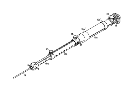
An exemplary embodiment of the proposed device assembly is illustrated in
Figure 1.
The device design consists of a handle mechanism (delivery system handle 10)
and aspiration
needle sub-assembly 15. The delivery system handle 10 includes a proximal
handle member 10a,
a middle handle member 10b, and a distal handle member 10c. The proximal,
middle and distal
handle members each include an inner lumen and are coupled together to define
a longitudinal
axis such that the inner lumens are in constant communication and extends
throughout the length
of the coupled handle members. Proximal handle member 10a is slideably
disposed over at least
a portion of the middle handle member 10b, and middle handle member 10b is
slideably
disposed over at least a portion of distal handle member 10c. The proximal
handle member 10a
includes proximal handle grip 10a1 a distal handle grip 10a2. The delivery
handle system 10
further includes an inner handle member 10d disposed within the inner lumen of
the middle
handle member 10b (shown in Figures 5 and 7). The delivery system handle 10
also
incorporates a catheter sheath 14 component coupled to the distal end of the
distal handle
member 10c. This component provides a conduit between the delivery system
handle 10 and the
target sampling site during the exchange of aspiration needles. The device
design is modular in
that the needle sub-assembly 15 can be detached from the proximal handle 10a
of the device for
each individual "pass" or aspirated sample taken by the endoscopist at the
site of the lesion or
abnormality.
The delivery system handle 10 incorporates two length adjustment features
actuated via
adjustment of two thumbscrew locking mechanisms. A threaded proximal
thumbscrew 12 and
locking ring 33 are moveably disposed around the middle handle member 10b; the
proximal
11
CA 02856060 2014-05-15
WO 2013/074653 PCT/US2012/065049
thumbscrew 12 is loosened to loosen locking ring 33, locking ring 33 is moved
distally along the
middle handle member 10b and tightened in the desired position along middle
handle member
10b via proximal thumbscrew 12 to allow the user to establish a set depth of
needle penetration
beyond the end of the catheter sheath 14. A threaded distal thumbscrew 13 is
transversely
disposed at the distal portion of the middle handle member 10b; the distal
thumbscrew 13 is
loosened to move the middle handle member 10b distally and/or proximally and
tightened to
allow the user to establish a set depth of catheter sheath 14 extension beyond
the end of the
endoscope.
The needle sub-assembly 15 consists of the needle shaft 21(which can range in
length
from 500 mm up to 2500 mm, but which more preferably ranges in length between
1640 mm to
1680 mm) and is beveled at the distal needle end to enhance tissue penetration
during sample
acquisition; needle hub 17; needle luer 18; needle collet 19; needle protector
sub-assembly 9;
stylette hub 20 and stylette shaft 22. The needle component itself can be
manufactured from a
number of metallic based (Stainless steel or alloys thereof; Nitinol or Alloys
thereof etc...) or
Polymeric Based materials including, but not limited to Poly-ether-ether
ketone, Polyamide,
Poyethersulfone, Polyurethane, Ether block amide copolymers, Polyacetal,
Polytetrafluoroethylene and / or derivatives thereof).
Figure 2 illustrates the aspiration needle sub-assembly 15 of the present
invention. This
sub-assembly is inserted into and removed from the lumen of the delivery
system handle 10 in
acquiring tissue samples. The sub-assembly 15 consists of a stylette hub 20
and stylette shaft 22
components which are securely locked on the needle luer 18 of the aspiration
needle via
conventional internal luer threads (as is know to persons skilled in the art).
The stylette hub 20
may be attached to the stylette shaft 22 via a number of processing techniques
such as adhesive
bonding or insert injection molding. The female luer of the aspiration needle
incorporates a
mating luer thread detail, onto which the stylette hub 20 may be tightened.
The needle luer 18
element of the present invention may be attached to the proximal end of the
needle shaft via a
number of processing techniques such as adhesive bonding or insert injection
molding.
The aspiration needle sub-assembly 15 also incorporates a needle collet 19
(previously
described as "needle protrusion(s) and shown in Figures 3 and 10 of
Applicant's co-pending
application (U.S. Serial No. 12/243,367, published as US2010/0081965). The
function of this
12
CA 02856060 2014-05-15
WO 2013/074653 PCT/US2012/065049
needle collet 19 is to (1) provide a means to center the needle shaft
component in the catheter
sheath of the delivery system during needle exchange (2) provide a mechanism
or securing and
locking the needle protector sub-assembly to the distal end of the aspiration
needle once the
needle has been unlocked and withdrawn from the delivery system handle. The
needle collet 19
of the present invention may be attached to the distal end of the needle shaft
21 via a number of
processing techniques such as adhesive bonding, laser welding, resistance
welding, or insert
injection molding. The needle collet 19 may be fabricated from metals
materials such as stainless
steel, nickel titanium or alloys thereof or polymer materials such as, but not
limited to,
Polyacetal, polyamide, poly-ether-block-amide, polystyrene. Acrylonitrile
butadiene styrene or
derivatives thereof. The needle collet 19 is located at a set point distance
from the extreme distal
end of the beveled needle. The distance from the extreme distal end of the
needle bevel to the
proximal collet position on the needle may be within the range of 6 cm to 12
cm but is more
preferably in the range of 7 cm to 9 cm and ore preferably is located 8 cm
from the end of the
needle. This ensures that when the needle is extended to it's maximum
extension distance relative
to the distal end of the catheter sheath (i.e. 8 cm), the collet 19 does not
exit the end of catheter
sheath 14.
Figures 3 and 14 illustrate the needle protection sub-assembly 9 design
embodiment of
the current invention, in the locked position at the distal end of the needle.
The needle protection
sub-assembly 9 consists of two needle protector (NP) hub halves (collectively
23), which are
adhesively bonded to each other, on the proximal end of the needle protector
(NP) sheath
component 24. Alternately, these NP hub halves 23 may be snap fit together or
may be insert
injection molded over the NP sheath 24 to provide a secure bond / attachment
between these
components in the assembly. The needle protection sub-assembly 9 also
incorporates a needle
protector (NP) hub 0-Ring component 25. This component resides in a recessed
cut-out in the
center of the assembled NP hub halves 23. This NP hub 0-Ring 25, in
conjunction with the
needle collet 19 which is securely attached to the distal end of the needle
shaft 21 of the sub-
assembly 9, provides a mechanism for locking the NP sub-assembly 9 onto the
end of the needle.
In this way, the bevel of the needle is protected, covered and shielded once
the needle has been
removed from the delivery system handle. It is desired that the NP sheath 24
of the present
13
CA 02856060 2014-05-15
WO 2013/074653 PCT/US2012/065049
invention be manufactured from a translucent polymer such as, but not limited
to polyurethane,
polyamide and derivatives thereof.
The needle hub 17 embodiment of the aspiration needle sub-assembly as shown in
Figure
2 and Figure 4 of the present invention, provides a mechanism which (1) locks
the aspiration
needle sub-assembly 15 into the delivery system handle 10 by means of the hub
housing 27 and
thumb latch 28 components (as will be described later in this disclosure) and
(2) provides a
means to lock the needle protection sub-assembly 9 embodiment shown in Figure
3, into the
delivery system device handle 10, as will be described later. As shown in
Figure 4, the needle
hub component 17 is securely attached to the needle luer 18 and needle shaft
21 components of
the aspiration needle sub-assembly 15. The needle hub element 17 of the
present invention may
be attached to the distal end of the needle luer component 18 via a number of
processing
techniques such as adhesive bonding or insert injection molding.
An alternate preferred embodiment of the proximal end of the aspiration needle
sub-
assembly 15 is shown in Figures 4.A and 4.B. This embodiment incorporates a
strain relief
component 26, which extends from the distal end of the needle luer component
18, through the
body of the needle hub component 17, to extend beyond the distal end of the
needle hub 17. This
tubular strain relief component 26 is intended to provide a more gradual
stiffness transition
between the needle hub 17 and needle shaft 21 components, particularly in the
case of smaller
needle gauge sizes (such as 22A WG and 25A WG). This strain relief component
26 may range
in length from 10 ram to 50 mm but is more preferably in the range of 25 ram
to 35 mm. The
diameter of this strain relief component 26 must be sufficiently small so that
it fits through the
proximal end of the needle protection sub-assembly 9 (as shown in Figure 3)
and does not impair
the ability for the NP sub-assembly 9 to slide back and forth on same. This
strain relief
component 26 may range in outer diameter from 0.020 inches to 0.060 inches but
is more
preferably in the range of 0.026 inches to 0.045 inches. This tubular strain
relief 26 may be
fabricated from metal based materials, such as but not limited to stainless
steel, nickel titanium
or alloys thereof or polymer materials such as, but not limited to,
Polyacetal, polyamide, poly-
ether-block-amide, polystyrene, Acrylonitrile butadiene styrene or derivatives
thereof.
Figure 5 is a sectional view of the delivery system handle 10 for the present
invention,
without the aspiration needle sub-assembly 15 loaded therein. Figure 6 (Detail
A from Figure 5)
14
CA 02856060 2014-05-15
WO 2013/074653
PCT/US2012/065049
illustrates a sectional view of the proximal end 10a of the assembled device
handle. This
proximal portion of the handle (also shown in Figure 16 and Figure 18)
contains elements to
ensure secure, yet releasable locking of the aspiration needle sub-assembly 15
in the delivery
system handle 10. The hub housing component 27 is secured to the proximal
delivery system
handle halves 10a via adhesive bonding or ultrasonic welding techniques. The
thumb latch
component 28 is securely locked into the hub housing component 27 via a one-
way keying
action. Once the thumb latch component 28 is inserted into the hub housing
component 27, the
thumb latch 28 cannot be disassembled and may only be moved in the transverse
direction to
actuate the assembled mechanism.
Figures 5A, 5B, 5D, and 5D depict various views of an exemplary embodiment of
the
thumb latch component 28 of the delivery system handle 10. The thumb latch
component 28
represents a mechanism to releasably lock the needle hub 17 of aspiration
needle sub-assembly
within the hub housing 27 of the proximal handle member 10a of the delivery
device. Thumb
latch 28 may be, for example, a push-button, that activates the use of a
deflectable hinge member
15 28a to provide for a return to the "home" position once external force
is not applied to release
thumb latch 28. Hinge member 28a can elastically deform to provide for the
opening and closing
of the "lock" during removal of the aspiration needle sub-assembly 15 from the
delivery system
handle 10. In one embodiment, thumb latch 28 incorporates an external coupler
housing 28b and
a push button design mechanism. FIGS. 5.d and 5.d illustrates thumb latch 28
in the CLOSED
and OPEN positions during a typical actuation cycle.
Referring to Figures 5.a and 5.b, thumb latch 28 and external coupler housing
28b may
be manufactured from a range of rigid, non-deformable, thermoplastic or
thermoset materials
such as, acrylonitrile butadiene styrene (ABS), styrene acrylonitrile (SAN),
polystyrene or rigid
derivatives thereof, polyamide, polyethylene, polyurethane, and polycarbonate.
In an
embodiment, the materials of manufacture have a durometer in the range of 35-
120 Shore D, but
more preferably in the range of 80-110 Shore D.
Hinge member 28a may be manufactured from a range of rigid, thermoplastic or
thermoset materials such as, acrylonitrile butadiene styrene (ABS), styrene
acrylonitrile (SAN),
polystyrene or rigid derivatives thereof, polyarnide, polyethylene,
polyurethane, and
polycarbonate. In an embodiment, the materials of manufacture shall be capable
of deformation
CA 02856060 2014-05-15
WO 2013/074653 PCT/US2012/065049
in bending under the application of an applied load, such as is encountered
during a typical
"Open and Close" cycle for the needle biopsy device without crazing, fatigue
or cracking.
The proximal portion of the proximal handle member 10a of the delivery system
handle
10, incorporates a retention collar 29 and a retention collar 0-ring component
30. The retention
collar component 29 resides in a cut out nest in the proximal handle half, and
is in
communication with inner hub housing component 27. The retention collar 29 is
a cylindrical
component, which is internally tapered and recessed to provide an internal,
recessed shelf. The
retention collar 0-ring component 30 resides in this recessed shelf and is
secured in position
through the assembly of both halves of the delivery system handle halves. The
purpose of this
.. retention 0-Ring component 30 is to provide a method to lock and maintain
the needle protector
hub sub-assembly 9 of the aspiration needle sub-assembly 15, securely in the
handle 10 of the
delivery system while the tissue sample site is being accessed by the
clinician, as described in
detail below. The functionality and operation of this retention collar 0-Ring
component 30 is the
same as described in Figures 41 and 42 and associated abstract of the
specification of
.. Applicant's co-pending patent application U.S. Serial No. 12/607.636
(published as
US2010/0121218).
As shown in Figure 6, the delivery system handle assembly 10 of the present
invention
incorporates an inner hypotube component 31. It is the design intent of this
component to
provide a conduit between the proximal handle member 10a of the delivery
system, and the outer
hypotube component 32 shown in Figure 7. The inner hypotube component 31 may
be fabricated
from metal based materials, such as but not limited to stainless steel, nickel
titanium or alloys
thereof or polymer materials such as, but not limited to, Polyacetal,
polyamide, poly-ether-block-
amide, polystyrene, Acrylonitrile butadiene styrene or derivatives thereof.
The inner hypotube 31
is secured to the assembled handle halves of the device via adhesive bonding
or insert injection
molding techniques. During needle advancement, the proximal handle member 10a
of the
delivery system is distally advanced, in order to advance the distal end of
the needle into the
desired tissue sampling site. When the proximal handle member 10a is distally
advanced, the
inner hypotube 31 is also advanced in unison in a distal direction. The inner
hypotube component
31 is in constant longitudinal communication with the outer hypotube component
32 and is
16
CA 02856060 2014-05-15
WO 2013/074653 PCT/US2012/065049
designed to telescope inside the outer hypotube component 32 at all times.
This ensures that
needle passage during needle exchange into and out of the delivery system, is
not impaired.
Referring now to Figure 7 (Detail B from Figure 5), a cross sectional view of
the distal
end of the proximal handle member 10a and the middle handle member 10b is
illustrated.
During a typical EUS FNA procedure, the locking ring component 33 is loosened
via proximal
thumbscrew 12, moved distally and set to a pre-established depth by the
clinician, dependent
upon depth of needle penetration required. Once the locking ring 33 has been
moved distally (via
the proximal thumbscrew) and locked to the required depth of penetration, the
proximal handle
member 10a of the delivery system is advanced. During advancement, the
proximal handle
member 10a moves in a longitudinal direction over the middle handle member 10b
and inner
handle member assembly 10d. The inner handle member 10d and middle handle
member 10b
components are securely bonded to each via adhesive bonding or ultrasonic
welding techniques
and remain in a stationary, locked position during needle advancement via
proximal handle 10a
actuation in a distal direction.
As shown in Figure 7, the outer hypotube component 32 is also in constant
communication with the catheter shaft component 14 of the delivery system. The
proximal end
of the catheter shaft component 14 is flared in an outward direction. The
distal end of the outer
hypotube component 32 is inserted into flared end of the catheter shaft 14 and
secured thereto via
adhesive bonding or insert injection molding techniques. The inner handle
member 10d is
bonded to both the proximal end of the catheter shaft 14/ outer hypotube 32
assembly via
adhesive bonding or insert injection molding techniques. In this way, the
inner hypotube 31,
outer hypotube 32 and catheter sheath 14 are in constant communication,
ensuring for smooth
needle passage during needle exchange. This design embodiment, also ensures
that the catheter
sheath 14 my be advanced through the distal handle member 10c as required.
Figures 8 and 9 illustrate the design assembly embodiments for catheter sheath
extension
length adjustment in the case of the present invention. Referring to Figure 8,
the distal end of the
middle handle member 10b incorporates a threaded insert 7 and distal
thumbscrew 13. The
catheter sheath extension distance beyond the end of the endoscope may be
adjusted by
loosening the distal thumbscrew 13 and advancing the middle handle member 10b
in a distal
17
CA 02856060 2014-05-15
WO 2013/074653 PCT/US2012/065049
direction over the distal handle member 10c. The distal handle member 10c and
middle handle
member 10b are in constant longitudinal communication with each other.
Referring to Figure 9, the distal end of the delivery system handle assembly
10 is
illustrated. The distal handle member 10c is secured to a recess in the distal
luer holder 6 via
adhesive bonding or ultrasonic welding techniques. The distal luer holder
component 6 is
securely attached to the scope luer lock component 5 via adhesive bonding or
insert injection
molding techniques. The distal handle member 10c is designed in such a way
that once the
device handle is attached to the working channel port of the endoscope, the
assembly cannot
rotate independently of assembled scope luer lock 5 and distal luer holder 6
components. Once
the entire delivery system handle 10 (as shown in Figures 1 and cross
sectional view Figure 5)
has been locked onto the endoscope via the scope luer lock 5, the catheter
sheath length and
needle penetration extension length may be established as previously
described.
Figure 10 is an illustration of the distal end of the aspiration needle of the
present
invention, with needle collet (referred to as "needle protrusions" in
Applicant's co-pending
patent application U.S. Serial No. 12/607,636, published as US2010/0121218)
secured on the
needle. It is preferable that the length of this needle collet 19 be in the
range of 2 mm to 10 mm,
but more preferably in the range of 3.5 mm to 5 mm. It is preferable that the
outer diameter of
the needle collet 19 be in the range of 0.030 inches to 0.080 inches, but more
preferably in the
range of 0.040 inches to 0.070 inches. This needle collet component 19 (see
also Figure 14 and
Figure 26) is also chamfered at the proximal and distal ends of same. It is
preferable that the
chamfer angle of the needle collet be in the range of 15 degrees to 80
degrees, but more
preferably in the range of 30 degrees to 60 degrees. This chamfer on both ends
of the needle
collet 19 is intended to provide smooth locking and unlocking with the needle
protector sub-
assembly 9 during needle exchanges.
As depicted in Figure 10, and Figures 10.A. through 10.0, the distal end of
the needle of
the present invention incorporates an embodiment to enhance the echogenic
signature of the
needle. In the case of the present invention, this echogenically enhanced
region 34 can be
fabricated by, but not limited to roughening the end of the needle over a pre-
defined length close
to proximal end of the needle bevel 35. It is preferable that the length of
this echogenically
enhanced region 34 be in the range of 2 mm to 20 mm, but is more preferably in
the range of 10
18
CA 02856060 2014-05-15
WO 2013/074653 PCT/US2012/065049
mm to 15 mm. In the case of the present invention, the echogenic enhanced
pattern is imparted to
the needle via a micro-blasting process which roughens the surface of the
needle over a specific
length, improving the visibility of the needle under endoscopic ultrasound.
In certain aspects of the invention, the echogenically enhanced region of the
needle is
.. achieved through the removal of material from the surface of the needle to
provide greater
reflectivity and strengthened reflected signal. It is contemplated that the
removal of material does
not, however, reduce the performance of the needle from a pushability
perspective or deter its
ability to acquire a desired sample.
Referring now to FIG. 10.A, a perspective view of an embodiment of a needle
600 is
.. presented. Needle 600 is comprised of a plurality of depressions 602.
Depressions 602 may be,
but are not limited to, circular, concave, cylindrical, helical, oval,
rectangular, and square
elements that take the form of indentations on the surface of needle 600.
Depressions 602 may be
arranged in a helical (spiral) fashion around the circumference of the distal
needle end. These
indentations may extend to the extreme end of the bevel or may end at a
specific distance from
the bevel of needle 600. The length of the distal end of needle 600 containing
these depressions
may be, for example, from one to twenty centimeters. In another embodiment,
the length is
between five to ten centimeters. Referring to FIGS. 10.B and 10.C, depression
602 have a
concave detail 604. Referring to FIGS. 10.D and 10.E, depressions 602 have a
square base edge
606. Referring to FIGS. 20F and 20G. depressions 602 have a hemispherical base
detail 608.
Referring now to FIG. 10.H, a perspective view of another embodiment of a
needle 610 is
presented. Needle 610 is comprised of elliptical depressions 612 around the
circumference of the
distal end of needle 610. Referring to FIG. 10.1, a perspective view of an
embodiment of a needle
614 having square depressions 616 is presented. Depressions 616 may extend to
the extreme end
of the bevel or may end at a specific distance from the bevel of needle 614.
Referring to FIGS.
10J and 10K, embodiments of needle 614 including spiral depressions 620 and
helical
depressions 622 are presented. Referring to FIG. 10.L, a depression 624 has a
concave detail.
Referring to FIG. 10.M, a depression 626 has a square base edge. Referring to
FIG. 10.N, a
depression 628 has a hemispherical base detail.
Referring now to FIG. 10.0, a diagram of ultrasound waves impinging upon a
needle
.. depression at angles of al 630 and (31 632 respectively are presented. In
an embodiment, a wave
19
CA 02856060 2014-05-15
WO 2013/074653
PCT/US2012/065049
strikes the base of the depression and is reflected upwards at angle of
reflection of a 2 634 and
p2 636 respectively, which are equal to the angles of incidence of al 630 and
pl 632
respectively. This reflected beam is reflected a second time off the adjacent
wall of the
depression at an angle of reflection of a3 638 and 133 640 respectively, which
are equal to the
angles of incidence, al 630 and (31 632 respectively and the angles of first
reflection a2 634 and
p2 636 respectively. In this manner, the reflected wave becomes reflected
along the same angle
of incidence as the initially propagated incident beam back to the transducer
of the ultrasound
device. In an embodiment, a square edge depression design may provide for more
efficient
remittance of ultrasound waves during the procedure.
Figures 11 and 12 are drawings of the distal end of the needle of the current
invention.
The distal end of the needle 35 of the current invention is beveled to enhance
the ability of the
needle to penetrate tissue during sample acquisition. The bevel detail 35 of
the present invention
incorporates four angular bevel grinds, which, in addition to enhancing tissue
penetration, also
ensure the smooth passage of the needle down the catheter sheath of the
delivery system during
.. needle exchange. Referring to Figure 12, the needle bevel grind of the
current embodiment
incorporates a primary angle ("A"), a secondary angle ("B"), a back-cut angle
("C") and tertiary
angles ("D"), as shown in Figure 11 It is preferable that the primary angle be
in the range of 10
degrees to 25 degrees, but more preferably in the range of 12 degrees to 18
degrees. It is
preferable that the secondary angle be in the range of 15 degrees to 35
degrees, but more
preferably in the range of 22 degrees to 28 degrees. It is preferable that the
tertiary angle be in
the range of 15 degrees to 35 degrees, but more preferably in the range of 22
degrees to 28
degrees. It is preferable that the back-cut angle be in the range of 15
degrees to 70 degrees, but
more preferably in the range of 25 degrees to 45 degrees.
During needle exchange, it is important that the aspiration needle (with pre-
loaded
stylette 2) can be passed through the internal diameter of the catheter sheath
14 without catching
on the internal wall of same. In order to achieve this, the bevel grind of the
current invention
incorporates a back-cut grind detail. This back-cut detail acts as a "bumper"
during needle
passage through the sheath. As the needle advances, the heel of the back-cut
comes in contact
with the internal diameter of the sheath and reduces the friction between
needle end 35 and
CA 02856060 2014-05-15
WO 2013/074653 PCT/US2012/065049
catheter sheath 14 components. In this way, the needle can be smoothly tracked
through the
catheter sheath to exit the end of the catheter sheath 14.
Figure 14 and Figure 15 illustrate the method of engagement and disengagement
between
the aspiration needle sub-assembly 15 with mounted collet 19 and the needle
protector ("NP")
sub-assembly 9. Referring to Figure 14, the NP hub 23 is locked onto the
needle collet 19 at the
distal end of the needle shaft 21 by inserting the shaft 21 into the NP hub
23. As the needle/NP
protector assembly is inserted into the handle of the delivery system, the
needle 21 and needle
collet 19 are advanced such that the needle collet 19 traverses the deformable
NP Hub 0-Ring
25. The internal diameter of the NP Hub 0-Ring 25 in the non-deformed state,
is smaller than the
outer diameter of the needle collet 19. Due to the soft durometer and elastic
nature of the NP
Hub 0-Ring 25, as the needle 21 and attached needle collet 19 are moved
distally, the NP 0-
Ring 25 deforms allowing the collet to traverse the NP 0-ring 25 under applied
longitudinal
force. Once the needle collet 19 has traversed the NP 0-ring 25, the needle 21
with pre-mounted
collet 19 is tracked through the catheter sheath 14 to the intended target
site. This aspect of the
current invention is also illustrated in Figure 23.
Figures 16, 17 and 18 illustrate the mechanism by which the aspiration needle
sub-
assembly 15 is locked into the handle 10 of the delivery system. First, the
aspiration needle sub-
assembly 15 is pre-mounted with needle protection sub-assembly 9, as
previously described. As
shown in Figure 16, at the start of a needle insertion cycle, the aspiration
needle/protection
assembly is inserted into the proximal handle member 10a of the delivery
system handle 10. As
the needle/protection assembly is advanced, the needle protector hub 23
contacts the retention
collar a-ring 30. Under application of additional force (as illustrated per
figures 14 and 15) the
needle collet 19 traverses the internal NP Hub 0-ring 25 and advances distally
down the catheter
sheath 14, as described above. As the needle hub 17 component is advanced into
the hub housing
component 27 of the proximal handle member 10a, the distal end of the needle
hub 17, contacts
the proximal end of the NP sub-assembly 9. Continually inserting the needle
hub 17, pushes the
NP sub-assembly 9 forward so that the NP hub 23 traverses the deformable
retention collar o-
ring 30 until it comes to rest. At this juncture, the NP hub 23 and sub-
assembly 9 are locked in
position within the proximal handle member 10a and do not move.
Simultaneously, the needle
hub 17 deflects the thumb latch component 28. Once the NP sub-assembly 9 has
traversed the
21
CA 02856060 2014-05-15
WO 2013/074653 PCT/US2012/065049
retention collar o-ring 30 (as shown in Figure 18), the needle hub 17 is
securely locked into the
hub housing 27 by traversing an internal land ring 36 on the needle hub
component 17, as shown
in Detail F of Figure 19.
Figure 19 illustrates a sectional view of the aspiration needle locked into
the thumb latch
.. 28 / hub housing 27 components of the delivery system handle 10. As the
needle hub 17 is
advanced into the hub housing 27 in the handle, the hub 17 contacts the
internal taper of the
thumb latch 28 at the thumb latch distal end. This causes the thumb latch 28
distal end to move
laterally and also causing the deflectable hinge 28a of the thumb latch 28
(see Figure 22 also) to
deform under plastic deformation, against the hub housing barb 37. Once the
needle hub 17 is
.. completely advanced into the hub housing 27, the distal end portion of the
thumb latch 28,
returns to the home position. The interference between the internal land ring
36 on the needle
hub 17 and the thumb latch distal end, ensures that the needle hub 17 will not
move backwards.
An intended functionality of thumb latch 28 is to prevent the aspiration
needle
subassembly 15 from being removed from the proximal handle member 10a without
applying
force to release thumb latch 28. As shown in Figure 22, the aspiration needle
may be exchanged
or withdrawn from the delivery system handle 10 by depressing the thumb latch
component 28
and withdrawing the needle hub 17 from the hub housing 27. As the thumb latch
28 is depressed,
the deflectable hinge 28a of the thumb latch 28 contacts the hub housing barb
37. The thumb
latch 28 moves in a lateral direction. This action clears the interference
between the internal
.. needle hub land ring 36 and distal end of the thumb latch component 28. In
this way, the
aspiration needle can be removed un-impaired from the delivery system handle.
Additionally,
follow-up samples may be acquired using the same or a virgin aspiration needle
sub-assembly.
Figure 20 illustrates the preferred embodiments of the hub housing 27 and
needle hub 17
embodiments of the present invention. In this instance, the hub housing
component 27 contains
depressed female détentes 40 on the inner diameter of the hub housing 27.
These détente features
40 are equispaced around the internal circumference of the hub housing body.
It is preferable that
the number of détente features be in the range of 2 to 15, but more preferably
in the range of 6 to
10. These détente features provide a mechanical lock with corresponding
interlocking barb
features 41 on the external surface of the needle hub barrel 17. Once the
needle hub 17 is
securely locked in the hub housing component 27 in the device handle, the
interlocking barbs 41
22
CA 02856060 2014-05-15
WO 2013/074653 PCT/US2012/065049
on the needle hub 17 become seated in the détente features 40 of the hub
housing. This
mechanical lock prevents the needle hub 17 from rotating relative to the
needle hub housing 27
and delivery system handle 10, during a typical endoscopic ultrasound
procedure. Alternatively,
the inner surface of the hub housing component 27 can be a smooth inner
surface 27a. Likewise,
the external surface of the needle hub 17 is smooth external surface 17a, to
allow the needle hub
17 to rotate relative to the needle hub housing 27 and delivery handle system
10 during
endoscopic ultrasound procedures (Figure 21).
During aspiration needle exchange, and more specifically during needle
insertion, the
needle collet component 19 disengages from the NP Hub 0-ring 25 by traversing
the NP Hub 0-
ring 25 as explained above. Figures 23 and 24 illustrate the engagement of the
needle collet 19
with the needle protector sub-assembly 9 upon needle extraction post sample
acquisition. As the
aspiration needle is continually withdrawn from the delivery system handle 10,
the needle collet
19 contacts the NP hub 0-ring 25 as shown in Figure 23. As the aspiration
needle is continually
withdrawn, the needle collet 19 traverses the NP hub 0-ring 25 as shown in
Figure 24. As the
needle is further withdrawn, the needle protector hub 23 traverses the
retention collar 0-ring 30
and the needle can be completely removed from the system, with the needle
protector sub-
assembly 9 encasing the distal bevel of the needle 35 to prevent inadvertent
"needle sticking", as
illustrated in Figure 25 and Detail G.
In the case of the present invention, the needle protector sheath 24 is
internally tapered
24a at the distal end (Figure 25). It is preferable that length of this
internal taper be in the range
of 1 mm to 10 mm but more preferably in the range of 3 mm to 6 mm. It is also
preferable that
the internal taper angle on the distal end of the needle protector sheath be
in the range of 2
degrees to 30 degrees, but more preferably in the range of 5 degrees to 15
degrees.
Figure 26 is an illustration of the distal end 14a of the catheter sheath 14
of the delivery
system (not shown) with aspiration needle loaded in the device handle, with
the device handle in
the fully retracted position. In this instance, the distal end of the needle
lies proximal to the distal
tapered end 14a of the catheter sheath 14. Figure 27 illustrates the position
of the needle 21 and
needle collet 19 relative the catheter sheath 14 when the needle is in its
fully extended position.
In the fully extended position, the needle collet 19 remains housed inside
catheter sheath 14,
proximal to the tapered distal tip.
23
CA 02856060 2014-05-15
WO 2013/074653 PCT/US2012/065049
In the case of the present invention, the catheter shaft component 14 is
manufactured
from a thermoplastic polymer such as, but not limited to Polyurethane,
Polyamide and
derivatives thereof, Ether block amide copolymers, Polyimide, Placental,
Polyethylene and
derivatives thereof, Poly-tetrafluoroethylene. The preferred embodiment of the
catheter shaft 14
(as shown in Figure 29) is that the catheter shaft 14 incorporates a helically
braided reinforcing
structure 45 housed between inner 46a and outer polymer 46b layers, of outer
thermoplastic
material such as those mentioned above with a lubricious inner liner or core.
In the case of the
present invention, the helically braided reinforcement 45 is fabricated from
stainless steel wire. It
is preferable that the diameter of this reinforcing braid wire be in the range
of 0.0005 inches to
0.010 inches but more preferably in the range of 0.0015 inches to 0.005
inches. It is preferable
that the outer diameter of the catheter sheath 14 be in the range of 0.050
inches to 0.140 inches
but more preferably in the range of 0.085 inches to 0.0105 inches. It is
preferable that the inner
diameter of the catheter sheath 14 be in the range of 0,050 inches to 0.120
inches but more
preferably in the range of 0.065 inches to 0.085 inches.
In the case of the present invention (and as illustrated in Figures 26 and
27), it is
preferable that the distal end 14a of the catheter sheath 14 be tapered to
reduce both the outer
diameter and the internal diameter of the catheter sheath tip. This taper may
be imparted to the
distal end of the catheter sheath 14 via swaging or thermal heat forming
techniques. It is
preferable that the inner diameter of the catheter sheath 14 be tapered at the
distal end 14a to an
internal diameter in the range of 0,020 inches to 0.060 inches but more
preferably in the range of
0.040 inches to 0.050 inches.
Referring now to Figure 28, An aspect of the present invention which provides
the
clinician with improved procedural performance over prior art devices,
concerns the ability of
the tapered catheter sheath 14 of the present invention to keep the aspiration
needle of the device
centered in the working channel conduit of the endoscope. Due to the increased
outer diameter of
the catheter sheath 14 of the present invention (in the range of 6.5 French to
8 French) compared
to that of the prior art (approximately 5 French to 5.4 French), the catheter
sheath reduces the
annular clearance between the catheter sheath 14 and the inner diameter of the
endoscope
working channel. By reducing the annular clearance with the working channel of
the endoscope,
the angle of exit of the catheter sheath 14 of the present invention is co-
axial to working channel.
24
CA 02856060 2014-05-15
WO 2013/074653 PCT/US2012/065049
This ensures that as the needle exits the distal end of the catheter sheath,
the needle will exit the
distal end of the catheter in a more "normal" plane relative to the
longitudinal axis of the
endoscope. The inclusion of an internal taper on the distal end of the
catheter sheath, also ensures
that the needle exits the catheter in a more "normal" plane than in the case
of prior art devices.
Certain embodiments according to the invention have been disclosed. These
embodiments are illustrative of, and not limiting on, the invention. Other
embodiments, as well
as various modifications and combinations of the disclosed embodiments, are
possible and
within the scope of the disclosure.