Note: Descriptions are shown in the official language in which they were submitted.
CA 02856152 2014-04-22
WO 2013/059419 PCT/US2012/060760
IMPLANTABLE INJECTION PORT
BY
ETHAN FRANKLIN, JUSTIN J.SCHWAB AND ZACHARY P.DOMINGUEZ
CROSS¨REFERENCE
[001] This application claims the benefit of U.S. Patent
Application Serial Number 13/277,802, filed on October 20, 2011,
the entire disclosure of which is incorporated herein by this
specific reference.
FIELD
[002] The present invention generally relates to medical systems
and apparatus and uses thereof for treating obesity and/or
obesity-related diseases.
More specifically, the present
invention relates to injection ports penetrable by a needle to
add or remove saline and/or other appropriate fill materials to
a gastric banding system.
BACKGROUND
[003] Adjustable gastric banding apparatus have provided an
effective and substantially less invasive alternative to gastric
bypass surgery and other conventional surgical weight loss
procedures.
Despite the positive outcomes of invasive weight
loss procedures, such as gastric bypass surgery, it has been
recognized that sustained weight loss can be achieved through a
laparoscopically-placed gastric band, for example, the LAP-BAND
(Allergan, Inc., Irvine, CA) gastric band or the LAP-BAND APO
(Allergan, Inc., Irvine, CA) gastric band.
Generally, gastric
bands are placed about the fundus, or cardia, or esophageal
junction, of a patient's upper stomach forming a stoma that
restricts food's passage into a lower portion of the stomach.
When the stoma is of an appropriate size that is restricted by a
gastric band, the food held in the upper portion of the stomach
may provide a feeling of satiety or fullness that discourages
1
CA 02856152 2014-04-22
WO 2013/059419 PCT/US2012/060760
overeating.
Unlike gastric bypass procedures, gastric band
apparatus are reversible and require no permanent modification
to the gastrointestinal tract. An example of a gastric banding
system is disclosed in Roslin, et al., U.S. Patent Pub. No.
2006/0235448, the entire disclosure of which is incorporated
herein by this specific reference.
[004] Existing gastric bands periodically require adjustments
to maintain an effective constriction about the stomach, to
account for changes in the stomach tissue, reduction of fat or
other factors causing movement and/or size change of the
stomach.
Some attempts have been made to allow for such
adjustment of gastric bands.
For example, hydraulic gastric
bands utilize a fluid such as saline to fill an inflatable
portion of the gastric band using a subcutaneous injection port.
Adjustments to the amount of inflation may be made by injecting
or extracting the fluid through the patient's skin into or out
of the injection port, which then directs the fluid into or out
of the inflatable portion of the gastric band.
[005] Current injection ports are typically designed to include
complicated and/or intricate solid compressing geometries which
may reduce functional performance and/or increase cost.
[006] For example, with reference to FIGS. 1A and 1B. Redmond,
et al., U.S. Patent No. 4,781,680, discloses an injection port
having a plurality of inter-related components including a
filter element and a cup-shaped compression member, among other
components.
[007] With reference to FIG. 2, Johnston, et al., U.S. Patent
No. 4,886,501 discloses a low-acute angle implantable device
having a septum axially aligned with a connector.
[008] With reference to FIG. 3, Fogarty, et al., U.S. Patent
No. 6,039,712, discloses an implantable injection port having
multiple elastomeric penetrable layers and mesh layers.
The
2
CA 056152 2014-042
WO 2013/059419 PCT/US2012/060760
mesh layers are for creating fluid channels for the passage of
fluids to the tubing port/connector.
[009] Accordingly, in certain embodiments, it may be desirable
to develop an injection port being of a simpler assembly,
improved reliability, cost savings, needle accessibility and/or
sealing functionality of the device, among other benefits.
SUMMARY
[010] Generally described herein are certain embodiments
directed to an injection port fluidly coupled to a gastric
banding system, the injection port for simplifying the port-
targeting process when a medical professional attempts to
penetrate the injection port with a needle during a gastric
band-adjusting procedure.
[011] In one embodiment, provided is an injection port for use
with a gastric band for the treatment of obesity. The injection
port is implantable in a patient and fluidly coupled to tubing
connected to an inflatable portion of a gastric band, which may
comprise a septum having a top surface, a bottom surface, and a
side wall, the side wall of the septum connecting the top and
bottom surfaces. The gastric band also may include a housing
configured to receive and secure the septum, the housing further
including a first inner side wall configured to taper inwards
such that an opening defined at a first end is larger than an
opening defined at a second end, a second inner side wall having
a first end and a second end, the first end of the second inner
wall joined to the second end of the first inner side wall, a
bottom surface joined to the second end of the second inner
wall, and wherein the first inner side wall, the second inner
side wall and the bottom surface defining a cavity having at
least two portions, a first portion of the cavity defined by the
first inner side wall and for receiving the septum and allowing
the first inner side wall to secure the septum by axially
exerting compression on the septum, and a second portion of the
3
CA 056152 2014-042
WO 2013/059419 PCT/US2012/060760
cavity defined by the second inner side wall and the bottom
surface, the second portion of the cavity for holding fluid, and
a retaining lip joined to the first inner side wall, and for
securing the top surface of the septum, the housing configured
to secure the bottom surface of the septum via the tapering of
the first inner side wall.
[012] In one embodiment, provided is a method of manufacturing
an access port for use with a gastric band for the treatment of
obesity.
The method comprises: molding a housing having a
cavity defined by a side wall having a tapered segment and a
bottom wall; molding a septum configured to fit within the
cavity of the housing, the molding further configured to have a
tapering substantially the same as a portion of the tapered
segment; pressing the septum into the cavity of the housing via
a horn having geometric mold for a formation of a retaining lip;
and melting a top edge of the housing into the geometric mold of
the horn to form the retaining lip on the septum while the
septum is pressed into the cavity of the housing.
[013] In one embodiment, provided is an injection port
implantable in a patient for use with a gastric band for the
treatment of obesity and fluidly coupled to a tubing (or a tube)
connected to an inflatable portion of the gastric band.
The
injection port comprising: a needle penetrable septum having a
needle-entry surface, a sealing surface, a retention ring, and a
bottom surface, the retention ring positioned between the
needle-entry surface and the bottom surface; a housing including
a retention lip defining a top retaining surface for overhanging
and contacting the retention ring to prevent the septum from
exiting the housing when the septum is pressed into the housing,
a first side wall joined to the retention lip for defining a
cavity for receiving the septum, the first side wall for guiding
the septum when the septum is pressed into the cavity, a
retention protrusion joined to the first side wall, and defining
4
CA 056152 2014-042
WO 2013/059419 PCT/US2012/060760
a bottom retaining surface for contacting a bottom surface of
the septum and preventing the contacted portions of the bottom
surface of the septum from extending beyond the retention
protrusion when the retention lip is overhanging and contacting
the retention ring of the septum, and a second side wall joined
to the retention protrusion, the second side wall for defining a
fluid reservoir for receiving fluid from or passing fluid to the
inflatable portion of the gastric band.
[014] In one embodiment, provided is an injection port
implantable in a patient for use with a gastric band for the
treatment of obesity and fluidly coupled to tubing connected to
an inflatable portion of the gastric band.
The injection port
comprising: a septum sized to have a first diameter and having a
needle-entry surface, a bottom surface and a side wall
configured to attach the needle-entry surface to the bottom
surface; a hemispherically-shaped housing including: a retaining
ring defining a first portion of a cavity having a diameter
equal to the first diameter to receive the septum, and a
hemispherically-shaped bottom wall defining a second portion of
the cavity for receiving fluid from or passing fluid to the
inflatable portion of the gastric band, the second portion of
the cavity having a second diameter of an incrementally
decreasing size moving away from the retaining ring; and a
covering seal having a ring portion configured to fit on the
outside of retaining ring, and further configured to secure the
septum inside the first portion of the cavity.
[015] In one embodiment, provided is a method of manufacturing
an injection port for use with a gastric band for the treatment
of obesity. The method comprising: molding a housing including
an opening at a top of the housing leading into a cavity defined
by an inner side wall of the housing and an inner bottom wall of
the housing, the cavity having a first portion and a second
portion, the first portion of the cavity being positioned
CA 056152 2014-042
WO 2013/059419 PCT/US2012/060760
between the opening and the second portion of the cavity;
increasing the diameter of the first portion of the cavity;
adding silicone into the first portion of the cavity after
increasing the diameter of the first portion of the cavity to
form a septum; molding the septum under compression; and
decreasing the diameter of the first portion of the cavity after
molding the septum under compression.
[016] In one embodiment, provided is an injection port molding
system for manufacturing an injection port for use with a
gastric band for the treatment of obesity.
The system
comprising: a septum having a top surface, a bottom surface and
a side wall for joining the top surface and the bottom surface;
a compression ring configured to receive the septum and further
defining a reservoir including: a ring portion for holding the
septum, and a reservoir defining portion integrated with the
ring portion, the reservoir defining portion having a connector
interface; a stem insert having a first end inserted into the
connector interface, and a second end leading away from the
compression ring; a molding device for allowing the injection of
a solid material to define a housing and encapsulating at least
a portion of the septum, the compression ring and the stem
insert, the molding device including: a top mold having a cut-
out portion for positioning of the septum, the compression ring
and the stem insert, and a bottom mold for fitting the top mold
and to hold the septum, the reservoir and the stem insert in
position.
[017] In one embodiment, provided is a method of manufacturing
an injection port for use with a gastric band for the treatment
of obesity. The method comprising: molding a housing including
an opening at a top of the housing leading into a cavity defined
by an inner side wall of the housing and an inner bottom wall of
the housing, the cavity having a first portion and a second
portion, the first portion of the cavity being position between
6
CA 056152 2014-042
WO 2013/059419 PCT/US2012/060760
the opening and the second portion of the cavity; inserting a
septum into the first portion of the cavity leaving a gap
between an exterior of the septum and the inner side wall; and
increasing radial compression exerted on the septum by adding
liquid silicone to fill the gap between the exterior of the
septum and the inner side wall of the housing.
[018] In one embodiment, provided is a method of manufacturing
a pre-compressed septum having a compression ring and a septum
portion for usage in an injection port. The method comprising:
curing a silicone material resulting in the septum; and
surrounding the septum with the compression ring by stretching
the compression ring about the exterior of the septum or by
injection molding the compression ring about the exterior of the
septum.
[019] In one embodiment, provided is an injection port dome
assembly for use with a gastric band for the treatment of
obesity. The injection port dome assembly comprising: a housing
having a substantially circular cut-out portion, the housing
including: a circumferential edge defining the cut-out portion,
the cut-out portion having a diameter, a bottom surface having a
diameter larger than the diameter of the cut-out portion, and a
curved side wall extending from the circumferential edge to the
bottom surface; a compressed silicone membrane configured to
fill the cut-out portion such that the housing and the silicone
member substantially forms a hemispherically-shaped object; a
mesh layer integrated on an exterior surface of the compressed
silicone membrane.
[020] In one embodiment, provided is a gastric banding system
for the treatment of obesity in a patient, the gastric banding
system including: a gastric band having an inflatable portion
configured to be disposed about a stomach of the patient; an
access port coupled to the gastric band for the addition or
removal of fluid in the gastric band to adjust the degree of
7
CA 02856152 2014-04-22
WO 2013/059419 PCT/US2012/060760
constriction that the gastric band imparts on the stomach of the
patient; and a tubing having a first end connected to the
gastric band and a second end connected to the access port,
wherein the tubing is connected to the access port via a sunken
connector, the sunken connector including: a first portion
located within a housing of the access port, and a second
portion located outside of the housing of the access port.
[021] In one embodiment, provided is a gastric band that is
positioned about a patient's stomach for the treatment of
obesity. The gastric band comprising: an inflatable portion
disposable about a stomach of the patient; an injection port
fluidly coupled to the inflatable portion tubing to fill and
drain the inflatable portion; a tubing having a first end for
connecting to the inflatable portion and a second end for
connecting to the inflatable portion, the tubing for carrying
fluid from the injection port to the inflatable portion to fill
the inflatable portion, and for carrying fluid from the
inflatable portion to the injection port to drain the inflatable
portion; and an integrated ring attached to an exterior surface
of the tubing, the integrated ring defines at least one hole
allowing in-growth of bodily tissue within the hole to integrate
the bodily tissue and the integrated ring.
BRIEF DESCRIPTION OF THE DRAWINGS
[022] The features, obstacles, and advantages of the present
invention will become more apparent from the detailed
description set forth below when taken in conjunction with the
drawings, wherein:
[023] FIG. 1 illustrates a prior art injection port;
[024] FIG. 1A illustrates a prior art injection port;
[025] FIG. 2 illustrates a prior art injection port having a
septum axially aligned with a connector;
8
CA 056152 2014-042
WO 2013/059419 PCT/US2012/060760
[026] FIG. 3 illustrates a prior art injection port having
multiple elastomeric penetrable layers and mesh layers;
[027] FIG. 4 illustrates an implanted gastric banding system
according to an embodiment of the present invention;
[028] FIG. 5A illustrates a perspective view of an injection
port according to an embodiment of the present invention;
[029] FIG. 5B illustrates a perspective, cross-sectional view
of the injection port of FIG. 5A according to an embodiment of
the present invention;
[030] FIG. 5C illustrates a perspective, cross-sectional view
of the injection port of FIG. 5A without the septum according to
an embodiment of the present invention;
[031] FIG. 5D illustrates a perspective, cross-sectional view
of the injection port of FIG. 5A during a manufacturing process
according to an embodiment of the present invention;
[032] FIG. 5E illustrates a cross-sectional view of the
injection port of FIG. 5A during a manufacturing process
according to an embodiment of the present invention;
[033] FIG. 5F illustrates a perspective, cross-sectional view
of the injection port of FIG. 5A during a manufacturing process
according to an embodiment of the present invention;
[034] FIG. 5G illustrates a cross-sectional view of the
injection port of FIG. 5A during a manufacturing process
according to an embodiment of the present invention;
[035] FIG. 5H illustrates a perspective, cross-sectional view
of the injection port of FIG. 5A during a manufacturing process
according to an embodiment of the present invention;
[036] FIG. 51 illustrates a cross-sectional view of the
injection port of FIG. 5A during a manufacturing process
according to an embodiment of the present invention;
9
CA 056152 2014-042
WO 2013/059419 PCT/US2012/060760
[037] FIG. 5J illustrates a perspective, cross-sectional view
of the injection port of FIG. 5A during a manufacturing process
according to an embodiment of the present invention;
[038] FIG. 5K illustrates a cross-sectional view of the
injection port of FIG. 5A during a manufacturing process
according to an embodiment of the present invention;
[039] FIG. 5L illustrates a perspective, cross-sectional view
of the injection port of FIG. 5A during a manufacturing process
according to an embodiment of the present invention;
[040] FIG. 5M illustrates a cross-sectional view of the
injection port of FIG. 5A during a manufacturing process
according to an embodiment of the present invention;
[041] FIG. 6 illustrates a flow chart of the manufacturing
process for the injection port of FIG. 5A according to an
embodiment of the present invention;
[042] FIG. 7A illustrates a perspective view of an injection
port according to an embodiment of the present invention;
[043] FIG. 7B illustrates a perspective view of the injection
port of FIG. 7A with the septum in a removed position according
to an embodiment of the present invention;
[044] FIG. 7C illustrates a perspective, cross-sectional view
of the injection port of FIG. 7A without a septum according to
an embodiment of the present invention;
[045] FIG. 7D illustrates a perspective, cross-sectional view
of the injection port of FIG. 7A according to an embodiment of
the present invention;
[046] FIG. 8 illustrates a perspective view of an access port
without a septum according to an embodiment of the present
invention;
CA 056152 2014-042
WO 2013/059419 PCT/US2012/060760
[047] FIG. 9 illustrates a flow chart of the manufacturing
process for the injection port of FIG. 7 according to an
embodiment of the present invention;
[048] FIG. 10A illustrates a perspective view of an injection
port according to an embodiment of the present invention;
[049] FIG. 10B illustrates a perspective view of the injection
port of FIG. 10A with the septum and ring in a removed position
according to an embodiment of the present invention;
[050] FIG. 10C illustrates a perspective, cross-sectional view
of the injection port of FIG. 10A according to an embodiment of
the present invention;
[051] FIG. 11 illustrates a flow chart of the manufacturing
process for the injection port of FIG. 10A according to an
embodiment of the present invention;
[052] FIG. 12A illustrates a cross-sectional view of an
injection port according to an embodiment of the present
invention;
[053] FIG. 12B illustrates a cross-sectional view of the
housing of the access port of FIG. 12A according to an
embodiment of the present invention;
[054] FIG. 12C illustrates a cross-sectional view of the
housing, supporting material and a barrier of the injection port
of FIG. 12A according to an embodiment of the present invention;
[055] FIG. 12D illustrates a cross-sectional view of the
housing, supporting material, barrier and septum of the
injection port of FIG. 12A according to an embodiment of the
present invention;
[056] FIG. 13 illustrates a flow chart of the manufacturing
process for the injection port of FIG. 12A according to an
embodiment of the present invention;
11
CA 056152 2014-042
WO 2013/059419 PCT/US2012/060760
[057] FIG. 14A illustrates a top perspective view of an access
port according to an embodiment of the present invention;
[058] FIG. 14B illustrates a bottom perspective view of the
access port of FIG. 19A according to an embodiment of the
present invention;
[059] FIG. 14C illustrates certain components and a mold for
constructing the access port of FIG. 14A according to an
embodiment of the present invention;
[060] FIG. 14D illustrates a placement of certain components
within a mold for constructing an access port according to an
embodiment of the present invention;
[061] FIG. 14E illustrates the placement of the components
within the mold for constructing the access port of FIG. 14A
according to an embodiment of the present invention;
[062] FIG. 15 illustrates a perspective, cross-sectional view
of a pre-compressed septum having a compression ring according
to an embodiment of the present invention;
[063] FIG. 16 illustrates a perspective, cross-sectional view
of a pre-compressed septum having a compression coil according
to an embodiment of the present invention;
[064] FIG. 17 illustrates the placement of certain components,
excluding a compression ring, within a mold for constructing the
access port of FIG. 14A according to an embodiment of the
present invention;
[065] FIG. 18A illustrates a cross-sectional view of a septum
inside an access port housing prior to compression injections
according to an embodiment of the present invention;
[066] FIG. 18B illustrates a cross-sectional view of injection
nozzles providing compression injections to compress a septum
housed inside an access port housing of FIG. 18A according to an
embodiment of the present invention;
12
CA 056152 2014-042
WO 2013/059419 PCT/US2012/060760
[067] FIG. 19A illustrates a perspective view of a dome-shaped
access port according to an embodiment of the present invention;
[068] FIG. 19B illustrates a septum material for use in the
construction of the dome-shaped access port of FIG. 19A
according to an embodiment of the present invention;
[069] FIG. 19C illustrates a cross-sectional view of the dome-
shaped access port of FIG. 22A according to an embodiment of the
present invention;
[070] FIG. 20 illustrates a cross-sectional view of an access
port with a lip seal according to an embodiment of the present
invention;
[071] FIG. 21 illustrates a prior art stem connector;
[072] FIG. 22 illustrates a stem connector according to an
embodiment of the present invention;
[073] FIG. 23 illustrates a stem connector according to an
embodiment of the present invention; and
[074] FIG. 24 illustrates a tubing having rings according to an
embodiment of the present invention.
DETAILED DESCRIPTION
[075] Apparatus, systems and/or methods that implement the
embodiments of the various features of the present invention
will now be described with reference to the drawings.
The
drawings and the associated descriptions are provided to
illustrate some embodiments of the present invention and not to
limit the scope of the present invention.
Throughout the
drawings, reference numbers are re-used to indicate
correspondence between referenced elements.
[076] The present invention generally provides injection port
designs and improvements thereof which allow, for example,
cheaper injection ports for gastric banding systems while still
maintaining acceptable levels of reliability and functionality.
13
CA 056152 2014-042
WO 2013/059419 PCT/US2012/060760
These injection ports allow a physician to connect to the closed
fluid system of the gastric banding system.
In essence, the
physician may locate the position of the injection port,
puncture the patient's skin and the septum of the injection port
with a needle, and make the necessary fluid adjustment to the
gastric banding system by either adding or removing the fluid.
Once completed, the needle is withdrawn from the septum and the
patient's skin and the septum self-seals the puncture of the
injection port.
[077] While discussed herein to be related to a gastric banding
system, one skilled in the art will understand that the present
invention is versatile and may be implemented with respect to
any medical system, gastric-band related or not, which may be
enhanced with an injection port.
For example, cancer patients
who require an injection port for frequent access to their veins
may benefit from the implementation of an embodiment of an
injection port described herein.
[078] Turning to FIG. 4, an implanted gastric banding system
400 is illustrated as implanted within a patient's body 430, and
more specifically, forming a stoma around an upper portion of
the stomach 425 of the patient's body 430.
The implanted
gastric banding system 400 may include a gastric band 405 having
an inflatable portion 410. The gastric band 405 may be fluidly
coupled with an injection port or an access port 415 via a tube
or tubing 420. As used herein, the terms "injection port" and
"access port" may be interchangeable. A
syringe 440 having a
needle 435 may penetrate the body 430 of the patient at a
location proximal to the injection port 415 to add or remove
fluid. The fluid added or removed may either inflate (if fluid
is added) or deflate (if fluid is removed) the inflatable
portion 410 of the gastric band 405, thereby increasing (if
fluid is added) the degree of constriction that the gastric band
405 imparts on the upper portion of the stomach 425 or
14
CA 056152 2014-042
WO 2013/059419 PCT/US2012/060760
decreasing (if fluid is removed) the degree of constriction that
the gastric band 405 imparts on the upper stomach 425. In this
manner, adjustments to the gastric banding system 400 may be
performed via the injection port 415.
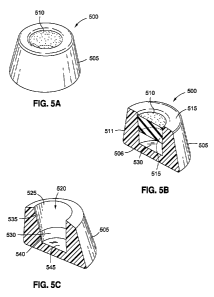
[079] FIG. 5A illustrates a staked-septum injection port 500.
For clarity, a stem or a tubing-insertion access is not shown.
In one embodiment, the injection port 500 may be injection port
415 of FIG. 4. The injection port 500 may include a housing 505
and an inserted septum 510.
[080] FIG. 5B illustrates a cross-sectional view of the
injection port 500 of FIG. 5A.
In this view, a structure of a
retaining lip 515 is visible and shown to overhang the outside
or needle-injection surface of the injection port 500.
The
retaining lip 515 may serve to prevent the septum 510 from
moving out of the housing 505. The geometry of the housing 505
further prevents the septum 510 from moving deeper into the
housing 505, when the septum 510 is pressed into position. For
example, a diameter 511 of the bottom surface of the septum 510
may be greater than a diameter 506 of the bottom cavity 530 of
the housing 505. In other words, since the diameter 511 of the
septum 510 is greater than a diameter of the bottom cavity 530,
the septum 510 is prevented from further movement into the
bottom cavity 530.
In this manner, the septum 510 may be
securely held in place or position after being pressed into the
housing 505.
[081] In one embodiment, when the septum 510 is held in
position within the housing 505, the retaining lip 515 and/or
the tight fit of the septum 510 within the housing 505 may cause
axial and/or radial compression, thereby enhancing a self-
sealing feature of the septum 510 in addition to holding the
septum 510 in place.
[082] FIG. 5C illustrates the housing 505 without the septum
510 for further clarity of the structural components of the
CA 056152 2014-042
WO 2013/059419 PCT/US2012/060760
housing 505.
As shown, the housing 505 may include a cavity
520, which may be divided into two portions, a top cavity 525
and a bottom cavity 530. The top cavity 525 may be defined by a
side inner wall 535 spanning circumferentially about an interior
portion of the housing 505.
The side inner wall 535 may also
taper inwards moving away from an opening of the cavity 520.
The top cavity 525 may be configured to have a similar shape
and/or dimensions as the septum 510 in order to house the septum
510.
The bottom cavity 530 may be defined by a second inner
side wall 540 and a bottom surface 545 of the housing 505. The
bottom cavity 530 may be intended to act as a fluid reservoir
for carrying fluid injected by a needle to the inflatable
portion of a gastric band and/or for carrying fluid from the
inflatable portion of the gastric band to the needle.
[083] FIG. 5D and FIG. 5E illustrate a perspective, cross-
sectional view and a cross-sectional view, respectively, of a
septum insertion and sealing process of the injection port 500.
As shown, a horn 550, which acts as an insertion and sealing
tool, may be initially positioned above the septum 510.
The
horn 550 may include a lip mold 555 located on a surface of the
horn 550 adjacent to the portion of the horn 550 attached to the
septum 510.
The lip mold 555 may surround an outer
circumference of the septum 510.
As shown, the horn 550 may
direct and position the septum 510 to be pressed into the top
cavity 525.
[084] FIG. 5F and FIG. 5G further illustrate a perspective,
cross-sectional view and a cross-sectional view, respectively,
of a pressing step of the septum insertion and sealing process
of the injection port 500. Here, the horn 550 is being pressed
downward to move the septum 510 into the top cavity 525 of the
housing 505.
In this position, the first inner side wall 535
may be in contact with the septum 510 and may exert radial
compression on the septum 510.
As the septum 510 moves lower
16
CA 056152 2014-042
WO 2013/059419 PCT/US2012/060760
into the housing 510, radial forces may be increased due to the
tapering of the inner side wall 535, thereby increasing
compression on the septum 510.
[085] FIGS. 5H and 51 illustrate a perspective, cross-sectional
view and a cross-sectional view, respectively, of the septum 510
being pressed further into the housing 505.
As shown, a
retaining edge 570, located at the top of the housing 505, may
protrude into the lip mold 555. In its current state (as shown
in FIG. 51), the retaining edge 570 cannot effectively prevent
the septum 510 from exiting the top of the cavity 520. However,
the retaining edge 570 does allow the septum 510 to enter (or be
pressed) into the cavity 520.
Once the septum 510 is pressed
into the cavity 520, the retaining edge 570 of the housing 505
may be melted as the horn 550 may supply heat, or heat may be
introduced to the retaining edge 570. To facilitate the melting
of the retaining edge 570, a plastic, polymer, or other material
having a melting point below the melting points of the material
of the septum 510 and the material of the horn 550 may be used.
In this manner, the retaining edge 570 may be melted and molded
into the lip mold 555 while retaining the integrity of the lip
mold 555 and the septum 510. As a result, the retaining edge
570 is transformed into a different physical shape, thereby
holding the septum 510 in place inside the cavity 520.
[086] FIG. 5J and FIG. 5K illustrate a perspective, cross-
sectional view and a cross-sectional view, respectively, of the
retaining edge 570 having been transformed into the retaining
lip 515 having an overhang portion which extends to contact and
hold the septum 510 in place, thereby preventing the septum 510
from exiting the cavity 530 of the housing 505. The retaining
lip 515 may also function to provide an axial load on the septum
510, which may cause an increase in radial compression exerted
by the inner side wall 535.
17
CA 056152 2014-042
WO 2013/059419 PCT/US2012/060760
[087] FIG. 5L and FIG. 5M illustrate a perspective, cross-
sectional view and a cross-sectional view, respectively, of the
manufactured injection port 500 with the horn 550 removed after
the retaining lip 515 has cooled and hardened. In this manner,
the injection port 500 may provide certain advantages over the
prior art, such as reduced parts (the resulting injection port
500 has two distinct parts), simple molding of parts, and/or a
simplified process for manufacturing a port/septum assembly.
[088] FIG. 6 is a flow chart 600 of the manufacturing process
for the injection port 500 of FIG. 5A. At step 605, the housing
505 for the injection port 500 may be molded. At step 610, the
septum 510 may be molded. At step 615, the septum 510 may be
pressed into the housing 505 by using the horn 550, and the
retaining edge 570 of the housing 505 may be melted and molded
into the lip mold 550 of the horn 550 resulting in the retaining
lip 515. At step 620, after the retaining lip 515 hardens, the
horn 550 may be removed, leaving the injection port 500.
The
assembly portion (e.g., step 615) comprises only one step, and
accordingly, this approach may be considered a "one step
process".
Advantageously, by simplifying the process to
manufacture an injection port, cost-savings and increased
uniformity may be achieved.
[089] FIG. 7A illustrates a septum-pressed injection port 700.
Shown assembled, the injection port 700 may comprise two
components: a housing 705 having septum-mating features and a
septum 710 having conical retention features.
The housing 705
may be plastic-molded and/or utilize any other moldable
materials suitable for implantation into the human body.
The
septum 710 may be silicone-molded and/or may utilize any other
moldable materials penetrable by a needle. The housing 705 and
the septum 710 may be of geometric and appropriate tolerance
design such that the septum 710 may be manually loaded into the
housing 705 while simultaneously maintaining effective radial
18
CA 056152 2014-042
WO 2013/059419 PCT/US2012/060760
and axial compression.
Also shown is a stem or a tubing-
insertion access 755. In one embodiment, the injection port 700
may be the injection port 415 of FIG. 4.
[090] FIG. 7B illustrates the septum 710 removed from the
housing 705 to more clearly illustrate the geometry of the
septum 710.
As shown here, the septum 710 may have conical
features including a retention ring 715 designed to hold the
septum 710 within the housing 705, a needle-injection surface
720 designed to be penetrable by a needle, and a sealing surface
725 positioned between the needle-injection surface 720 and the
retention ring 715 designed to further seal in fluid held within
the housing 705 by the septum 710.
[091] FIG. 7C is a cross-sectional view of the housing 705
without the septum 710 (the septum 710 being omitted in this
FIG. for clarity of the features of the housing 705).
The
housing 705 may include a large cavity 730, being further
divided into a top cavity 733 for holding the septum 710 and a
bottom cavity 745 for carrying fluid (as the fluid reservoir).
The top cavity 733 may be defined by a tapered side wall 750
positioned between a retention lip 735 and a retention
protrusion 740.
The retention lip 735 may be designed to
overhang the retention ring 715 of the septum 710 when the
septum 710 is correctly positioned within the top cavity 733.
The retention protrusion 740 may be designed to protrude from
the tapered side wall 750 defining a bottom retaining surface
for contacting a bottom surface of the septum 710 and preventing
the contacted portions of the bottom surface of the septum from
extending beyond the retention protrusion when the retention lip
735 is overhanging and contacting the retention ring 715 of the
septum 710, thereby preventing the septum 710 from moving into
the bottom cavity 745. The bottom cavity 745 may be defined by
a bottom side wall 760 which may have a channel or fluid conduit
leading to the tubing-insertion access 755. As the housing 705
19
CA 056152 2014-042
WO 2013/059419 PCT/US2012/060760
may be constructed out of a mold, one or more of the structural
features of the housing 705 may be integrated into the physical
structure of the housing 705.
[092] FIG. 7D is a cross-sectional view of the septum 710
within the housing 705 and further clarifies how the features of
the septum 710 mate with the features of the housing 705 to
secure the septum 710 within the housing 705.
As shown, the
retention lip 735 overhangs and contacts a portion of the
retention ring 715 of the septum 710 to prevent the septum 710
from exiting the cavity 733 of the housing 705 when the septum
710 is positioned within the cavity 733.
The retention
protrusion 740 may contact a bottom surface 726 of the septum
710 to prevent the septum 710 from moving into the bottom cavity
745, leaving the bottom cavity 745 free to carry fluid to and
from the inflatable portion of the gastric band through the
tubing-insertion access 755.
In addition, when the septum 710
is held between the retention lip 735 and the retention
protrusion 740, the septum 710 is radially compressed (by the
tapered walls) and axially compressed (by the retention lip 735
and the retention protrusion 740), thereby enhancing the self-
sealing features of the septum 710.
[093] FIG. 8 illustrates an alternative embodiment of the
pressed-septum injection port 700.
In essence, the tubing-
insertion access 755 is replaced by a tubing connector 855
molded and/or integrated into a housing 805 of the injection
port 800.
All other components of the injection port 800
including a septum 800 correspond with features discussed above
in conjunction with the injection port 700.
[094] The embodiments of FIGS. 7A-7D and FIG. 8 provide reduced
cost by eliminating all but two components needed for an
injection port, namely the housing and the septum while further
reducing assembly costs during production by making it a one
step process.
Furthermore, assembly may be performed with
CA 056152 2014-042
WO 2013/059419 PCT/US2012/060760
manual operation or with a simple tool, thereby further reducing
the need to design or utilize expensive machinery for assembly.
[095] FIG. 9 is a flow chart 900 of the manufacturing process
for the injection port 700 of FIG. 7A and/or the injection port
800 of FIG. 8A. As shown, the manufacturing process 900 begins
at step 905 with the molding of the septum into the shape
illustrated in FIG. 7B. Next, at step 910, the housing is
molded into the shape as shown in FIG. 7C. At step 915, once
the septum and the housing are molded, the septum is pressed
into the housing until the retention ring is engaged by the
retention lip and the septum is held in place as shown in FIGS.
7A and 7D.
[096] FIG. 10A illustrates another embodiment of an injection
port, and more particularly, showing a drum-shaped injection
port 1000.
The drum-shaped injection port 1000 may, in one
embodiment, be shaped substantially similar to a hemisphere
where the septum is located on the flat side, and not on the
curved side.
The drum-shaped injection port 1000 may provide
the benefits of reduced production costs and improved
reliability while maintaining the efficacy level common to
current injection ports.
The drum-shaped injection port 1000
may be assembled manually or with only a simple tool (e.g., to
apply heat).
[097] As further illustrated in the exploded view of the drum-
shaped injection port 1000 of FIG. 10B and the cross-sectional
view of FIG. 10C, the drum-shaped injection port 1000 may
include a housing 1005 having a retaining ring 1020 (e.g.,
shaped as a circle or oval) defining an opening at the top of
the housing 1005.
The retaining ring 1020 may be integrated
with a dome-shaped base which is configured to define a cavity
or reservoir 1030 that holds the fluid.
The drum-shaped
injection port 1000 may also include a septum 1010 shaped to fit
the opening of the retaining ring 1020 such that a top surface
21
CA 056152 2014-042
WO 2013/059419 PCT/US2012/060760
1035 of the septum 1010 is flush with a top edge 1040 of the
retaining ring 1020.
The septum 1010 may be a biocompatible
rubber or other biocompatible materials having self-sealing
capabilities or properties having a diameter between about 1
centimeters (cm) and 8 centimeters (cm), but preferably between
about 1 cm - about 5 cm. The retaining ring 1020 may define a
first portion of a cavity having a diameter substantially equal
to the diameter of the septum 1010.
The first portion of the
cavity may lead into a second portion of the cavity having an
incrementally decreasing diameter moving away from the retaining
ring 1020 in order to produce the drum or hemispherical shape of
the injection port 1000 and span the top surface 1035 of the
septum 1010.
[098] In addition, the injection port 1000 may include a
covering seal 1015 configured to fit the exterior of the
retaining ring 1020. The covering seal 1015 may have a mesh or
some other type of needle penetrable material to cover the
septum 1010 and to assist the holding of the septum 1010 in
place, and to help maintain septum integrity during internalized
increased port pressure.
[099] While not shown, a tubing connector could be molded into
the drum-shaped injection port 1000 via side access or
integrated into a reservoir defining wall 1025 of the housing
1005. By integrating the tubing connector into the mold, this
concept has the flexibility of incorporating the tubing
connection anywhere along the housing 1005.
[0100] FIG. 11 is a flow chart 1100 detailing one embodiment of
to the manufacturing process of the drum-shaped injection port
1000 of FIGS. 10A-10C. At step 1105, the housing 1005 is molded
out of biocompatible material such as a plastic or metal into
the cup or drum shape with a low profile. Next, at step 1100,
the septum 1010 may be molded out of a rubber to be in the shape
of a disc and having a diameter to fit tightly into the
22
CA 056152 2014-042
WO 2013/059419 PCT/US2012/060760
retaining ring 1020 of the housing 1005. At step 1115, the
covering seal 1015 may be molded out of a biocompatible plastic
(e.g., a plastic with a lowering melting point than that of both
the housing 1005 and the rubber septum 1010, and configured to
fit about the exterior of the retaining ring 1020.
Alternatively, the covering seal 1015 may be stamped, extruded,
cut, woven, or braided, among other techniques.
[0101] Once the parts are constructed, then at step 1120, the
septum 1010 may be inserted into the housing 1005 undergoing
radial compression caused by interference with the retaining
ring 1020. The septum 1010 should fit within the retaining ring
1020 in a flush manner and may be prevented from protruding into
the cavity 1030 by the shape of the reservoir-defining wall
1025. In other words, because the reservoir-defining wall 1025
is shaped as a dome and gradually decreases in diameter as it
moves away from the retaining ring 1020, the diameter of the
septum 1010 causes it to be held in place.
At step 1125, the
covering seal 1015 may be pulled over the septum 1010 thereby
forming a seal. The covering seal 1015 may be form fit over the
exterior of the retaining ring 1020 as well, and in this manner,
capping the drum-shaped injection port 1000. At step 1130, the
covering seal 1015 may be thermally sealed circumferentially
about the exterior of the retaining ring 1020 by utilizing a
heating device to prevent leaks and to hold the septum 1010 in
place.
Alternatively, the covering seal 1015 may be crimpled,
bonded or mechanically fixed to the housing 1005.
[0102] In one embodiment, the septum 1010 and the covering seal
1015 may be orientation-independent thereby further simplifying
the manufacturing process.
Furthermore, the resulting drum-
shaped injection port 1000 has a low-profile which may be
aesthetically acceptable to the patient while still providing a
large surface area for needle penetration.
23
CA 056152 2014-042
WO 2013/059419 PCT/US2012/060760
[0103] In one embodiment, the covering seal 1015 may be mesh-
patterned to increase longevity and maintain integrity even
after multiple needle injections.
[0104] FIG. 12A illustrates a mold-in septum port 1200. Here, in
this embodiment, a septum 1255 having self-sealing
characteristics and properties may be molded into an already
existing housing 1205, resulting in the mold-in septum port
1200.
[0105] Structurally, the housing 1205 may include a large cavity
1215, being further divided into a top cavity 1220 for holding
the septum 1255(shown in FIG. 12D) and a bottom cavity 1225 for
carrying fluid (as the fluid reservoir).
The top cavity 1220
may be defined by a top side wall 1230 positioned between a
retention lip 1235 and a retention protrusion 1240.
The
retention lip 1235 may be designed to extend over the surface of
the septum 1255 to prevent the septum 1255 from exiting out of
the top of the mold-in septum port 1200 when the septum 1255 is
correction positioned within the top cavity 1220. The retention
protrusion 1240 may be designed to protrude from the top side
wall 1230 and contact a bottom surface of the septum 1255,
thereby preventing the septum from moving into the bottom cavity
1225.
The bottom cavity 1225 may be defined by a bottom side
wall 1245 which may have a channel or fluid conduit leading to a
tubing-insertion access 1210.
As the housing 1205 may be
constructed out of a mold, all of the structural features of the
housing 1205 may be integrated into the physical structure of
the housing 1205.
[0106] The physical structure of the housing 1205 of the mold-in
septum port 1200 having been described, attention will now be
turned to the manufacturing of the mold-in septum port 1200 with
respect to FIGS. 12B-D and FIG. 13.
[0107] As depicted in the flowchart of FIG. 13, at step 1305,
the housing 1205 is molded, resulting in the "blank" housing
24
CA 056152 2014-042
WO 2013/059419 PCT/US2012/060760
1205 of FIG. 12B. Once the housing 1205 is formed, the rest of
the mold-in septum port 1200 may be assembled.
At step 1310,
and as shown in FIG. 12C, a temporary support filling 1270 such
as an incompressible fluid, inflatable bladder and the like may
be placed in the bottom cavity 1225 to prevent the later added
silicone septum 1255 from sinking into the bottom cavity 1225.
If desired, at step 1315, an interface layer 1275 designed to be
needle-penetrable may be inserted on top of the temporary
support material.
After the temporary support filling 1270 is
inserted to fill the bottom cavity 1225 of the housing 1205, the
septum 1255 may now be inserted. At step 1320, the housing 1205
with the temporary support filling 1270 is placed in a molding
machine and heated and/or stretched out to increase the inner
diameters of the housing 1205. Next, at step 1325, the septum
1255 is inserted via the diameter-expanded opening of the
housing 1205 and molded under compression.
Then at step 1330,
the heating or stretching of the housing 1205 is removed,
thereby returning the housing to its original shape (with a
smaller diameter of the openings, etc.) to fix the septum 1255
in place and further, to provide the septum 1255 with radial and
axial compression to enhance the self-sealing capabilities of
the septum 1255. The result of step 1330 is illustrated by FIG.
12D.
[0108] At step 1335, the temporary support filling 1270 may be
removed (e.g., through the tubing connector 1210) to result in
the assembled mold-in septum port 1200 as depicted in FIG. 12A.
[0109] As an alternative, an over-molded port 1400 as depicted
in FIGS. 14A and 14B may provide for a completely sealed port
encapsulated in solid material.
Generally, a septum 1405, a
compression ring 1410 defining a reservoir 1415 and a stem
insert or tube connector 1420, as shown in FIG. 14C may be
assembled in a top mold 1425 and the bottom mold 1426 of FIG.
14D to result in the assembly 1450 of FIG. 14E. The septum 1405
CA 056152 2014-042
WO 2013/059419 PCT/US2012/060760
may include a top surface, a bottom surface and a side wall for
joining the top surface and the bottom surface. The compression
ring 1410 may receive the septum 1405 and further define a
reservoir 1415 and may include a ring portion 1416 for holding
the septum 1405 in place, and a reservoir defining portion 1417
integrated with the ring portion 1416, the reservoir defining
portion 1417 having a stem insert or connector interface 1418
(e.g., a hole or a port).
[0110] Referring back to FIG. 14D, the mold 1450 may allow for
the injection of the biocompatible material (e.g., titanium) to
form the housing and encapsulate a portion of the septum 1405,
the compression ring 1410 and the stem insert 1420.
The top
mold 1425 may include a void or spacing designed to be filled by
an injected biocompatible material such as titanium to form the
housing of the over-molded port 1400. The bottom mold 1426 may
include a stem holder 1435 designed to hold the stem insert or
tube connector 1420. In one embodiment, the spacing in the top
mold 1425 and the bottom mold 1426 to formulate the housing may
provide radial compression to the septum 1405 once the
biocompatible material to be used as the housing is injected
into and/or molded over the septum 1405, the compression ring
1410 and the stem insert or tube connector 1420.
Furthermore,
in one or more embodiments, intentional voids can be left in the
over-molded plastic to reduce the use of implantable materials
to save on costs.
These voids could be filled, left open or
designed with features to promote tissue in-growth at the base
of the over-molded port 1400.
[0111] Referring back to the compression ring 1410, in one
embodiment, a high durometer (shore A durometer of 70 or
greater) material may be used to construct the compression ring
1410.
[0112] FIG. 15 illustrates one example of a cross-sectional view
of a stretched-on compression assembly 1500, which in one
26
CA 056152 2014-042
WO 2013/059419 PCT/US2012/060760
embodiment, may be utilized as the compression ring 1410 of the
over-molded port 1400 of FIG. 14A.
Here, the compression ring
1505 may surround a previously-cured septum 1510 by being
stretched around or compression-molded onto the outside of the
septum 1510 to create the stand-alone radially compressed
septum.
[0113] FIG. 16 illustrates an alternative compression ring
assembly 1600 which may be incorporated as the compression ring
1410 of the over-molded port 1400 of FIG. 14A.
More
particularly, as shown in FIG. 16, a ring structure 1605
constructed out of a memory material (e.g., a nitinol
compression coil) may be utilized as the compression ring and
molded into the silicone rubber septum 1610. Compression may be
effected by heating the memory material to return the memory
material to its memory state thereby radially compressing the
silicone rubber septum 1610.
[0114] A variation of the over-molded port 1400 of FIG. 14A
which does not require a compression ring is illustrated in FIG.
17.
While the resulting over-molded port 1700 may appear
similar to the over-molded port 1400 of FIG. 14A, the top and
bottom molds 1725, 1726 and certain component parts (the
reservoir 1710) are modified. For example, the compression ring
portion of the analogous component (compression ring and
reservoir 1410) has been removed, resulting in only the
"reservoir 1710".
The reservoir 1710 may include septum
supporting structures 1730 to suspend a septum 1705 in place
above the reservoir 1710.
In this embodiment, the pressure of
the injected material to form the housing may provide radial
compression on the septum 1705.
[0115] The concept of using the injection process to provide
compression may be modified and applied to other injection
ports. For example, FIG. 18A illustrates an injection port 1800
having a septum 1805 inserted into a housing 1810. Compression
27
CA 056152 2014-042
WO 2013/059419 PCT/US2012/060760
on the septum 1805 may be provided by injecting a compression
providing substance, for example, liquid silicone injections
1815 under pressure after the septum 1805 is already inserted
into the housing 1810 without the desired amount of compression.
In this particular embodiment, vents 1820 may be left to seal
the injection port 1800.
This type of construction of the
injection port 1800 may be considered a post-injected silicone
compressed septum assembly.
[0116] FIG. 18B illustrates injection nozzles 1825 which may be
used to provide the liquid silicone injections into a gap 1816.
In this manner, the septum 1805 may be radially compressed. The
compression of the septum 1805 improves the sealing of the
injection port 1800 and also provides the benefit of improving
the self-sealing characteristics of the septum 1805 after the
septum 1805 is punctured with a needle.
[0117] In one embodiment, manufacturing the injection port 1800
may comprise molding a housing 1810 to include an opening at a
top of the housing 1810 leading into a cavity defined by an
inner side wall 1817 of the housing 1810 and an inner bottom
wall of the housing 1810, the cavity having a first portion and
a second portion, the first portion of the cavity being
positioned between the opening and the second portion of the
cavity.
Next, a septum 1805 may be inserted into the first
portion of the cavity leaving a gap 1815 between an exterior of
the septum 1805 and the inner side wall.
Then, radial
compression exerted on the septum 1805 may be increased by
adding liquid silicone or other appropriate substances to fill
the gap 1815 between the exterior of the septum 1805 and the
inner side wall of the housing 1810 via injection.
That is,
liquid silicone may be injected into the gap 1815 using
injection nozzles inserted into openings that extends from the
side of the housing 1810 into the gap 1815.
28
CA 056152 2014-042
WO 2013/059419 PCT/US2012/060760
[0118] FIG. 19A illustrates a dome-shaped port 1900 which may
be, in one embodiment, include a compressed septum (e.g., formed
from a silicone from a membrane) located in a housing to form a
hemispherically-shaped object.
The dome-shaped port 1900 may
advantageously incorporate the compressive effect that bending
has on materials to create a compressed silicone septum 1905
located in a housing 1910.
To construct the dome-shaped port
1900, a flat piece of silicone-sheeting 1901 (as shown in FIG.
19B) with woven mesh adhered to one side may be used.
The
silicone-sheeting 1901 may originally be a disc, and may be
integrated with a mesh 1902. As the silicone-sheeting 1901 is
forced into a dome shape, the silicone-sheeting 1901 may be
structurally held in the dome shape with the mesh 1902 on the
outside to maintain the compression to seal against needle
punctures as shown in FIG. 19C.
[0119] Structurally, the housing 1910 may include
a
substantially circular cut-out portion defined by a
circumferential edge 1906 (for exposing the septum to a needle),
a bottom surface having 1908 a diameter larger than the
circumferential edge 1906, and a curved side wall 1907 extending
from the circumferential edge 1907 to the bottom surface 1908.
[0120] In one embodiment, barbs (not shown) may be designed in
the mesh 1902 to hold it in place when the injection port 1900
is under pressure.
[0121] As an alternative, the silicone-sheeting 1901 may be
molded into an inverted dome. When the inverted dome is flipped
and assembled into the housing 1910, the compression may be
doubled to that of the flat-disc formed into the dome shape.
[0122] Various port assemblies now having been described,
attention will be turned to certain features which may be added
to any port assembly, whether described herein or not, to
further improve the performance of the port assembly.
29
CA 056152 2014-042
WO 2013/059419 PCT/US2012/060760
[0123] In one embodiment, a lip seal may be incorporated into a
septum to improve reservoir sealing under pressure.
The lip
seal may still allow for improved needle puncture sealing. For
example, FIG. 20 illustrates an injection port 2000 having a lip
seal 2005 integrated into the septum 2010.
When the lip seal
2005 is pressed against a reservoir wall 2015 as the fluid
increases in a cavity 2020 (e.g., in response to pressure
increase caused by the added fluid), the sealing capacity or
ability of the lip seal 2005 also increases, thereby preventing
leaks around the septum 2010.
[0124] In addition to lip seals, a softer tubing connection may
be incorporated to prevent premature wearing of the connected
tubing to an injection port and reduce or eliminate the need for
titanium stems or bulky strain reliefs to protect the tubing.
Softer tubing connections may avoid the use of harder materials
and protruding stems (although the user of harder materials is
still possible if needed).
[0125] Typically, a stem may be load-concentrated at an
unprotected and minimally supported portion. For example, FIG.
21 illustrates a tubing connector 2100 load concentrated at
arrow 2105.
By having the load concentrated as such a point,
the connector failure rate is adversely increased. Indeed, this
is the source of most connector failures.
[0126] By sinking the tubing connector as shown in FIGS. 22 and
23, the load may be diverted from the tip of the connector.
[0127] FIG. 22 illustrates a sunken connector 2200 having an
exit that is radiused at location 2210 to further prevent a
concentrated load on the sunken connector 2200.
The connector
2200 is "sunken" into or partially inserted into the access port
housing itself.
In other words, a first portion of the sunken
connector 2200 is located inside the access port housing while a
second portion of the sunken connector 2200 is located outside
of the access port housing and leading to the tubing.
By
CA 056152 2014-042
WO 2013/059419 PCT/US2012/060760
configuring the connector 2200 to be insertable into the
housing, the load is diverted away from the tip of the connector
2200 and supported by not only the tip of the connector 2200 but
also by the portion of the access port housing surrounding the
top of the connector 2200.
[0128] Alternatively, and/or in addition, a sunken connector
2300 may be utilized with a strain relief mechanism 2305.
Similar to connector 2200, connector 2300 is insertable into the
access port housing itself.
Here, the strain relief mechanism
2305 may appear as wings or protrusions that partially or fully
fill the opening of the access port to provide strain relief.
[0129] The port connector may further be enhanced to provide
additional benefits to the patient.
For example, a tubing
connector 2400 of FIG. 24 may include in-growth features 2405 to
create proper fixation of an injection port to a patient's
tissues.
Such in-growth features 2405 may be added to the
tubing connector 2400 or tubing as a means of attachment rather
than sutures, anchors or mesh.
These in-growth features 2405
may come in many forms such as pores, hole-filled, or other
configurations to encourage integration into the patient's
bodily tissues.
In this particular embodiment, the in-growth
features 2405 may be two sets of four integrated holes on either
side of the tubing connector 2400. However, the actual number
and/or configuration of the holes may be altered as desired.
[0130] Unless otherwise indicated, all numbers expressing
quantities of ingredients, volumes of fluids, and so forth as
used in the specification and claims are to be understood as
being modified in all instances by the term "about."
Accordingly, unless indicated to the contrary, the numerical
parameters set forth in the specification and attached claims
are approximations that may vary depending upon the desired
properties sought to be obtained by the present invention. At
the very least, and not as an attempt to limit the application
31
CA 056152 2014-042
WO 2013/059419 PCT/US2012/060760
of the doctrine of equivalents to the scope of the claims, each
numerical parameter should at least be construed in light of the
number of reported significant digits and by applying ordinary
rounding techniques. Notwithstanding that the numerical ranges
and parameters setting forth the broad scope of the invention
are approximations, the numerical values set forth in the
specific examples are reported as precisely as possible.
Any
numerical value, however, inherently contains certain errors
necessarily resulting from the standard deviation found in their
respective testing measurements.
[0131] The terms "a," "an," "the" and similar referents used in
the context of describing the invention (especially in the
context of the following claims) are to be construed to cover
both the singular and the plural, unless otherwise indicated
herein or clearly contradicted by context. Recitation of ranges
of values herein is merely intended to serve as a shorthand
method of referring individually to each separate value falling
within the range.
Unless otherwise indicated herein, each
individual value is incorporated into the specification as if it
were individually recited herein. All methods described herein
can be performed in any suitable order unless otherwise
indicated herein or otherwise clearly contradicted by context.
The use of any and all examples, or exemplary language (e.g.,
"such as") provided herein is intended merely to better
illuminate the invention and does not pose a limitation on the
scope of the invention otherwise claimed. No language in the
specification should be construed as indicating any non-claimed
element essential to the practice of the invention.
[0132] Groupings of alternative elements or embodiments of the
invention disclosed herein are not to be construed as
limitations. Each group member may be referred to and claimed
individually or in any combination with other members of the
group or other elements found herein.
It is anticipated that
32
CA 056152 2014-042
WO 2013/059419 PCT/US2012/060760
one or more members of a group may be included in, or deleted
from, a group for reasons of convenience and/or patentability.
When any such inclusion or deletion occurs, the specification is
deemed to contain the group as modified thus fulfilling the
written description of all Markush groups used in the appended
claims.
[0133] Certain embodiments of this invention are described
herein, including the best mode known to the inventors for
carrying out the invention.
Of course, variations on these
described embodiments will become apparent to those of ordinary
skill in the art upon reading the foregoing description.
The
inventor expects skilled artisans to employ such variations as
appropriate, and the inventors intend for the invention to be
practiced otherwise than specifically described herein.
Accordingly, this invention includes all modifications and
equivalents of the subject matter recited in the claims appended
hereto as permitted by applicable law.
Moreover, any
combination of the above-described elements in all possible
variations thereof is encompassed by the invention unless
otherwise indicated herein or otherwise clearly contradicted by
context.
[0134] Furthermore, certain references have been made to patents
and printed publications throughout this specification. Each of
the above-cited references and printed publications are
individually incorporated herein by reference in their entirety.
[0135] Specific embodiments disclosed herein may be further
limited in the claims using consisting of or and consisting
essentially of language.
When used in the claims, whether as
filed or added per amendment, the transition term "consisting
of" excludes any element, step, or ingredient not specified in
the claims.
The transition term "consisting essentially of"
limits the scope of a claim to the specified materials or steps
and those that do not materially affect the basic and novel
33
CA 02856152 2014-04-22
WO 2013/059419 PCT/US2012/060760
characteristic(s). Embodiments of the invention so claimed are
inherently or expressly described and enabled herein.
[0136] In closing, it is to be understood that the embodiments
of the invention disclosed herein are illustrative of the
principles of the present invention.
Other modifications that
may be employed are within the scope of the invention. Thus, by
way of example, but not of limitation, alternative
configurations of the present invention may be utilized in
accordance with the teachings herein. Accordingly, the present
invention is not limited to that precisely as shown and
described.
34