Note: Descriptions are shown in the official language in which they were submitted.
CA 02856242 2014-05-16
WO 2013/079891 PCT/GB2011/052340
1
VALVE ACTUATOR TORQUE LIMITER
The present invention relates to torque limiters.
The force applied to a motor-driven actuating mechanism, such as a
valve actuator, is often controlled by a torque sensing device, in which
torque
reaction in the actuating mechanism is utilised to disconnect the power to the
driving motor once a preset value of torque is reached. A typical motor-driven
actuating mechanism may have a worm and wheel, with the wormshaft able to
move in an axial direction against springs, the deflection of the shaft being
a
measure of the torque appliedto the wormwheel and actuator output. The
resulting deflection may be utilised to switch off an electric motor by means
of a
torque limit switch and contactor, or disconnect a fluid-powered motor through
a
suitable valve system. An example of this type of torque limiter is given in
GB1446005.
Conventionally, the torque limiter is located on the end of the motor
because that is where the worm shaft can be accessed and adapted. However,
in some cases, such as valve actuators where a separable motor is employed,
the torque limiter cannot be positioned there because there is no access to
the
motor shaft at the enclosed end of the motor housing. This requires the
limiter
to be moved inboard and so adjusting it is not easily achievable.
Embodiments of the present invention are intended to address at least
some of the issues discussed above.
According to a first aspect of the present invention there is provided a
valve actuator torque limiter, the torque limiter including or comprising:
CA 02856242 2014-05-16
WO 2013/079891 PCT/GB2011/052340
2
a moveable shaft moveable two ways in an axial direction and, in use,
rotatable to cause rotation of a valve actuator drive shaft;
a brake disc mounted on the moveable shaft;
a first friction device located to a first side of the brake disc;
a second friction device located to a second side of the brake disc;
where, in use, contact between the brake disc and the first or the second
friction device stops a motor rotating the moveable shaft;
a casing housing at least the brake disc, the first friction device and the
second friction device, and
an adjusting arrangement for adjusting a position of the first friction device
and/or the second friction device relative to the brake disc, wherein the
adjusting
arrangement is operable from outside the casing.
The first and/or the second friction device may comprise a friction disc
having a gear. The adjusting arrangement may include a worm drive gear
associated with the gear of the first and/or the second friction disc. The
worm
drive gear may comprise an elongate member having a threaded portion that, in
use, engages its associated gear. A portion of the worm drive gear may
protrude through an aperture in the casing. The protruding portion can include
a
slot or the like to assist with adjustment using a tool, such as a
screwdriver. A
locking device may be provided adjacent an external end of the worm drive
gear.
In some embodiments, there are two worm drive gears, one associated with the
first friction disc and another associated with the second friction disc.
The adjustment arrangement may be accessible through the casing, in
use, at a location between the motor and the drive shaft.
CA 02856242 2014-05-16
WO 2013/079891 PCT/GB2011/052340
3
The moveable shaft may comprise a worm shaft that, in use, engages
with a worm gear on the drive shaft.
The casing may at least partially house the moveable shaft. The casing
may include: a first casing component for, in use, housing a motor; a second
casing component for housing parts of the torque limiter; a third casing
component for housing parts of the torque limiter and, in use, the drive
shaft.
According to another aspect of the invention there is provided a valve
actuator including or comprising:
a drive shaft for opening/closing a valve;
a motor for rotating the drive shaft, and
a torque limiter substantially as described herein.
The casing may at least partially house components of the valve actuator
as well as components of the torque limiter.
According to yet another aspect of the invention there is provided a valve
assembly including a valve and a valve actuator substantially as described
herein. , The valve assembly may include a second stage gearbox.
The invention extends to any feature, or any combination of features
described herein, whether or not that combination is explicitly described
herein.
The invention can be put into effect in numerous ways, one example only
being described and illustrated with reference to the drawings, wherein:
Figure 1 shows an external view of part of a valve actuator including a
torque limiter;
Figure 2 shows a drive shaft of the valve actuator and components of the
torque limiter, and
CA 02856242 2014-05-16
WO 2013/079891 PCT/GB2011/052340
4
Figure 3 is a sectional view through components of the torque limiter.
Referring to Figure 1, parts of a valve actuator, generally shown at 100,
are illustrated. The valve actuator can be any suitable device, such as the
actuators available from Rotork PLC, of Bath, United Kingdom, and will
typically
include a handwheel 104 that can be used to manually adjust the position of
the
drive shaft 203 instead of the motor. The valve actuator includes casing 102,
which in the example is formed of several components (but in alternative
versions could be one piece) fitted together by any suitable means, e.g.
nuts/bolts, welding, etc. These include: casing component 102A for housing a
motor (not visible in Figure 1); casing component 102B for housing parts of a
torque limiter (shown generally at 103), and casing component 102C for housing
parts of the torque limiter and the drive shaft of the actuator, which will be
described below. There is also a further piece of casing 102D that contains a
switching mechanism for the valve assembly. The design, dimensions and
material(s) used for the casing can vary, but will typically be formed of
robust
material, such as cast iron, aluminium or hardened steel. In the example
described herein, the torque limiter is integrally built into the body of the
actuator, but it will be understood that in alternative embodiments, it could
be a
separate module that is fitted to a pre-formed actuator, for example.
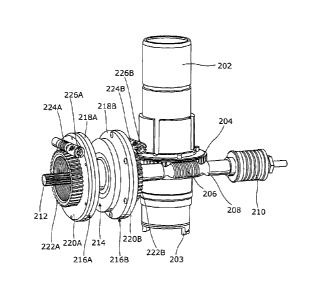
Figure 2 shows the drive shaft 202 of the valve actuator, which includes a
final drive 203, along with parts of the torque limiter. The shaft is fitted
with a
worm gear 204 that engages with a threaded section 206 of a worm shaft 208.
Thus, rotation of the worm shaft around a horizontal axis (in the Figure)
results
in rotation of the drive shaft around a vertical axis, with clockwise and anti-
CA 02856242 2014-05-16
WO 2013/079891 PCT/GB2011/052340
clockwise rotation of the drive shaft corresponding to closed and open
positions,
respectively, of the valve in the example. A second stage gearbox may also be
included in some versions of the assembly, between the actuator and the valve.
Fitted towards the right-hand of the worm shaft is a spring pack 210 that
allows
5
axial movement of the worm shaft in response to torque being generated
through the worm gear 204 to the drive shaft 202. Some components of the
torque limiter described herein, such as the spring pack 210, correspond to
those found in the AT, NATI , NAT5, NATI E, NAT5E actuator ranges available
from Rotork PLC.
Referring now to Figure 3 in addition to Figure 2, the left-hand end of the
worm shaft 208 is in communication with a motor 302 via a sliding coupling
212.
The motor includes a central shaft 303, one end of which includes a cavity 305
adapted for receiving the sliding coupling. The other end of the shaft is
passes
through a spring 307 to a bearing 309. The connection between the central
motor shaft 307 and the wormshaft 208 is a sliding coupling that allows the
wormshaft to move axially in relation to the fixed central motor shaft. A
brake
disc 214 is mounted on the worm shaft, generally at a position between the
drive
shaft 202 and the motor casing 102A. A first friction disc 216A is located to
the
left-hand side of the brake disc, and a second friction disc 216B is located
to the
right-hand side of the brake disc. Each friction disc has a high-friction
surface
218A, 218B (formed of a composite temperature stable rigid moulded friction
material) that can engage with the brake disc. Each high-friction surface is
fixed
onto a rigid disc 220A, 220B. Extending out of the face of each rigid disc
that is
CA 02856242 2017-02-06
6
not in contact with the associated high-friction surface is an outer gear
wheel
222A, 222B.
As best seen in Figure 3, the left-hand friction disc 216A is mounted
on a threaded cylindrical inner portion 225 of the casing component 102B,
allowing it to move axially within a generally ring-shaped cavity 227 within
the
casing component (when rotated by the adjustment worm 224B described
below). The right-hand disc 216B is mounted in a similar arrangement (not
shown) of the casing component 102C.
As best seen in Figure 2, each outer gear wheel 222A, 222B has an
associated worm drive gear 224A, 224B that is an elongate member having a
threaded portion that, in use, engages with its outer gear wheel. The length
of
each worm drive gear is such that a portion of it protrudes through an
aperture
in the casing 102, as shown in Figure 1. The other end of the worm drive gear
can be supported by a bearing inside the casing. The end of the protruding
portion can include a slot or the like to allow the worm gear to be rotatably
adjusted easily, e.g. using a tool, such as a screwdriver. It will be
appreciated
that other arrangements for adjusting the position of the friction discs 216A,
216B can be used, e.g. a ratchet-type mechanism. An indented locking device
226A, 226B may also be provided adjacent the external end of each worm drive
gear to give a positive location of the adjusting worms 224A, 224B.
In use, axial movement of the worm shaft 208, under the control of the
motor 302, and the brake disc 214 mounted upon can result in either contact
with the open direction friction disc 216A, or the closed direction friction
disc
216B, generating a braking effect. The axial displacement of the worm shaft is
CA 02856242 2014-05-16
WO 2013/079891 PCT/GB2011/052340
7
directly related to the torque delivered by the drive shaft 202 and so the
maximum torque delivered by the drive shaft can be adjusted externally by
means of the individual worm gear drive arrangements 224A, 224B (i.e. one for
open torque and one for the closed torque). Rotating the worm gear drive
arrangements will cause the associated friction disc 216A, 216B to rotate and
move axially via the outer gear wheels 222A, 222B, repositioning them in
relation to the brake disc 214. Using a suitable output torque measuring
system,
the torque limiter can be adjusted by worm gear drive arrangements 224A, 224B
to limit the maximum torque delivered under any operating conditions to
application specific values.
When the friction discs 216A, 216B are positioned closely to the brake
disc 214, only a small axial displacement is required to generate the braking
effect, thus limiting the torque available at the drive shaft 202 to a
minimum.
Conversely, the friction discs may be positioned further away from the brake
disc
so as to have no braking effect, thus enabling a wide range of adjustment of
maximum torque generated by the drive shaft of the actuator. The worm drive
gears can be of a gear ratio that is non-reversible and their locking devices
226A, 226B can help ensure creep in the position of the friction discs does
not
occur.
By having the adjustment devices located inboard of the motor, the torque
limiter described herein can provide benefits in terms of sizing, whereby
because the maximum torque capabilities of the actuator is guaranteed, the
stresses on the valve are reduced allowing valve designers to choose
appropriate materials. Thus, the torque limiter can result in reduced costs,
whilst
CA 02856242 2014-05-16
WO 2013/079891 PCT/GB2011/052340
8
still meeting or exceeding basic safety requirements. It will be appreciated
that
the torque limiter can be used with various types of valve actuators, as well
as
other types of motor-driven actuating mechanisms.