Note: Descriptions are shown in the official language in which they were submitted.
CA 02856549 2014-05-21
WO 2013/082581 PCT/US2012/067563
SURGICAL NAVIGATION FOR REPAIR OF HEART VALVE LEAFLETS
FIELD OF THE INVENTION
The present invention relates to minimally invasive repair of heart valve
leaflets. More
BACKGROUND OF THE INVENTION
Degenerative mitral valve disease (DMVD) is a common heart valve disorder in
which
Open heart cardiac surgery is highly invasive with a long recovery period, and
not well
tolerated by elderly or co-morbid patients. Recent innovations in minimally
invasive and robotic
Devices capable of performing off-pump, mitral valve repair for certain forms
of DMVD,
such as those disclosed in U.S. Patent Publication Nos. 2008/0188873,
2010/0174297,
2009/0105279 and 2009/0105751, have recently been developed. Such devices can
use trans-
apical access to approach and capture the prolapsed portion of the mitral
valve leaflet, attach a
1
CA 02856549 2014-05-21
WO 2013/082581 PCT/1JS2012/067563
guidance can be problematic as it may not always be possible to maintain
appropriate spatial and
temporal resolution in 3D, and it may not always be possible using single 2D
and 2D bi-plane
views to simultaneously maintain both the tool tip and target site in the
field of view. Using 2D
echo it also can be difficult to ensure that the tool tip, rather than a cross
section of the tool shaft,
is visualized. Due to these navigation challenges, the tool can become caught
in the region
below the valve leaflet, risking leaflet perforation.
After extensive animal studies, the devices described in the above-referenced
publications are currently undergoing preliminary in-human trials for the
repair of flailing mitral
valves. The procedure uses off-pump trans-apical left ventricle (LV) access.
Correct leaflet
capture is verified using a fiber-optic based detection mechanism. After
leaflet capture has been
verified, an ePTFE (expanded polytetrafluoroethylene) suture is pulled through
the leaflet and
the tool is retracted with both ends of the suture. The suture is fixed at the
leaflet with a girth
hitch knot, adjusted under Doppler echo to ensure minimum mitral regurgitation
(MR) and then
secured at the apex using a pledget. Multiple neochordae are typically used to
ensure optimal
valvular function. The single largest problem in navigating the device to the
MV target region is
that echo imaging must simultaneously keep the target region (MV line of
coaptation) and the
tool tip in view.
As noted above, traditional approaches for repairing and replacing mitral
valves have
relied on placing the patient on cardiopulmonary bypass (on-pump) and
accessing the arrested
heart directly via a median stemotomy. However, because this approach has the
potential for
major undesired neurological, vascular and immunological sequalae, there is a
push towards
performing such procedures in a minimally-invasive fashion. Preliminary
experience on animals
and humans has indicated that ultrasound guidance alone is often not
sufficient for minimally
invasive procedures. It would therefore be desirable for a system to provide
enhanced surgical
guidance in such minimally invasive procedures for repairing patient heart
valves.
SUMMARY OF THE INVENTION
To improve the overall navigation process for minimally invasive repair of
heart valve
leaflets, an augmented reality technique capable of providing a robust three-
dimensional context
for transesophogeal echocardiography data has been developed. In the context
of various
embodiment of the invention, augmented reality essentially refers to a system
in which the
primary environment is virtual but the environment is augmented by real
elements. In this real-
time environment, the surgeon can easily and intuitively identify the tool,
surgical targets, and
high risk areas, and view tool trajectories and orientations.
2
CA 02856549 2014-05-21
WO 2013/082581 PCT/US2012/067563
In one embodiment, a surgical navigation system is provided to aid in
conducting a heart
valve repair procedure. System can include a heart valve repair device and
medical imaging
system including an imaging probe to provide real-time imaging of the anatomy
of the patient.
A tracking system can include one or more sensors incorporated into the heart
valve repair
device and imaging probe to track location and orientation data of those
devices in real-time
three-dimensional space. A computer processor can receive the imaging data
from the imaging
system and the location and orientation data from the tracking system and can
also create virtual
geometric models of the heart valve repair system and the imaging probe. At
least one display
device can present the virtual geometric models overlain onto the real-time
imaging data in a
common coordinate system showing the models moving in real-time based on the
location and
orientation data from the tracking sytem.
In a further embodiment, a surgical navigation system for use in aiding a
surgical
procedure can be provided. At least one sensor can be incorporated into an
imaging probe of a
medical imaging system and a heart valve repair device. Real-time imaging data
can be acquired
by the imaging system with the imaging probe. Virtual geometric models of the
imaging probe
and the heart valve repair device are also created. The virtual geometric
models can then be
overlain onto the imaging data in a common coordinate system. The location and
orientation of
the imaging probe and the heart valve repair device can subsequently be
displayed in real-time
three-dimensional space with tracking information obtained by the sensors.
The above summary of the various embodiments of the invention is not intended
to
describe each illustrated embodiment or every implementation of the invention.
This summary
represents a simplified overview of certain aspects of the invention to
facilitate a basic
understanding of the invention and is not intended to identify key or critical
elements of the
invention or delineate the scope of the invention.
BRIEF DESCRIPTION OF THE FIGURES
The embodiments of the present invention may be more completely understood in
consideration of the following detailed description of various embodiments in
connection with
the accompanying drawings, in which:
Figure 1 is a schematic representation of a surgical navigation system
according to an
embodiment of the present invention.
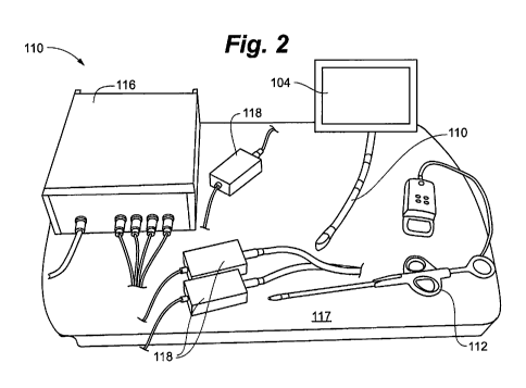
Figure 2 is a perspective view of a surgical navigation system according to an
embodiment of the present invention.
3
CA 02856549 2014-05-21
WO 2013/082581 PCT/US2012/067563
Figure 3 is a partial view of a transesophageal echocardiogram probe that can
be used
with a surgical navigation system according to an embodiment of the present
invention.
Figure 4 is a perspective view of a heart valve repair system that can be used
with a
surgical navigation system according to an embodiment of the present
invention.
Figure SA is a partial perspective view of the heart valve repair system of
Figure 4.
Figure 513 is a partial perspective view of the heart valve repair system of
Figure 4.
Figure 6 is a partial perspective view of a heart valve repair system for use
with a surgical
navigation system according to an embodiment of the present invention.
Figure 7 is a partial perspective view of a heart valve repair system for use
with a surgical
navigation system according to an embodiment of the present invention.
Figure 8 is a partial perspective view of a heart valve repair system for use
with a surgical
navigation system according to an embodiment of the present invention.
Figure 9 is a partial perspective view of a heart valve repair system for use
with a surgical
navigation system according to an embodiment of the present invention.
Figure 10 is a perspective view of a calibration system for a surgical
navigation system
according to an embodiment of the present invention.
Figure 11 is a screenshot of a surgical navigation system according to an
embodiment of
the present invention.
Figure 12 is a screenshot of a surgical navigation system according to an
embodiment of
the present invention.
Figure 13 is a screenshot of a surgical navigation system according to an
embodiment of
the present invention.
Figure 14 is a screenshot of a surgical navigation system according to an
embodiment of
the present invention.
Figure 15 is a screenshot of a surgical navigation system according to an
embodiment of
the present invention.
Figure 16 is a screenshot of a surgical navigation system according to an
embodiment of
the present invention.
Figure 17 is a screenshot of a surgical navigation system according to an
embodiment of
the present invention.
Figure 18 is a screenshot of a surgical navigation system according to an
embodiment of
the present invention.
Figure 19 is a screenshot of a surgical navigation system according to an
embodiment of
the present invention.
4
CA 02856549 2014-05-21
WO 2013/082581 PCT/US2012/067563
Figure 20 is a screenshot of a surgical navigation system according to an
embodiment of
the present invention.
Figure 21 is a flowchart depicting steps of heart valve repair process
according to an
embodiment of the present invention.
While the present invention is amenable to various modifications and
alternative forms,
specifics thereof have been shown by way of example in the drawings and will
be described in
detail. It should be understood, however, that the intention is not to limit
the present invention to
the particular embodiments described. On the contrary, the invention is to
cover all
modifications, equivalents, and alternatives falling within the spirit and
scope of the present
invention.
DETAILED DESCRIPTION
In the following detailed description of the present invention, numerous
specific details
are set forth in order to provide a thorough understanding of the present
invention. However,
one skilled in the art will recognize that various embodiments of the present
invention may be
practiced without these specific details. In other instances, well-known
methods, procedures,
and components have not been described in detail so as to not unnecessarily
obscure aspects of
the present invention.
According to an embodiment of the present invention, a visualization
environment uses
tracking technology to locate both a heart valve repair tool and a
transesophageal
echocardiogram (TEE) probe in 3D space, making it possible to represent real-
time echo images
with virtual geometric models of both devices and interactively defined
anatomy within a
common coordinate system. Exemplary repair tools can include those disclosed
in U.S. Patent
Publication Nos. 2008/0188873, 2010/0174297, 2009/0105279 and 2009/0105751.
Sensors
from, for example, the Aurora (Northern Digital, Waterloo, Canada) magnetic
tracking system
(MTS) can be integrated into the repair tool and onto the TEE probe of a, for
example, Philips
iE33 ultrasound.
Geometric models of each device can be created with appropriate computer
software and
the tools appropriately calibrated. One embodiment of such geometric models
can be implanted
using the Visualization Toolkit
(http://www.vtk.orgidoc/release/5.0/htrniasses.html) using
spline filters and STL file readers found in the open-source VTK software
libraries. Specifically,
classes such as the vtkSTLREader and vtkSplineFilter can be utilized. Axes
with 1 Omm
markings can be projected from the virtual representation of the tool,
indicating the forward
5
CA 02856549 2014-05-21
WO 2013/082581 PCT/US2012/067563
trajectory of the tool and the direction of the opening jaws. The system
greatly facilitates a
surgeons' ability to plan the tool trajectory towards a desired target site,
such as a heart valve.
In addition to representations of the tools, tracking the TEE image data makes
it possible
to define anatomy of interest (aortic valve annulus, target location (e.g.,
mitral valve line of
coaptation), and regions to be avoided (e.g., mitral valve annulus) for
contextual purposes. In
the case of mitral valve repair, the objective is to identify the plane of the
mitral valve annulus in
order to be able to navigate the repair tool quickly and safely to the
appropriate place within the
valve annulus to proceed with the repair under. With regard to an aortic valve
repair, a primary
issue is identifying the critical structures associated with the valve so that
a new valve can be
placed in such a way that it does not block the coronary vessels fed by the
coronary ostia and
positioned appropriately with respect to the base of the aorta. In both types
of procedures, target
points can be indentified with ultrasound shown as three dimensional locations
in space that can
be fitted with lines, rigs or planes to identify the location of the coronary
ostia, annuli of the
valves, the line or plane defining the base of the valve or any calcifications
near the aortic valve.
As will be described further herein, each of these marked regions can be
updated to reflect its
motion during the procedure, using motion models acquired from pre-operative
images, by
extracting motion parameters from the intra-operativc ultrasound images, or by
implanting and
tracking one or more magnetically or sonically traced fiducial markers secured
close to or on the
respective target region.
This augmented reality system is designed to assist the surgeon with three
related
navigation tasks of; planning the access point and trajectory; maintaining a
safe and direct entry
through the mitral valve commisure into the left atrium, and establishing the
correct tool
orientation at the line of coaptation so the repair device can grasp the
flailing leaflet. As shown
in Figure 21 such a process 10 includes, prior to making the apical entry
incision, the
echocardiographer identifying a minimal number of tie-points along the
pertinent anatomy
(aortic valve annulus, mitral valve annulus, line of coaptation) at step 12.
From these
coordinates, at step 14 a series of coordinates are generated to represent
these features in virtual
space. Next, the surgeon uses a desired trajectory projection of the repair
tool determined at step
16 to plan the optimal entry point and orientation at step 18. After apical
access at step 20, the
surgeon simply orients and points the tool trajectory towards the desired
target site and advances
the tool at step 22, monitoring the virtual representations as seen on the
real-time echo image
data at step 24. By overlaying the virtual elements on the real echo image
data, the surgeon is
able to assess the accuracy and reliability of the virtual representations in
real time. Once at the
desired target location at step 26, the procedure can return to the standard
workflow for carrying
6
CA 02856549 2014-05-21
WO 2013/082581 PCT/US2012/067563
out the repair procedure at step 28, since additional guidance is no longer
needed. In addition,
any relevant structure that can be identified within or surrounding the heart
in ultrasound, with a
tracked electrophysiological device or which can be identified in preoperative
image and
registered into the ultrasound coordinate frame can be similarly incorporated
into the system.
One embodiment of a surgical navigation system 100 as described above is
depicted in
Figures 1 and 2. The primary components of the system include a magnetic
tracking system 102,
an ultrasound imaging system 104 and a computer 106 with one or more output
monitors 108. A
TEE probe 110 of the ultrasound imaging system 104 can be integrated with the
magnetic
tracking system 102. A heart valve repair device 112 can also interface with
the magnetic
tracking system 102.
The magnetic tracking system 102 can utilize sensors interfacing with each of
the TEE
probe 110 and the heart valve repair device 112 to track the location and
orientation of those
tools with respect to the magnetic field generator 117 of the system 102,
which can be placed on
the operating room table underneath the patient. This information can be used
to place both the
TEE probe 110 and the heart valve repair device 112 into a common virtual
environment. Each
of the sensors can communicate with the magnetic sensor control unit 116 that
is linked to each
sensor by a sensor interface unit 118. In one embodiment, the system 102 uses
the Northern
Digital Aurora magnetic tracking system. In such an embodiment, the magnetic
tracking system
102 is controlled using ND! API software 113 and interfaces with the
navigation application
suite 111 on the computer 106 with AIGS API software 114. The system can
utilize three
tracked sensors, one mounted to the TEE probe 110 and two mounted to the heart
valve repair
device. In other embodiments, greater or fewer sensors can be used with each
device. Although
described as using a magnetic tracking system 102 to track the ultrasound
probe and surgical
tools, it should be understood that various other tracking systems could be
utilized in accordance
with the present invention. For example, other types of tracking that could be
used include
acoustic, radio-frequency, fiber optic, image based and x-ray.
Referring now to Figure 3, there can be seen a TEE probe 110 that can be used
with
embodiments of the present invention. The TEE probe 110 includes an ultrasound
transducer
that interacts with the ultrasound system 104 to provide echo images, as is
known in the art. In
the present invention, at least one sensor 130 is mounted to the TEE probe
110. Sensor 130 can
be a six degree of freedom, magnetically tracked sensor. In one embodiment, as
shown in Figure
3, the sensor 130 is mounted on a side surface of the probe 110. In other
embodiments, the
sensor 130 can be mounted on an upper or lower surface of the probe or
integrated inside the
probe casing. Sensor 130 can be mounted to probe 110 with an adhesive, such
as, for example a
7
CA 02856549 2014-05-21
WO 2013/082581 PCT/US2012/067563
Loctite 3554 UV cured adhesive. Sensor 130 can be permanently or removably
mounted to probe
110. In one embodiment, sensor 130 can be a single use, disposable sensor that
can be utilized
due to potential sensor damage and clearning/sterilization issues that can
arise with long term
use. Sensor 130 can also be intergrated into a removably mountable cap that
can be mounted to
the probe 110 during a procedure and then removed for cleaning prior to a
subsequent procedure.
Figures 4-9 depict a heart valve repair device 112 that can be used with
embodiments of
the present invention. Device 112 generally includes a handle assembly 140 and
a capture
assembly 142 with an elongate shaft 144 extending therebetween. An actuator
146 is located at a
proximal end of the device 112 for operating capture assembly 142. As can be
seen in Figures
5A and 5B, capture assembly 142 can include a first clamping jaw 148 and a
second clamping
jaw 150. Clamping jaws 148, 150 are slidably disposably relative to each other
with actuator
and can be used to capture tissue, such as a heart valve leaflet,
therebetween. Once tissue is
captured between clamping jaws 148, 150 a needle 152 can penetrate the tissue
to insert a suture
154 into the tissue. Further details of heart valve repair devices useable
with the present
invention are disclosed in U.S. Patent Publication No. 20090105751. Although
one specific
heart valve repair device is shown, it should be understood that the present
invention can be
adapted for use with any type of heart valve repair device.
Repair device 112 as used with the present invention can incorporate two
sensors in
addition to the sensor 130 utilized with the TEE probe 112. In one embodiment,
a first sensor
156 can be disposed with a rubber cylinder positioned within a groove 158 in
the shaft 144 of the
device near the handle assembly 140. This sensor can be a five degree of
freedom magnetic
sensor that is used to track the opening and closing of the capture assembly
142 clamping jaws
148, 150. A second sensor 160 can also be disposed in a groove 162 in the
shaft 144. The
second sensor 160 can be a six degree of freedom magnetic sensor that is used
to track the
movement of the repair device 112 itself. In one embodiment, the second sensor
160 can be held
in the groove by an adhesive. Each sensor 156, 160 includes corresponding
wires 164, 166
through which the positional data is transmitted that are routed out of the
tool 112 and back to
the sensor interfaces 118 and sensor control unit 116. In one embodiment, the
wires 164 for the
first sensor are fixed to the shaft 144 at location 164a and again adjacent
the exit point of wires
164 from device at location 164b, with a length of slack 164c that allows the
sensor to move
along the shaft 144 when actuator 146 is employed to move the clamping jaws
148, 150. Wires
166 for second sensor 160 can be adhered to the shaft 144 until the wires 166
exit the device
112. Wires 164, 166 can exit through an opening 168 in the body of the repair
tool 112. In one
embodiment, opening includes a grommet through which the wires 164, 166
extend.
8
CA 02856549 2014-05-21
WO 2013/082581 PCT/US2012/067563
One or both of the heart valve repair device 112 and the TEE probe 110 can be
calibrated
for use with the system 100. In this context, calibration refers to the
process of defining the
coordinate frame of a device relative to the magnetic tracking sensors or
other sensors used to
track the device. Heart valve repair device 112 can be calibrated with a
calibration jig 170 such
as shown in Figure 10. The jig 170 is configured such that the tip of the
repair device 112 is
always in the same location when held in the jig 170. In one embodiment, the
jig 170 can
comprise two milled acrylic blocks. A reference sensor 172 is positioned near
the tip of the
repair device 112 and can be rigidly mounted to the jig 170. In one
embodiment, the sensor can
be an ND! Aurora sensor. The jig 170 can also include a series of divots 174
milled into the jig
170 near the tip of the repair device 112. In one embodiment, eight spherical
divots arc milled in
a non-symmetrical pattern. A geometric model of the jig 170 can be created
from a micro-CT of
the jig, with the origin of the model defined at the repair device 112 tip and
the z-axis extending
along the long axis of the repair device 112. Using the micro-CT data, the
locations of the
milled divots are then defined for the model. Then, a magnetically tracked
tool 176 is used to
calibrate the repair device 112 by interfacing the tool 176 with each of the
divots 174. In one
embodiment, a tip 178 of the tool 176 can be shaped to fit within the divots
174. In one
embodiment, the device 112 can be provided to an end user having been pre-
calibrated for use
during production.
The TEE probe 110 can be calibrated by using a magnetically tracked tool
intersecting
the ultrasound image plane. In one embodiment, the magnetically tracked tool
can be a
previously calibrated repair device 112. In one embodiment, the computer 106
can monitor the
accuracy of the calibration during a surgical procedure and warn the users of
potential
inaccuracies in the model. In such an embodiment, the system could also intra-
operatively
correct calibration errors during the procedure.
The ultrasound image data acquired by the TEE probe 110 is transmitted from
the
ultrasound system 104 to the computer 106 for integration into the virtual
scene created with the
system 100. The data can be transferred from the ultrasound system 104 to the
computer with a
converter 120. In one embodiment, the converter is the Epiphan DVI2USB
converter. In such
an embodiment, the converter 120 can be managed by the Epiphan Application
Program
Interface 121.
The computer 106 operates to integrate image data from the ultrasound system
104 with
tracking information from the magnetic tracking system 102 to present virtual
representations of
the heart valve repair tool 112 and TEE probe 110 in a common 3D environment.
Using the
tracked TEE image data, geometric models of pertinent anatomy, such as mitral
and aortic valve
9
CA 02856549 2014-05-21
WO 2013/082581 PCT/US2012/067563
annuli, are added to provide the surgeon with a significantly more intuitive
environment for
performing the surgical procedure, as will be described in more detail below.
In one embodiment, two monitors 108 are used to provide a split screen view of
the
system. In such an embodiment, one monitor can be used for viewing by the
surgeon and the
other can be used by the echocardiographer and technician. In other
embodiments, only one
monitor can be used or more than two monitors can be used.
The computer 106 can operate a software platform that provides an augmented
reality
viewpoint for a surgeon performing a procedure, such as repair of a heart
valve. The software
platform provides the system for integrating the real-time information from
the magnetic
tracking system 102 with the real-time information from the ultrasound system
104, 110. The
information is displayed on a user interface 200 on the one or more computer
monitors 108
showing the ultrasound image data with dynamic virtual geometric
representations of surgical
tools 202 and anatomy 204 as will be discussed in more detail with regard to
Figures 11-20.
To establish the user interface, the software platform must render the various
components
for display on the interface. The body or shaft 144 of the heart valve repair
device 112 can be
rendered on the system as a solid shape derived from CAD drawings of the
device. Either a
portion of the length of the body of the device (e.g., 2 cm or 4 cm) or the
full body can be
rendered. The tip or capture assembly 142 can also be generated from CAD
drawings using the
same calibration matrix as the body. The location where the needle 152 used by
the device to
penetrate tissue exits from the shaft 144 can be marked with a sphere 206. The
sphere can define
two axes, a first axis 208 can be aligned with the direction of the tool
trajectory and a second
axis 210 can be orthogonal to the first axis 208. Repair device 112 can be
displayed either as
opaque or transparent object. In one embodiment, the device 112 automatically
fades to
transparency as it approaches target tissue, with distances at which this
occurs selectable by the
user. In such an embodiment, the sphere marker 206 showing the location of the
needle can
remain opaque at all times.
Figure 13 depicts an opening screen 220 of the user interface 200 according to
an
embodiment of the present invention. Opening screen 220 can include a general
functions render
pane 222 that allows rendering of an object to be manipulated and a module
render pane 224 for
displaying specific operations that can be undertaken in a given module. The
scene render pane
226 will display the navigation data for a given procedure. A drop down menu
228 can be used
to access the user interfaces for various modules.
A tracked tool module 230 is displayed in Figure 14. A tracked tools dialog
window 232
shown in Figures 15-18 can be opened by selecting the corresponding button 233
on the tracked
CA 02856549 2014-05-21
WO 2013/082581 PCT/US2012/067563
tool module 230. A tracker pull down menu 234 can be used to select a specific
tracked tool.
Once a tool is selected, tracker control buttons 236 can be used to control
tracking of the tool.
The opacity of all tools can be controlled with the global tool opacity slider
238. Opacity of a
specific tool can also be adjusted on the tracked tool module 230 by selecting
from the tool pull
down bar 240 and using the corresponding slider 242. Display of the selected
tool in wirefiume
and display of the tool axes can also be turned off and on with corresponding
check boxes 244,
246 on the tracked tool module 230.
Figures 15-18 display various aspects of the tracked tools dialog window 232,
which can
provide the basic functionality of the tracked tool module 230 as well as
additional functionality.
A tracker pane 248 of the window 232 is shown in Figure 15, and includes a
tracker pull down
menu 234 and tracker control buttons 235. A tool pull down menu 240 allows
selection of a
specific tool. A new tracking system box 251 allows a new system to be added
with an initialize
tracker button 250 to actuate the new system. A specific configuration for a
tracking can be
loaded or saved with buttons in the configuration box 252.
A tool actor pane 252 of the tracked tools dialog window 232 is shown in
Figure 16. The
tool actor pane 252 allows all virtual actors to be interactively modified in
real time. The tool
actor can be selected from a tool actor dropdown 254 and a new tool can be
rendered with the
add tool button 256 after an acting tool is selected. Various information on
the tool can be
provided and modified in the information box 258. Callbacks for the tool are
contained in a
callbacks box 260. Video sources for use with the tracked tool can be added,
removed and
viewed in the video sources box 262.
The tool calibration matrix 266 is displayed on a tool calibration pane 264 of
the dialog
box 232 as shown in Figure 17. The matrix can be manually entered into the
boxes or can be
copied and pasted into a text box 268. Various matrix controls 270 for
manipulating the data arc
also provided. A tip calibration box 272 can allow calibration of a tool tip
and can also display
the root mean squared error of the calibration 274. The orientation and tip
location of a tool can
also be obtained from a previously saved tool with the orientation box 276. A
command box 278
can alternatively be used to manually calibrate the rotation and translation
controls. The tracked
tools dialog window 232 can also include a video capture pane 280 as shown in
Figure 18. This
pane can provide for selection of a specific source video card from a pull
down menu 282 and
display information 284 about the source.
An anatomical feature module 286 is shown in Figure 19. A drop down menu 288
and
associated controls allow a specific anatomical feature to be selected, added
or removed, such as
for example, the mitral valve or the aortic valve. Various controls 290 can be
used to adjust the
11
CA 02856549 2014-05-21
WO 2013/082581 PCT/US2012/067563
rendering of the anatomical feature 289. A plurality of function keys 292 is
also provided. Keys
292 can be used to manage tie points 294, which can be denoted by small
spheres on the
interface 200. Tie points 294 can be one or more 3-dimensional points
representing a tracked
location on an anatomical landmark such as the annulus of the mitral valve or
aortic valve or
other structure as described earlier. The tie points can be used to create a
model of the structure
with a suitable curve. Tie points can also be displayed to represent specific
points on the
structure, such as a desired grasping point along a valve leaflet. The
save/load data buttons 296
allow tie points to be saved into the system or loaded from memory. A manage
data menu 298
allows the tie point data to be edited and removed. In an alternative
embodiment, tic points can
be selected and defined on the ultrasound device 104, rather than on the
computer 106.
In one embodiment, anatomical structures can be tracked as they move, either
by using
image-based tracking or by introducing tracked sensors close or attached to
the anatomical
structures. The tracking information can be used to dynamically update the
virtual
representations of the anatomy created with the tie points. An advantage of
updating the target
regions dynamically during the procedure is that in the case of mitral valve
repair, the repairing
instrument is less likely to be inadvertently guided into an inappropriate
structure, causing
potential damage. In the case of the aortic valve, the advantage of
dynamically moving the
target structures is that the procedure can be carried out without temporarily
stopping the heart or
inducing rapid pacing, both of which would stop the target motion, but would
add additional risk
to the patient.
A repair device module 271 is shown in Figure 20. The scene render pane 226
displays
the tracked repair tool 112 and TEE probe 110. Functions buttons 273 can be
used to control
various aspects of the devices. Various viewpoints from which the user can
view the procedure
can be selected and modified with viewpoints controls 275. The scene render
pane 226 can
display viewpoints in various ways, including a single view, a split, two pane
view and a four
pane view. The viewpoint of the virtual camera for a specific view can be
controlled with the
computer mouse, which can rotate, pan, zoom, etc. the view, to allow the user
to define a specific
view. One view that can be utilized is a barrel view, which sets the camera a
set distance, such
as 10 cm, above the repair tool 112 aligned along the main axis of the tool
112. Barrel view can
be activated with a corresponding function button 273. In an alternative
embodiment, rather than
the user defining and controlling the viewing angles for the augmented virtual
reality scene, the
viewing angles can be automated for a specific type of procedure. Views can
also be based on
pre-operatively acquired data. In an alternative embodiment, the images can be
displayed
stereoscopically to the observer. Navigation output controls 277 provide
tracking and control of
12
CA 02856549 2014-05-21
WO 2013/082581 PCT/US2012/067563
data relating to navigation of the repair device 112 to the target tissue
structure and grasping
controls 279 provide tracking and control of data relating the grasping
function of the repair tool
112 clamping jaws 148, 150. These tracking functions can be activated
manually, or can be
performed automatically and can provide for recording, storage and later
playback. Automatic
opacity of the tool at specific distances from the target site can be
controlled with opacity
controls 281.
It has been found that a surgical navigation system such as system 100 can
significantly
reduce the surgical time needed to perform a minimally invasive procedure,
such as repair of a
heart valve leaflet. In one study, the mean task completion time fell by a
factor of almost six
when using such a system. Such a system also leads to more direct navigation
paths to the target
tissue, which results in a safer procedure. For example, in repair of a heart
valve leaflet, a repair
device can inadvertently enter an area dangerous to a patient, such as the
left ventricular outflow
tract or cause damage to the leaflet itself when the path to the tool is not
guided as described
herein.
Although described herein as providing surgical navigation for capturing heart
valve
leaflets, embodiments of the present invention can also be applied to
targeting any intracardiac
structure for repair or replacement, such as full valve replacement or other
structural heart repair.
Sutures and other repair devices can be delivered via the disclosed system for
repair purposes.
In a further embodiment, a surgical navigation system as described herein can
be utilized
as a training system. Thus, in lieu of utilizing the system to aid in guiding
an actual surgical
procedure, the system can be utilized to train surgeons, echocardiographers
and others for
performing heart repair procedures.
Various embodiments of systems, devices and methods have been described
herein.
These embodiments are given only by way of example and are not intended to
limit the scope of
the present invention. It should be appreciated, moreover, that the various
features of the
embodiments that have been described may be combined in various ways to
produce numerous
additional embodiments. Moreover, while various materials, dimensions, shapes,
implantation
locations, etc. have been described for use with disclosed embodiments, others
besides those
disclosed may be utilized without exceeding the scope of the invention.
13