Note: Descriptions are shown in the official language in which they were submitted.
CA 02856739 2015-09-02
HEATED WET GAS FLOW METER
FIELD OF INVENTION
[0001] This invention relates to methods and apparatus to measure properties
of a wet gas
flow.
DESCRIPTION OF RELATED ART
[0002] Thermal anemometer type flow meters have a very wide dynamic range,
100:1 and in
some cases up to 1000:1. In addition, they have good durability, good
accuracy, and high
repeatability, and they have long proven themselves in the measurement of dry
gas flow in a
variety of applications. However, thermal anemometer type flow meters are very
sensitive to
liquid in the gas stream since any liquid contacting the sensor probes will
cause a high
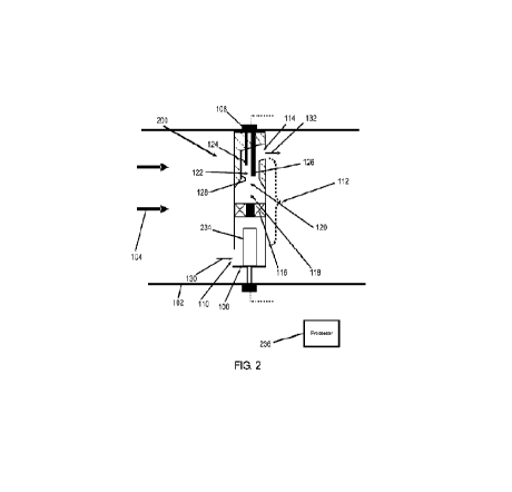
erroneous reading. Nonetheless, the significant advantages of a thermal
anemometer type
flow meter make it highly desirable to develop one that can operate in wet gas
flows.
SUMMARY
[0002a] In one embodiment there is provided a flow measurement system for a
duct. The
system includes a flow body flow meter receiving a wet gas stream that is a
small portion of a
larger stream in the duct. The flow body flow meter includes a tube like flow
body including
a lateral inlet at a first end of the flow body, a lateral outlet at a second
end of the flow body,
and a longitudinal internal passage coupling the inlet and the outlet, wherein
the inlet receives
the stream and the outlet returns the stream from the flow body back into the
duct and a heater
evaporating at least some liquid droplets present in the stream flowing
through the flow body.
The flow body flow meter also includes an angular momentum inducing device
across a width
of the internal passage to induce a rotating flow to the stream, wherein the
angular momentum
inducing device is an axial swirler, an auger, or a cyclone and a thermal
anemometer flow
sensor having a temperature sensing probe and a heated probe placed centrally
in the internal
passage, wherein the sensor measures a property of the stream.
- 1 -
CA 02856739 2015-09-02
[0002b] In another embodiment there is provided a flow measurement system for
a duct. The
system includes a flow body flow meter receiving a wet gas stream that is a
small portion of a
larger stream in the duct. The flow body flow meter includes a tube like flow
body including a
lateral inlet at a first end of the flow body, a lateral outlet at a second
end of the flow body,
and a longitudinal internal passage coupling the inlet and the outlet, wherein
the inlet receives
the stream and the outlet returns the stream from the flow body back into the
duct, a heater
evaporating at least some liquid droplets present in the stream flowing
through the flow body,
wherein the heater is a cylindrical heater that extends longitudinally into
the flow body from
an inlet end of the flow body and a sensor having one or more sensor probes in
the internal
passage, wherein the sensor measures a property of the stream.
[0002c] In another embodiment there is provided a method involving mounting a
tube-like
flow body inside a duct to divert a wet gas stream from a large stream in the
duct and then
return the stream to the duct, the flow body being oriented normal to the
duct, the flow body
including a lateral inlet facing into the large stream at a first end of the
flow body, a lateral
outlet facing away from the large stream at a second end of the flow body, and
a longitudinal
internal passage coupling the inlet and the outlet. The method also involves
heating the stream
within the flow body to evaporate at least some liquid droplets present in the
stream and
measuring a property of the stream within the flow body with a sensor inserted
into the flow
body, the sensor having one or more sensor probes in a portion of the stream
that is
substantially free of the liquid droplets.
BRIEF DESCRIPTION OF THE DRAWINGS
[0003] In the drawings:
- 2 -
CA 02856739 2015-02-05
Fig. 1 shows a cross-sectional view of a flow body flow meter representing
embodiments
of a flow body flow meter;
Fig. 2 shows a cross-sectional view of a heated flow body flow meter with a
cylindrical
heater;
Fig. 3 shows a cross-sectional view of a heated flow body flow meter without a
swirler;
Figs. 4A, 4B, and 4C show cross-sectional, front, and isometric views of a
heated flow
body flow meter with the inlet designed as an impactor;
Fig. 5 shows a cross-sectional view of a heated flow body flow meter with a
metal tube
heater;
Fig. 6 shows an isometric view of a swirler; and
Fig. 7 shows a cross-sectional view of a heated flow body flow meter, all
arranged in
accordance with embodiments of the present disclosure.
[0004] Use of the same reference numbers in different figures indicates
similar or identical
elements.
[0005]
DETAILED DESCRIPTION
[0006] Co-pending U.S. Patent App. Ser. No. 12/817,211 discloses embodiments
of a flow
body flow meter for measuring a fluid property, such as flow rate, of a wet
gas stream in a
pipe or duct. A flow body is a structure placed in or connected to a flow
stream within a duct
through which a portion of the flow in the duct can pass. A flow body flow
meter is a flow
body which contains a flow measuring device. A wet gas stream is defined as a
gaseous
stream that at least intermittently contains liquid droplets (e.g., steam that
contains water
droplets). The liquid droplets may be the same or different sizes. A portion
of the wet gas
stream enters the flow body of the meter. The flow body imparts angular
momentum to the
- 2a -
CA 02856739 2015-02-05
wet gas stream to drive denser liquid droplets to the outside of the rotating
flow, thereby
creating a central portion of the rotating flow that is essentially free of
the liquid droplets and
allowing a sensor in the flow body to measure the flow rate of the wet gas
stream. When the
imparted angular momentum is low and/or the liquid droplets are small, the
liquid droplets
may not be effectively separated from the central portion of the rotating
flow.
- 2b -
CA 02856739 2014-05-22
WO 2013/090880
PCT/US2012/070009
[0007] One solution to this problem for a wet gas stream in a given pipe
diameter is to reduce
the diameter of the pipe to cause a higher flow velocity in the flow body and
create a higher
angular momentum to provide better separation of the small liquid droplets.
However, such a
reduced flow pipe diameter would result in an undesirable increase in pressure
drop in the
pipe. Another alternative solution is to heat the entire wet gas stream to a
higher temperature
such that all the liquid droplets evaporate and then measure the flow of the
single phase
gaseous flow. However, this is also undesirable since heating the entire wet
gas stream to the
temperature necessary to evaporate all the liquid droplets would require an
undesirably large
energy input and could disrupt the process by changing the stream temperature.
Additionally,
the costs associated with heating a length of processing piping is expensive
and in many
cases impractical to vaporize all the liquid droplets in the wet gas stream.
[0008] Fig. 1 shows a cross-sectional view of a flow body flow meter 100
representing
embodiments of the flow body flow meter disclosed in U.S. Patent App. Ser. No.
12/817,211.
Meter 100 is located in a pipe or duct 102 through which flows a wet gas
stream 104 that at
least intermittently contains liquid droplets (e.g., steam that contains water
droplets). Many
orientations of duct 102 and meter 100 are possible. In one or more
embodiments, meter 100
in mounted normal to the bottom of a horizontal duct 102 so the inlet end is
located above the
outlet end. However other configurations may have the outlet above the inlet.
[0009] Meter 100 includes a flow body 106 and a sensor 108 in the flow body.
Flow body
106 is tube like with a lateral inlet port 110, an internal passage 112
downstream from the
inlet, and a lateral outlet port 114 downstream from the internal passage.
Inlet port 110 faces
into stream 104 while outlet port 114 faces away from the stream. The velocity
of stream 104
in duct 102 generates a high static pressure at inlet port 110 and a low
static pressure at outlet
port 114 so that a portion of the flow in the main duct 102 is forced to flow
through flow
body 106. Internal passage 112 provides a rotational path that imparts angular
momentum to
a portion 130 of the stream (also called "inlet stream 130") that enters flow
body 106 through
inlet port 110 and exits from outlet port 114 as a portion 132 of the stream
(also called "outlet
stream 132").
[0010] Sensor 108 is located near the outlet section of flow body 106. Sensor
108 may be a
flow sensor, such as a thermal anemometer that can measure mass flow,
volumetric flow, or
flow velocity. Alternatively, sensor 108 may be a different type of sensor
that measures
- 3 -
CA 02856739 2014-05-22
WO 2013/090880
PCT/US2012/070009
temperature, heat capacity, density, viscosity, humidity, and other fluid
properties thus
allowing meter 100 to measure these properties without interference from the
liquid droplets.
[0011] Internal passage 112 includes an axial swirler 116 or another similar
device
downstream from inlet port 110. Internal passage 112 may further include a
wide cylindrical
section 118 downstream from swirler 116, a narrowing section 120 downstream
from the
wide cylindrical section, and a narrow cylindrical section 122 downstream from
the
narrowing section. Narrowing section 120 reduces the flow area downstream from
swirler
116. Narrowing section 120 may reduce the flow area by a contraction ratio
(flow cross
sectional area of wide cylindrical section 118 divided by flow cross sectional
area of narrow
cylindrical section 122) of 0.9 to 0.2, 0.8 to 0.4, or 0.7 to 0.4. Narrowing
section 120 may
have a conical shape. From the outlet end of flow body 106, probes 124 and 126
of sensor
108 extend axially into narrow cylindrical section 122 so they are located
near the center axis
of the narrow cylindrical section and away from an interior wall 128 of the
narrow cylindrical
section.
[0012] The velocity head of stream 104 causes inlet stream 130 to enter flow
body 106
through inlet port 110 and exit outlet port 114 as outlet stream 132. Swirler
116 imparts
rotation or angular momentum to the stream inside flow body 106 to drive the
denser liquid
droplets to the outside away from the gas particles near the center of the
rotating flow such
that a substantially liquid free portion of the stream flows over sensor
probes 124 and 126.
This arrangement provides a flow measurement of the stream within flow body
106, which
can be related to the flow rate or other fluid properties of stream 104
through calibration
curves, graphs, tables, equations, or other similar means.
[0013] An example of swirler 116 is later described in reference to Fig. 6.
Swirler 116 may
be replaced with any structure, flow path, internal passage, or device that
imparts angular
momentum to inlet stream 130 and causes the denser liquid droplets to be
separated from a
portion of the stream that flows over sensor probes 124 and 126. Examples of
such angular
momentum inducing devices include augers, cyclones, angled inlet ports,
impactors, and
other designs mentioned in U.S. Patent App. Ser. No. 12/817,211.
[0014] The contraction in internal passage 112 from narrowing section 120 may
reduce or
eliminate any recirculation zone in the center of the stream that develops
just downstream of
swirler 116. Such a recirculation zone may disturb the flow over sensor probes
124 and 126
- 4 -
CA 02856739 2014-05-22
WO 2013/090880
PCT/US2012/070009
of sensor 108 and cause the liquid droplets to impact the sensor probes. The
contraction in
internal passage 112 may also increase the stream velocity and the rotational
velocity to
enhance the centrifugal force and thus be more effective in driving the liquid
droplets to the
outside of the flow path.
[0015] As noted above, when the liquid droplets are small and/or the flow
velocity is low, the
imparted angular momentum may not be sufficient to separate the denser liquid
droplets from
the gas particles in the center portion of the rotating flow. This allows some
of the liquid
droplets to impact probes 124, 126 and cause an error in the flow measurement.
Embodiments of the present disclosure address this problem by adding heat to
inlet stream
130 within a flow body to vaporize at least some of the liquid droplets in the
stream.
EMBODIMENTS OF HEATED FLOW BODY FLOW METER
[0016] Fig. 7 shows a cross-sectional view of a heated flow body flow meter
700 in one or
more embodiments of the present disclosure. Meter 700 is located in duct 102
through which
flows wet gas stream 104 that at least intermittently contains liquid
droplets. Meter 700
includes a flow body 706 and a sensor 708 in the flow body. Flow body 706 is
tube like with
an inlet port 710, an internal passage 712 downstream from the inlet, and a
lateral outlet port
714 downstream from the internal passage. Inlet stream 130 (e.g., 1 to 20% of
stream 104)
enters inlet port 710 and exits from outlet port 714 as outlet stream 132.
Similar to meter
100, many orientations of duct 102 and meter 700 are possible.
[0017] Stream 130 going through flow body 706 first passes through a region
734 that
includes one of a heater, a heater combined with a mixer, a heater combined
with a liquid
droplet separator, or a heater combined with a mixer and a liquid droplet
separator. The
heater, the mixer, and the liquid droplet separator may be combined in any
order, and are
hereafter referred to as "component 734." Downstream of component 734 is
sensor 708 that
measures some property of the flow. Component 734 vaporizes and/or separates
the liquid
droplets in stream 130 so that the flow over sensor 708 consists of vapor only
and the
properties measured are the properties of the gas phase. As described above,
sensor 708
could be a thermal mass flow meter that is sensitive to liquid droplets. Since
component 734
eliminates and/or separates the liquid droplets so that only vapor flow passes
over sensor 708,
meter 700 may measure mass flow properly. Since the fraction of stream 104
flowing
through meter 700 and over sensor 708 is fixed, meter 700 may be calibrated to
give an
- 5 -
CA 02856739 2014-05-22
WO 2013/090880
PCT/US2012/070009
accurate measure of the velocity of stream 104 independent of the presence of
liquid droplets
in the main stream 104. As will be shown in subsequent figures and in the
figures of co-
pending U.S. Patent App. Ser. No. 12/817,211, meter 700 may take a number of
different
forms and orientations.
[0018] Fig. 2 shows a cross-sectional view of a heated flow body flow meter
200 in one or
more embodiments of the present disclosure. Meter 200 is a variation of meter
700 in Fig. 7.
Meter 200 is similar to meter 100 in Fig. 1 but inverted so inlet port 110 is
located below
outlet port 114. More importantly meter 200 includes a cylindrical heater 234
located near
the inlet section of flow body 106. Heater 234 may extend axially into flow
body 106 from
the inlet end. Heater 234 may be a cartridge heater with inner resistance
wires that heat the
outer heater surface.
[0019] Inlet stream 130 enters inlet port 110 and passes around heater 234
before entering
swirler 116. Heater 234 adds heat to inlet stream 130 to raise its temperature
and vaporize
some or all of the liquid droplets in the stream. A small amount of heat may
be added to inlet
stream 130 to evaporate smaller liquid droplets while larger liquid droplets
are separated by
swirler 116 from a central portion of the rotating flow. A large amount of
heat may be added
to stream 130 to vaporize all the liquid droplets. In either scenario, a
gaseous flow free of
liquid droplets passes over sensor probes 124 and 126 and sensor 108 measures
the flow rate
of the gaseous flow. A processor 236 is coupled to receive the sensor signals
from sensor
108 and control the power input to heater 234. Processor 236 relates the
sensor signals to the
flow rate or other fluid properties of stream 104 through calibration curves,
graphs, tables,
equations, or other similar means.
[0020] For situations where there is a high flow velocity in duct 102 and the
liquid droplets
are not too small in diameter, the velocity head generates sufficient flow
velocity in flow
body 106 such that swirler 116 or another similar device imparts a high
rotational velocity to
inlet stream 130 within the flow body to drive substantially all the liquid
droplets to interior
wall 128 of the flow body and allow only a gaseous flow to contact sensor
probes 124 and
126. Under such conditions, where the flow velocity is above a threshold and
the droplet size
is sufficiently large, swirler 116 imparts sufficiently high angular momentum
to inlet stream
130 within flow body 106 such that substantially all the liquid droplets are
removed from the
gaseous flow and no heating of the stream is needed. The flow rate range where
swirler 116
induces sufficient angular momentum varies with the liquid droplet size. For a
large droplet
- 6-
CA 02856739 2014-05-22
WO 2013/090880
PCT/US2012/070009
size, the flow rate range for which swirler 116 is sufficient may extend to
relatively low flow
rates. For a small droplet size, the minimum flow rate to remove substantially
all the liquid
droplets from the gaseous flow may be much higher.
[0021] Since inlet stream 130 passing through flow body 106 is a small
fraction of the main
stream 104, the energy input to heater 234 should be small. In addition, when
outlet stream
132 is returned to the main stream 104, the change in temperature of the main
stream should
be negligible.
[0022] Locating inlet port 110 below outlet port 114 helps to avoid the
"chimney" effect in
low flow situations where the flow rises when the driving force from stream
104 is unable to
push stream 130 down flow body 106. The chimney effect may be amplified by the
presence
of heater 234, which creates a heat plume that rises and pushes against stream
130.
[0023] Fig. 3 shows a cross-sectional view of a heated flow body flow meter
300 in one or
more embodiments of the present disclosure. Meter 300 is similar to meter 200
in Fig. 2 but
uses heater 234 without swirler 116. Meter 300 may be used for low flow rates
and small
liquid droplets. Meter 300 may also be used for larger liquid droplets if the
temperature rise
is sufficiently high. Heater 234 raises the temperature of inlet stream 130
flowing into inlet
port 110. This increased temperature vaporizes the small liquid droplets
before they can
reach sensor probes 124 and 126 so that sensor 108 measures a gaseous flow and
is not
influenced by the liquid droplets in inlet stream 130. In one or more
embodiments, meter 300
may include an optional static mixer 338 downstream of heater 234 so that the
gaseous flow
over sensor probes 124 and 126 is well mixed with minimal variations in
temperature. In one
or more embodiments, the cross-sectional area of inlet port 110 is sized to
reduce the flow
within flow body 106, thereby allowing heater 234 to effectively vaporize the
liquid droplets
at higher flow rates and allowing operation at higher flow velocities. Meter
300 may also be
used in streams with larger liquid droplets as long as the temperature rise is
large and/or
residence time of the heated flow region in flow body 106 is sufficiently long
such that the
larger droplets will be substantially vaporized.
[0024] Heating stream 130 within flow body 106 to vaporize the liquid droplets
and then
measuring the gaseous flow may give a different mass flow measurement compared
to a
swirler or other similar device that separates the liquid droplets from the
gaseous flow and
then measures the mass flow of the gaseous flow. In the first case, when inlet
stream 130 is
- 7 -
CA 02856739 2014-05-22
WO 2013/090880
PCT/US2012/070009
heated sufficiently to vaporize all the liquid droplets, the measured mass
flow may be the sum
of the gaseous flow and the liquid flow and may in effect give a flow reading
equal to the
total flow within flow body 106. In the second case, when inlet stream 130 is
not heated and
the liquid droplets are separated by a swirler, the measured mass flow may be
the mass flow
of the gaseous flow only. These two mass flow measurements may not be
significantly
different for most applications of interest where the mass flow of the liquid
flow is generally
small, typically 2 to 3% or less. However, even in cases where the liquid mass
fraction is
higher, the embodiments of the present disclosure allow a measurement of the
mass flow
without the effects from the presence of the liquid droplets that otherwise
make any
measurement of mass flow difficult or impossible or necessitate the use of
more expensive
flow measurement instrumentation.
[0025] Figs. 4A, 4B, and 4C show cross-sectional, front, and isometric views
of a heated
flow body flow meter 400 in one or more embodiments of the present disclosure.
Meter 400
uses an inlet designed as an impactor to separate liquid droplets from gas
particles inside the
meter. Meter 400 is located in pipe or duct 102 through which flows stream 104
that at least
intermittently contains liquid phase droplets. Many orientations of duct 102
and meter 400
are possible. In one or more embodiments, meter 400 is mounted normal to the
top of a
horizontal duct 102 so the inlet end is located below the outlet end.
[0026] Meter 400 includes a flow body 406 and sensor 108 in the flow body.
Flow body 406
is tube like with a lateral inlet port 410, an internal passage 412 downstream
from the inlet,
and a lateral outlet port 414 downstream from the internal passage. Inlet port
410 faces
substantially into stream 104 while outlet port 414 faces substantially away
from the stream.
Inlet port 410 is a long narrow slot oriented along the length of flow body
406. A cylindrical
heater 434 extends axially into flow body 406 from the inlet end. Sensor 108
is located near
the outlet section of flow body 406.
[0027] Internal passage 412 includes a wide cylindrical section 418, a
narrowing section 420
downstream from the wide cylindrical section, and a narrow cylindrical section
422
downstream from the narrowing section. Narrowing section 420 may reduce the
flow area by
a contraction ratio of 0.9 to 0.2, 0.8 to 0.4, or 0.7 to 0.4. Narrowing
section 420 may have a
conical shape. Sensor probes 124 and 126 extend axially into narrow
cylindrical section 422
so they are located near the center axis of the narrow cylindrical section and
away from an
interior wall 438 of the narrow cylindrical section.
- 8 -
CA 02856739 2014-05-22
WO 2013/090880
PCT/US2012/070009
[0028] Cylindrical heater 434 extends axially into wide cylindrical section
418. To form an
impactor, cylindrical heater 434 is dimensioned so the annular separation
between the inner
diameter of wide cylindrical section 418 and the outer diameter of the
cylindrical heater is
small enough so inlet stream 130 entering through inlet port 410 makes an
abrupt turn to pass
around the cylindrical heater. This abrupt turn imparts angular momentum to
the flow stream
so the denser liquid droplets continue in an essentially straight line and
impact cylindrical
heater 434 while the gas particles flow around the cylindrical heater and then
up through the
rest of internal passage 412. The ratio between the dimensions of (1) the
width of inlet port
410, (2) the annular gap between the inner diameters of flow body 406 at the
region of heater
434 and the outer diameter of the heater, and (3) the inner diameter of the
flow body at the
region of the heater may be 0.05/0.05/1, 0.1/0.1/1, or 0.25/0.25/1.
[0029] Cylindrical heater 434 also adds heat to inlet stream 130 flowing
through flow body
406 and thus vaporizes the liquid droplets. The resulting flow into narrow
cylindrical section
422 is substantially free of the liquid droplets so that a gaseous flow passes
over sensor
probes 124 and 126 and sensor 108 measures the flow rate of the gaseous flow.
Alternative
impactor designs may be used instead of cylindrical heater 434. For example,
an impactor
may divert the flow through a sharp angle causing the higher density liquid
droplets to impact
a heated surface.
[0030] Processor 236 is coupled to receive the sensor signals from sensor 108
and control the
power input to heater 434. Processor 236 relates the sensor signal to the flow
rate or other
fluid properties of stream 104 through calibration curves, graphs, tables,
equations, or other
similar means.
[0031] Fig. 5 shows a cross-sectional view of a flow body flow meter 500 in
one or more
embodiments of the present disclosure. Meter 500 is similar to meter 200 in
Fig. 2 but uses a
heater 534 instead of a cylindrical heater 234. Heater 534 may be composed of
a long metal
tube that contains an electrical heating element through which an electric
current is passed to
heat the entire length of the long metal tube. Heater 534 may extend along the
external
surface of flow body 106 and enter the inlet section of the flow body or may
be incorporated
into the internal structure of flow body 106. Within the inlet section of flow
body 106, heater
534 has a section 540 that is wound in a spiral fashion to provide a large
heated surface area
to contact stream 130. Heater 534 may have a heated surface along its entire
length or just in
section 540 inside the inlet section of flow body 106. The shape of heater 534
may also take
- 9 -
CA 02856739 2014-05-22
WO 2013/090880
PCT/US2012/070009
other forms, such as a spiral, small diameter spirals within larger spirals,
zigzag shapes,
square shapes, or other shapes that expose a large surface area to heat inlet
stream 130.
Heater 534 may have a round cross section, a square cross section, or a flat
cross section.
Heater 534 may also contain an internal thermocouple with separate leads to
allow the
measurement of the temperature of the heater at one or more locations.
Additionally, heater
534 may contain a heater wire whose resistance changes with temperature so
that the
temperature or average temperature of the heater wire can be determined by
measuring the
resistance of the heater wire. In addition, this resistance measurement can be
used to control
the power to the heater wire.
[0032] Fig. 6 shows a swirler 116 of meters 200 and 500 (Fig. 2 and 5) in one
or more
embodiments of the present disclosure. Swirler 116 has angled vanes 602
arrayed around the
outside of a central hub 604. In one or more embodiment, swirler 116 may be
heated by
placing a heater 606 in central hub 604 so that vanes 602 are heated and then
vanes 602 heat
the flow through flow body 106. Swirler 116 may be used in addition or as an
alternative to
heaters 234 and 534 in meters 200 and 500, respectively.
[0033] In one or more embodiments of the present disclosure, a heater element
is affixed to
the inlet section of a flow body to heat the flow body itself. Stream 130
contacts the inside
surface of flow body and is thereby heated. The method of heating the flow
body may take
many forms. For example, a cartridge heater (such as heater 234 in Fig. 2) may
be affixed to
the external surface of the flow body or a wire type heating element (such as
heater 534 in
Fig. 5) may be wrapped around the external surface of the flow body.
Alternatively the
heater may be a heater circuit that passes an electric current directly
through a conductive
flow body or a portion of the flow body to directly heat the flow body by
resistive heating.
[0034] In one or more embodiments of the present disclosure, the heater
element is a thin
film heater. A thin film heater has a thin metal film deposited on a substrate
and receives an
electric current through the metal film to heat the metal film and the
substrate. The thin film
heater may be affixed to the interior of the flow body so that it heats both
the inlet stream and
the flow body, or the thin film heater may be affixed to the exterior of the
flow body so that it
heats the flow body and the flow body interior surface heats the inlet stream
within the flow
body.
- 10 -
CA 02856739 2014-05-22
WO 2013/090880
PCT/US2012/070009
[0035] The thin film heater may be constructed of a metal film on a ceramic
substrate, a
polymer substrate, or a composite substrate such as fiberglass reinforced
plastic typically
used in circuit boards. The metal film may be any electrically conductive
material. The
metal film may be of a metal or an oxide of a metal such as nickel, copper,
silver, gold,
platinum, palladium, or an alloy of these metals. The metal film could be
deposited in a
single trace, a zigzag trace, or in any form desired to provide resistive
heating in the location
desired.
[0036] In one or more embodiments of the present disclosure, alternative means
of heating
inlet stream 130 in a flow body includes microwave radiation, infrared
radiation, laser light,
circulating flow of a higher temperature heat transfer fluid, or other means
of applying energy
to the inlet stream itself or the inlet section of the flow body that are
common in the art. If
the liquid phase droplets in inlet stream 130 consist substantially of water
or hydrocarbons,
then microwave or infrared frequency could be tuned to provide heat directly
to the liquid
phase droplets.
[0037] The embodiments in Figs. 1 through 5 show a thermal anemometer type
flow sensor
employing two probes with one which measures the stream temperature and one
which is
heated. The signals derived from these sensor probes are then related to fluid
properties
through calibration curves, graphs, tables, equations, or other similar means.
U.S. Patent
Nos. 7,418,878 and 7,647,843 describe a multitude of strategies for operating
such a thermal
anemometer flow sensor. The flow body flow meters described herein can be used
with other
types of flow measurement technologies. For example, the flow in regions 120,
122 (Fig. 1)
or 418, 420 (Fig. 4) that is free of liquid droplets may incorporate an
ultrasonic flow
measurement device, a vortex shedding flow measurement device, an orifice or
venturi
combined with one of more pressure sensors to measure pressure drop, or other
flow
measurement sensor technologies.
TEMPERATURE COMPENSATION IN THE FLOW MEASUREMENT ALGORITHM
[0038] All flow meters show some effect of stream temperature on the flow
measurement.
For this reason, a flow meter that heats the stream will require that the flow
reading be
corrected for changes in the stream temperature. Thus, the embodiments of the
flow meters
in the present disclosure may include a temperature compensation algorithm in
processor 236
to apply to the sensor signals to give a corrected flow value. The correction
algorithm may
- 11 -
CA 02856739 2014-05-22
WO 2013/090880
PCT/US2012/070009
be a correction factor dependent only on the temperature, a correction table
dependent on
both the temperature and the flow rate, or a mathematical expression that
includes
temperature, flow, and other factors such as temperature rise due to heating
of the gas stream,
power input to the heater, heat loss from the heater, and other factors. The
correction
algorithm may be determined through calibration using known parameters.
CONTROL ALGORITHMS
[0039] In the embodiments of the present disclosure, processor 236 controls
the application
of heat to inlet stream 130 flowing through a flow body using a variety of
methods.
Processor 236 may hold the power input fixed or varied as a function of the
flow rate
measured by sensor 108. It is noted that by controlling the power input to the
heater at a
fixed level, the temperature rise of flow stream 130 would depend on the flow
rate since at
low flow rates the temperature rise is higher. It is the lower flow rate
situation where a larger
temperature rise is needed to evaporate liquid droplets that cannot be
separated from the
gaseous flow by the swirler, the impactor, or another similar device.
Alternatively, processor
236 holds the heater power low at a low flow rate and increases the heater
power as the flow
rate increases. In one or more embodiments, processor 236 adjusts the heater
power to obtain
a target temperature. For example, one of sensor probes 124 and 126 may be a
temperature
sensor that measures the temperature of stream 130 flowing through the flow
body.
Processor 236 then adjusts the heater power to obtain a target temperature at
the temperature
sensing probe. This target temperature may be a function of the measured flow
rate.
[0040] In one or more embodiments, a temperature sensor separate from sensor
108 is used
to measure the temperature of inlet stream 130 and processor 236 adjusts the
heater power to
obtain a target temperature at sensor probes 124 and 126 so the target
temperature represents
a target temperature rise in the inlet stream. The temperature rise may be a
function of the
measured flow rate.
[0041] In one or more embodiments where a meter includes both a swirler and a
heater (e.g.,
meter 200 in Fig. 2), processor 236 operates the heater at constant power such
that the heater
provides sufficient heat to vaporize substantially all the liquid droplets but
especially the
small liquid droplet at low gas flow rates within the flow body. As the fluid
velocity in the
duct or pipe increases and the flow rate within the flow body increases, the
added heat
becomes insufficient to vaporize the smaller liquid droplets but the flow
velocity becomes
- 12 -
CA 02856739 2014-05-22
WO 2013/090880
PCT/US2012/070009
sufficiently high such that the angular momentum induced by the swirler
separates the liquid
droplets from the gas particles, thereby allowing the measurement of the
gaseous flow.
[0042] In one or more embodiments, a meter incorporates temperature
measurements at the
inlet and the outlet of the flow body and processor 236 adjusts the power to
the heater to
obtain a target outlet temperature that is a fixed value, a function of the
inlet temperature, a
function of the flow rate, or a function of other characteristics of the flow
stream. The meter
may include temperature sensors at the inlet and the outlet of the flow body.
Alternatively,
the outlet temperature measurement may be performed by one of sensor probes
124 and 126.
FLOW METER ORIENTATIONS
[0043] U.S. Patent App. Ser. No. 12/817,211 describes a number of different
designs for a
flow body flow meter including designs that orient the flow body vertical up
from the bottom
of the duct, designs that orient the flow body vertically down from the top of
the duct,
designs that orient the flow body co-linearly with the flow in the duct,
designs that place the
flow body in a side passage with a portion of the flow in the main duct
passing outside the
duct and through the flow body, etc. All of the different designs may use the
flow meters
described herein.
[0044] Various other adaptations and combinations of features of the
embodiments disclosed
are within the scope of the invention. Numerous embodiments are encompassed by
the
following claims.
- 13 -