Note: Descriptions are shown in the official language in which they were submitted.
CA 2,856,775
Blakes Ref.: 11148/00001
GUY ANCHOR REMEDIATION APPARATUS
RELATED APPLICATIONS
This application claims priority to and is a non-provisional of United States
Provisional
Patent Application No. 61/911,109 filed December 4, 2013, entitled "Guy Anchor
Remediation
Apparatus".
FIELD OF THE INVENTION
[001] A reinforcing system and/or means for reinforcing guyed structures or
guyed
construction techniques by supplementing or retrofitting the current anchoring
system with a
revised anchoring system which attaches or adapts to the current anchoring
system.
BACKGROUND OF THE INVENTION
[002] Towers and transmission towers are utilized in multiple industries
including radio,
television, and cellular phone. Towers are also used in the power transmission
and wind turbine
industries. One type of tower (or structure) is known as a guyed structure or
alternatively an
additionally guyed structure. In both, guy wires (or guy anchors) are attached
when the
construction has to withstand strong forces in a certain direction (typically
wind). Guy wires assist
in maintaining the structure in a vertical position. In a standard arrangement
the structures having
a main body (mast) which stands on top of a base. The base usually being a
concrete structure
or slab, or any number of materials able to maintain the loads required. Guy
wires then attach to
the structure/mast and extend down and away from the mast. The guy wires are
fixed securely
to the ground via an anchor.
[003] Triangulation is often employed as the means of securing the
structures, though
any number (1,2,3,4 and more) of guyings are possible to secure a structure.
In a triangular setup
at least three guy anchors are provided approximately 120 degrees from one
another to provide
a stable means of keeping the mast vertical. In other embodiments the
structure utilizes more
than 3 guy anchors either in an array circumferentially around the mast or by
attaching at various
heights along the mast. Other known structures include H-framed structures
(which require
addition guying, such as 6, 12 or more guying arrangements), utility poles,
signs, billboards,
electrical substations, water tanks, turbines, stacks and other structures.
23684108.1
CA 2856775 2019-07-02
CA 02856775 2014-07-10
CA Application
Blakes Ref.. 11148/00001
[004] The termed "guyed structure" being a structure whose masts have no
independent means of support, relying entirely on guy wires to hold them
upright. The term
"additional guyed structures" being a structure which needs guy wires for
reinforcement and
stability. A guyed structure or an additional guyed structure being cheaper
than a completely
free-standing structure, while withstanding the same force(s). Guying can also
allow for an easy
upgrade of existing structures. The disadvantages of guying is that it
requires more ground
space than a free standing structure and that the guy anchors may handicap
nearby agriculture.
There also exists the danger that the guys could be damaged at their anchors,
requiring fencing
to keep potential vandals away.
[005] One major problem regarding guyed structure anchors is corrosion of
the
means securing to the ground. Another problem encountered is the need to
strengthen an
existing guy anchor to give it more capacity. In a standard setup the anchor
is a concrete block
buried below grade (underground). Into this concrete block is affixed a guy
anchor shaft of
varying lengths. This guy anchor shaft originating in the block underground
and emerging
above ground and adhering to a collar, head or other means of affixing to a
wire or cable which
then affixes to the mast. This guy anchor shaft being below ground is exposed
to water, soil
and other contaminants. With the nature of the materials used being typically
metal, galvanic
corrosion is one concern and as such, grounding spike(s) are often utilized.
Corrosion may also
be electrolytic in nature. This ongoing corrosion eventually leading to a loss
of material from the
guy anchor shaft and with the accompanied tensile forces from the strains of
the mast,
eventually leading to anchor shaft failure. If not remedied, structure failure
may follow as a
result. In order to avoid structure failure, a means of further securing the
guy wire attachment to
the foundation (or anchor) is needed.
[006] Owners of the guyed structures utilize a variety of means for
remediating the
structure to prevent failure, but all have drawbacks due to costs, ease of
installation or
usefulness of the remediation. Known methods include inspection (ex: visual,
electronic or
other non-destructive means) of the anchor shafts, installing a new dead man
anchor in front of
the corroded anchor, installing a new anchor behind the corroded anchor and/or
installing a new
drilled pier anchor to offset to one side of the corroded anchor. Some of
these methods
requiring replacement or relocation of the guy wires or anchors or may not be
sufficient to
withstand the stresses involved. Also known in the art are attempts to create
a new (second)
22580412.2 2
CA 02856775 2014-07-10
CA Application
Blakes Ref.: 11148/00001
concrete anchor above the existing anchor as are described in US Patent
Application
2013/0000244, and US Patent Nos. 8,458,986 and 8,250,817.
SUMMARY OF THE INVENTION
[007] In one embodiment the present invention details a remediation system
for a guy
anchor shaft of a guyed structure or additionally guyed structure comprising
an assembly which
attaches to a guy anchor fan plate and/or the guy anchor shaft, an
anchor, one or more
remediation shafts which extend from the assembly and are secured to the
anchor, the
assembly further having one or more remediation shaft receptacles which accept
and secure
the one or more remediation shafts and a guy anchor shaft attachment able to
accept and
further secure the guy anchor shaft, the one or more remediation shaft
receptacles being
aligned in parallel or at up to a 40 degree angle with the guy anchor shaft
and the one or more
remediation shaft receptacles being affixed to the guy anchor shaft attachment
and/or the guy
anchor fan plate via a joining plate.
[008] In another embodiment, the present invention details a method for
installing a
remediation system for a guy anchor shaft of a guyed structure or additionally
guyed structure
comprising
installing an assembly having one or more remediation shaft receptacles which
accept and secure one or more remediation shafts and also having a guy anchor
shaft
attachment which accepts and further secures to a guy anchor fan plate and/or
the guy anchor
shaft, installing the one or more remediation shafts which extend from the
assembly and are
secured to an anchor, aligning the one or more remediation shaft receptacles
in parallel or at up
to a 40 degree angle with the guy anchor shaft and affixing the one or more
remediation shaft
receptacles to the guy anchor shaft attachment via a joining plate.
BRIEF DESCRIPTION OF THE DRAWINGS
[009] The foregoing and other objects, aspects, and advantages will be
better
understood from the following description of exemplary embodiments of the
disclosure with
reference to the drawings, in which:
[0010] FIG. 1 is a drawing of a below grade installation of the present
invention;
[0011] FIG. 2 is a drawing of above grade portion of the present invention;
22580412.2 3
CA 02856775 2014-07-10
CA Application
Blakes Ref.: 11148)00001
[0012] FIG. 3 is another drawing of above grade portion of the present
invention;
[0013] FIG. 4 is another drawing of above grade portion with cathodic
protection of the
present invention;
[0014] FIG. 5 is another drawing of above grade portion with concrete
anchor of the
present invention;
[0015] FIG. 6 is another drawing of above grade portion of the present
invention;
[0016] FIG. 7 is a drawing of an installation below grade of the present
invention;
[0017] FIG. 8 is a drawing of the bolted version of the present invention;
[0018] FIG. 9 is another drawing of the bolted version of the present
invention;
[0019] FIG. 10 is another drawing of the bolted version of the present
invention;
[0020] FIG. 11 is a drawing of the welded version of the present invention;
[0021] FIG. 12 is another drawing of the welded version of the present
invention;
[0022] FIG. 13 is another drawing of the welded version of the present
invention;
[0023] FIG. 14 is another drawing of the welded version of the present
invention; and
[0024] FIG. 15 is another drawing of the welded version of the present
invention.
DETAILED DESCRIPTION OF THE INVENTION
[0025] A reinforcing system and/or means for reinforcing guyed structures
or guyed
construction techniques by supplementing or retrofitting the current anchoring
system with a
revised anchoring system which attaches or adapts to the current anchoring
system.
[0026] Reference will now be made in detail to exemplary embodiments of
the
disclosure, which are illustrated in the accompanying drawings. Whenever
possible, the same
reference numerals will be used throughout the drawings to refer to the same
or like parts.
Further, as used in the description herein and throughout the claims that
follow, the meaning of
"a", "an", and "the" includes plural reference unless the context clearly
dictates otherwise. Also,
22580412.2 4
CA 02856775 2014-07-10
CA Application
Blakes Ref.: 11148/00001
as used in the description herein and throughout the claims that follow, the
meaning of "in"
includes "in" and "on" unless the context clearly dictates otherwise.
[0027] The
following definitions and embodiments are used to describe a typical guy
wire/guy anchor setup prior to remediation by the present invention. Figure 1
detailing a typical
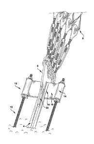
below grade installation. Here anchor 2 is a heavily weighted device,
typically concrete or
metal, which is buried below grade. While anchor 2 is typically poured
concrete, any means of
weighting and securing can be utilized and is not limited to concrete blocks
or concrete mass.
Guy anchor shaft 4 is one or more rods or shafts, usually made from metal,
which at one end
extend into anchor 2 a set distance and is typically secured by pouring
concrete around guy
anchor shaft 4, and at the other end guy anchor shaft 4 extends above grade
and is attached to
a transition device. While guy anchor shaft 4 is typically made from metal,
other options may
include, but are not limited to galvanized metal, epoxy coated metal and
concrete encased
metal. The shape of guy anchor shaft 4 may be, but is not limited to, flat
plate, round, angle,
double angle, channel, double channel or other shaped rods. The transition
device typically
being guy anchor fan plate 6 which is attached to guy anchor shaft 4 at one
end and to one or
more guy wires 8 at the other end via turnbuckles or other similar hardware.
Guy anchor fan
plate is usually made from metal. Finally, guy wire(s) 8 are one or more means
of securing the
structure which are typically metal and at one end are attached to the guy
anchor fan plate 6
and at the other end attach to the structure. Guy wire(s) 8 typically being
single strand, multi
strand or bridge strand metal based materials.
[0028] In one
embodiment the present invention details a remediation system for a guy
anchor shaft of a guyed structure or additionally guyed structure comprising
an assembly which
attaches to a guy anchor fan plate and/or the guy anchor shaft, an
anchor, one or more
remediation shafts which extend from the assembly and are secured to the
anchor, the
assembly further having one or more remediation shaft receptacles which accept
and secure
the one or more remediation shafts and a guy anchor shaft attachment able to
accept and
further secure the guy anchor shaft, the one or more remediation shaft
receptacles being
aligned in parallel or at up to a 40 degree angle with the guy anchor shaft
and the one or more
remediation shaft receptacles being affixed to the guy anchor shaft attachment
and/or the guy
anchor fan plate via a joining plate.
[0029] In
another embodiment, the present invention details a method for installing a
remediation system for a guy anchor shaft of a guyed structure or additionally
guyed structure
22580412.2 5
CA 02856775 2014-07-10
CA Application
Blakes Ref.: 11148/00001
comprising installing an assembly having one or more remediation shaft
receptacles which
accept and secure one or more remediation shafts and also having a guy anchor
shaft
attachment which accepts and further secures to a guy anchor fan plate and/or
the guy anchor
shaft, installing the one or more remediation shafts which extend from the
assembly and are
secured to an anchor, aligning the one or more remediation shaft receptacles
in parallel or at up
to a 40 degree angle with the guy anchor shaft and affixing the one or more
remediation shaft
receptacles to the guy anchor shaft attachment via a joining plate.
[0030] Figure 2 provides an above ground detail of one embodiment of the
present
invention. The following descriptions are features of a typical embodiment of
the invention,
though slight alterations are possible based on the needs of the user in a
given situation. A guy
anchor remediation assembly ("assembly") 10 which attaches to the guy anchor
shaft 4 and has
one or more remediation shafts 12 which extend from assembly 10 into the
anchor 2 at a point
other than where the guy anchor shaft attaches. Assembly 10 further attaching
to the original
guy anchor shaft 4. Assembly 10 further having one or more remediation shaft
receptacles 14
able to accept and secure one or more remediation shafts 12. Assembly 10
having a guy anchor
shaft attachment 16 able to accept and further secure guy anchor shaft 4. The
one or more
remediation shaft receptacles 14 being aligned in parallel (or at up to a 40
degree angle) with
the guy anchor shaft 4 and the one or more remediation shaft receptacles 14
being affixed to
the guy anchor shaft attachment 16 via joining plate 18. The entire assembly
typically being
made from a metal. Assembly 10 attaching to guy anchor fan plate 6 and/or guy
anchor shaft 4
either by bolting or welding. Figure 2 also detailing pinch plate 30, which
can be installed to
prevent pinching of existing rods in a scenario where joining plate 18 extends
down past the
existing fan plate connection.
[0031] Figure 3 provides another drawing of one embodiment of the present
invention
in use. In both Figures 2 and 3 the assembly being fully installed and in use
on a guyed
structure. Guy anchor shaft 4 in Figure 2 being a dual shaft and in Figure 3
being a singular
shaft. Both guy anchor shafts 4 being directly welded to guy anchor fan plate
6. Assembly 10
being either welded to guy anchor shaft 4 and/or guy anchor fan plate 6 via
normal welding
techniques or in the alternative using a bolting mechanism to adhere to same.
In one
embodiment bolting mechanism passing through assembly 10 and guy anchor fan
plate 6. In
most instances, assembly 10 resting above grade and not touching the ground
but as is seen in
Figure 3, optionally assembly 10 may come into contact with the ground.
Keeping the assembly
22580412.2 6
CA 02856775 2014-07-10
CA Application
Blakes Ref.: 11148/00001
off of and not in contact with the soil/ground allowing for better protection
from corrosion. In
addition, keeping a slight angle to the assembly allowing rain water and other
contaminant to
drain away from assembly 10.
[0032] Figure 4 is a drawing of one embodiment of the present invention
which
includes cathodic protection. Cathode testing head 20 is attached to assembly
10. One or
more wires 22 attach from cathode testing head 20 to anodes and reference
cells to lessen the
environmental effects on the shafts. In one embodiment wire 22 attaching to
anode bags which
are located below grade. Anode bags being made from or containing more
desirable materials
for corrosion than the steel/metal of the apparatus. Alternatively wire
extension 28 coming from
the base of the testing head and leading to a reference cell below grade. Here
a voltage test
can be run to show the cell deterioration and the need for replacement of the
anode bags.
Figure 4 also provides an embodiment where four remediation shafts 12 are
utilized. Typically
two remediation shafts are used, but customization to 1, 2, 3, 4, 5 or more
remediation shafts
are possible.
[0033] Figure 5 is a drawing of an embodiment where remediation shafts 12
are
attached to the original anchor 2. After attachment, the volume surrounding
remediation shafts
12 is filled with concrete 24 to provide additional environmental protection
and delay decay of
the shafts. The filler used around remediation shafts 12 can be dirt, concrete
(to encapsulate
the rods), or stone/gravel to allow for drainage. Each type of fill depending
on the climate and
needs of the individual user. Another means of protecting remediation rods 12
involves coating
with an epoxy or other material to prolong their lifespan.
[0034] Figures 6 and 7 are drawings detailing the installation of assembly
10 and
remediation rods 12. During installation, the area surrounding guy anchor
shaft 4 down to
anchor 2 is removed to have access to both. In this example, two attachment
points would be
made in anchor 2. Typically this involves drilling of two holes for insertion
of remediation rods 12
into anchor 2. Remediation rods 12 can be inserted via a screw-in mechanism or
can be
inserted into a previously created void and then held in place with an epoxy
or resin. Alternative
means of securing remediation rods 12 into anchor 2 include, but are not
limited to, concrete,
resins, epoxies, polyurethane based products, polysulfide based products,
bisphenol based
epoxies, cured epoxy resins, or any other means which helps secure the two
items. Other
means of securing remediation rods 12 into anchor 2 include mechanical
expansion bolts,
through bolts or any means where the rod is inserted and allows for expansion
of the inserted
22580412.2 7
CA 02856775 2014-07-10
CA Application
Blakes Ref.: 11148/00001
end via pressure or torque. Remediation rods 12 are attached to assembly 10 at
the one or
more remediation shaft receptacles 14. Assembly can then be welded or bolted
to guy anchor
shaft 4 at guy anchor shaft attachment 16. Assembly can also be welded or
attached to guy
anchor shaft attachment 16 as needed. Once remediation rods are secured and
tightened to
the torque or stress desired, the area around the guy anchor shaft 4 is
replaced (filled back in).
Figure 7 also detailing coupling nut 32 which is used to extend the length of
remediation rods
12.
[0035] Figures 8, 9 and 10 are drawings for one embodiment of the present
invention
where the assembly is a bolt-on assembly 40. Here bolt-on assembly 40 attaches
to guy
anchor fan plate 6 via a series of nuts, bolts 48 or some sort of fastener(s).
In one embodiment
bolt-on assembly 40 attaching thru holes (either drilled or previous existing)
in guy anchor fan
plate 6. The means of securing one or more remediation shafts 12 being shaft
securing means
26 which can be a hex bolt, a square bolt or any other suitable fastening
means. Here one or
more remediation shafts 12 attaching to or protruding thru bolt-on assembly in
the bolt
remediation assembly portion 46. Bolt remediation assembly portion 46 having
one or more
attachment points and/or holes for attachment or corresponding remediation
shaft(s) 12. Figure
9 showing a bolt-on assembly 40 for using two remediation shafts 12 and Figure
10 showing a
bolt-on assembly 40 for using four remediation shafts 12.
[0036] Figures 11, 12 and 13 are drawings for another embodiment of the
present
invention where the assembly is a welded assembly 60. Here welded assembly 60
is attached
or secured to guy anchor fan plate 6 via a weld or similar attaching means. In
one embodiment
welded assembly 60 being secured to guy anchor fan plate 6 and further
containing one or more
remediation shaft receptacles 14. Remediation shaft receptacles 14 being able
to receive
remediation shaft 12 and secure using shaft securing means 26 such as a hex
bolt, a square
bolt or any other suitable fastening means. Figure 12 showing a welded
assembly 60 for using
two remediation shafts 12 with two original anchor shafts 4 and Figure 10
showing a welded
assembly 60 for using two remediation shafts 12 with one original anchor shaft
4.
[0037] Figures 14 and 15 drawings for another embodiment of the present
invention
where the assembly is a welded assembly 60. Here welded assembly 60 is
attached or secured
to guy anchor fan plate 6 via a weld or similar attaching means. In one
embodiment welded
assembly 60 being secured to guy anchor fan plate 6 and further containing, in
this
embodiment, at least 4 remediation shaft receptacles 14. Remediation shaft
receptacles 14
22580412.2 8
CA 02856775 2014-07-10
CA Application
Blakes Ref. 11148/00001
being able to receive remediation shaft 12 and secure using shaft securing
means 26 such as a
hex bolt, a square bolt or any other suitable fastening means. Figure 14
showing a welded
assembly 60 for using four remediation shafts 12 with two original anchor
shafts 4 and Figure 10
showing a welded assembly 60 for using four remediation shafts 12 with one
original anchor
shaft 4.
[0038] Care must be taken to properly size assembly 10 and remediation
shafts 12 to
ensure they can adequately handle the stresses and torques in the event guy
anchor shaft 4
fails. In the examples shown in Figures 1 though 9, assembly 10 being from 8"
to 48" in width
across assembly from remediation shaft receptacle to receptacle. Both smaller
and larger sizes
being possible and covered herein based on an individual user needs.
[0039] While metal is preferred due to strength and longevity, other
materials can be
utilized for any or all of the components of the present invention. Such
materials include, but
are not limited to: plastics, metal alloys, and carbon fiber. In one
embodiment each component
preferring a different metal, such as plate being ASTM A572, pipe being ASTM
A53-B, rods
being ASTM F1554 or ASTM 722, nuts being ASTM A194 and washers being ASTM
F436.
These ASTM references being preferred but not limiting as any suitable
arrangement is
possible.
[0040] In one embodiment the anchor shaft being a solid cylindrical rod,
Other
embodiments including, but not limited to angled rods, channel rods and flat
plate rods.
[0041] In one embodiment the anchor used by the remediation shafts being
the
original anchor used on the original system. In another embodiment, one or
more additional
anchors being used.
[0042] While the typical arrangement for remediation shafts 12 is one on
each side of
guy anchor shaft 4 (or planar setup), virtually any setup is possible
including two, three or more
per side, a cross pattern for 4 remediation shafts, or any other suitable
arrangement. Typically
symmetrical setups allowing for better placement of moment forces along a
design system.
[0043] The standard means for securing remediation shafts 12 is via a
shaft securing
means 26. The typical shaft securing means 26 being a hex nut. Alternatively,
this could be
any number of apparatus or fastening means which locks remediation shaft 12 in
place such as
but not limited to a cotter pin, a square nut, cap or a direct weld.
22580412.2 9
CA 02856775 2014-07-10
CA Applcation
Blakes Ref.: 11148/00001
[0044] The guy
anchor remediation system disclosed herein provides a safer, less
costly and permanent solution to corroding guy anchors than the conventional
method of
replacement. Upon completion, it results in no additional disturbance to the
environment than
the impact it had prior to the remediation. Furthermore there is no need to
relocate guy wires to
other anchor heads, which could possibly place undue stress or torque no the
structure. In
addition the guy anchor remediation system can strengthen existing anchor
shafts found to be
under-designed or require a size increase due to loading above the original
design load.
[0045] It will
be apparent to those skilled in the art that various modifications and
variations can be made to the present disclosure without departing from the
spirit and scope of
the disclosure. Thus, it
is intended that the present disclosure cover all conceivable
modifications and variations of this disclosure, provided those alternative
embodiments come
within the scope of the appended claims and their equivalents. The various
embodiments of the
present invention described above may be combined together in any number
and/or
combination.
22580412.2 10