Note: Descriptions are shown in the official language in which they were submitted.
CA 02856971 2014-07-15
STRUCTURAL CONNECTORS FOR DRAGLINE BOOM AND MAST TUBULAR
CLUSTERS AND METHODS FOR REPAIR, REINFORCEMENT AND LIFE
EXTENSION OF DRAGLINE BOOMS AND MASTS
Technical Field
[0001] This invention relates to heavy equipment. The invention has particular
application to draglines and other equipment having extended booms with
tubular chords
or lacings. The invention may be used to repair old booms or in the
manufacture of new
booms.
Background
[0002] Dragline excavators have long booms which comprise a number of main
tubular
chords connected by tubular lacing. The tubular lacing is connected to the
main chords at
cluster joints. Figure 1 illustrates a typical cluster joint and the complex
intersection
between the lacings and the chord. Dragline booms are called upon to support
large
dynamic loads. Stresses tend to be concentrated at the cluster joint weldments
at which
the lacing is connected to the main chord. Over time, these stresses cause
fatigue failures
at the cluster joints. With increased productivity demands and cost of machine
down time,
failure of cluster joints on the current tubular dragline boom design requires
temporary
weld repair until a sufficiently long outage is available to lower the boom
and complete a
repair under controlled conditions. Such temporary weld repair may be
performed under
adverse conditions. Even under controlled conditions with the boom lowered,
the fatigue
life of the repaired cluster joint is undesirably short.
[0003] Aside from the limited maintenance schedules which generally preclude
lowering
the boom and the outage cost associated with such an operation, lowering the
boom is
viewed by operators as a dangerous exercise exposing the operator to a
potentially high
risk event with significant financial consequences.
[0004] Conventional tubular boom structures typically have about 10% of the
welds
hidden from view by the overlapping nature of the cluster joint design. This
makes
CA 02856971 2014-07-15
2
routine inspection impossible. Even locating cracks by pressurizing chords of
the boom
and finding air leaks can be difficult.
[0005] Numerous failures of cluster joints on tubular booms have occurred
throughout the
world, some leading to catastrophic collapse of the boom.
[0006] Failures of cluster joints may be initiated by the growth of fatigue
cracks at welds
connecting the secondary lacings and the main chord. These regions are
associated with
high stress concentrations arising from the cluster geometry as well as the
presence of
weld beads. Where clusters have been weld repaired in situ, the fatigue life
of the joint
can be reduced due to incomplete penetration of the weld, inclusion of
contaminants,
irregular internal and external weld geometry and the generation of high
residual stresses
due to the welding process. If a failure at a cluster involves the main chord
material it can
be necessary to cut a window to gain access to the main chord and allow for
repair of the
chord through the window. After the repair is completed the window must be re-
inserted
and welded in place. This repair is difficult to conduct and causes damage to
the cluster as
a consequence of the constraints of the repair i.e. weld profile grinding or
post weld
dressing techniques are difficult to apply.
[0007] There is a need for dragline booms that have increased service lives.
There is also
a need for methods for repairing failures or defects in dragline booms in situ
or when the
boom is lowered, which avoid at least some of the disadvantages of current
methods.
Brief Description of the Drawings
[0008] Exemplary embodiments are illustrated in referenced figures of the
drawings. It is
intended that the embodiments and figures disclosed herein are to be
considered
illustrative rather than restrictive.
[0009] Figure 1 is a drawing of a typical cluster arrangement applied on a
tubular dragline
boom, for example BucyrusTM type dragline booms.
CA 02856971 2014-07-15
3
[0010] Figure 2 is a cross section view showing the complex weld geometry
arising at the
lacing/chord intersection/interface.
[0011] Figures 3A, 3B and 3C make up a set of drawings of a curved spade weld-
on
connector installed in a boom cluster. Various views of the cluster are
illustrated.
Figures. 3A to 3C also illustrate the curved spade connector using plugs
inserted into the
lacing or sleeves which receive ends of the lacing to allow for axial and
rotational
alignment between the curved spade plate and the lacing.
[0012] Figures 4A and 4B are schematic drawings showing example dimensional
relationships between dimensions of the cluster joint. Optimum dimensions for
specific
applications may be determined using FEA (finite element analysis).
[0013] Figures 5A, 5B and 5C illustrate typical connector details.
[0014] Figure 6 illustrates example connector weldment details.
[0015] Figure 7 illustrates regions for post weld dressing.
[0016] Figures 8A and 8B illustrates alternative embodiments which incorporate
flat plate
connectors.
=
Description
[00171 Throughout the following description specific details are set forth in
order to
provide a more thorough understanding to persons skilled in the art. However,
well
known elements may not have been shown or described in detail to avoid
unnecessarily
obscuring the disclosure. Accordingly, the description and drawings are to be
regarded in
an illustrative, rather than a restrictive, sense.
[0018] This invention relates to a construction for dragline booms and similar
boom
structures. The construction may be applied to newly fabricated booms and also
has
application in repairing existing booms. The construction may be retrofitted
to existing
CA 02856971 2014-07-15
4
booms. The construction comprises a curved spade plate that provides an
interface
between a main chord of a boom and tubular lacing at a cluster joint. The
curved spade
plate connector can be accurately manufactured to match the cluster geometry.
Use of the
curved spade connector thereby avoids the need for complex three-dimensional
weld
geometry where the lacings come together with the chord. In some embodiments,
the
curved spade plate is connected to the tubular lacing members with plugs that
fit into the
tubular lacing members and can be rotated to provide axial and rotational
alignment to
corresponding connection features on the curved spade plate before they are
welded in
place.
[0019] A method for repairing a boom using a spade plate connector as
described herein
advantageously permits cutting away the lacings from the chord, thereby
providing access
to remove damaged or previously-repaired material. The exposed chord can be
inspected
and fully weld repaired before installing the spade plate. The method may be
applied to a
tubular dragline boom, for example to a BucyrusTM type boom with tubular
cluster joints,
and presents a new method for repairing these clusters in a manner that can be
performed
efficiently and that can provide significantly improved fatigue life as
compared to
currently-used repair techniques. In some embodiments the method involves
inserting
plugs into ends of the cut-off lacing members, adjusting rotations and/or
extensions of the
plugs to align connecting features on the plugs with corresponding connecting
features on
the curved spade plate and then welding the plugs to the lacing members and to
the curved
spade plate. The curved spade plate is also welded to the main chord of the
boom to
provide a connection between the main chord and the lacing members.
[0020] One aspect of the invention provides a curved spade joint connector
that has
application in tubular dragline booms, for example on BucyrusTM draglines. The
cluster
joints may be installed in situ without requiring lowering of the boom if
adequate jigging
is engineered to support the joint in this condition. Connectors as described
herein may be
installed during manufacture of a boom or installed during a repair, either in
situ, or with
the boom lowered.
CA 02856971 2014-07-15
[0021] Another aspect of the invention provides a boom, for example a dragline
boom,
comprising a cluster joint made with a spade connector as described herein.
The boom
may have a plurality of main chords. Lacing members may extend between spade
connectors on different ones of the main chords. In some embodiments, the boom
comprises a plurality of tubular main chords each having a plurality of
cluster joints
spaced apart along it. Each of the cluster joints comprises one or more spade
connectors
as described herein. Lacing members extend between the spade connectors on
different
ones of the main chords.
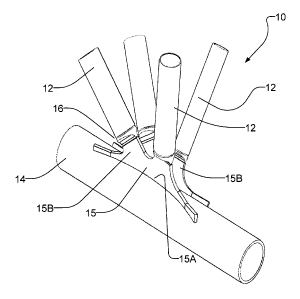
[0022] Figures 3A to 3C show an example cluster joint 10 in a boom. Cluster
joint 10
connects tubular lacing members 12 to main chord 14. Cluster joint 10
comprises spade
plates 15. Each spade plate 15 has a curved elongated edge 15A connected to
main chord
14 and projecting tabs 15B to which lacing members 12 may be coupled.
[0023] In the illustrated embodiment, lacing members 12 are coupled to spade
plates 15
by way of coupling members 16 that are initially (until welded in place)
rotatable and
axially extendable relative to lacing members 12. Coupling members 16 may, for
example, comprise plugs insertable into the bores of lacing members 12.
Coupling
members 16 may comprise slots dimensioned to receive tabs 15B. In some
alternative
embodiments, coupling members 16 comprise sleeves having inner diameters
dimensioned
to receive lacing members 12.
[0024] Cluster joint 10 has a number of advantages over prior art cluster
joints as
illustrated, for example in Figures 1 and 2. The curved spade plate design
strengthens the
chord in the circumferential direction, avoiding high localized stresses. This
improves the
fatigue life of the cluster joint. The weld between curved spade connector 15
and main
chord 14 lies generally along the axis of main chord 14. The weld location is
easily
accessible to facilitate high quality full penetration welds. Since the weld
holding curved
spade plate 15 to main chord 14 extends predominantly parallel rather than
transverse to
the stress in the chord, which facilitates a longer fatigue life of the weld.
CA 02856971 2014-07-15
6
[0025] Figures 4A and 4B show example dimensional relationships between
dimensions
of a typical cluster joint. These dimensional relationships are generic rules
based on
research conducted to date. An optimal design for a specific application may
be generated
by modelling the specific cluster joint under consideration and applying tools
such as
finite element analysis to generate a configuration that provides required
strength while
reducing stresses under expected operating conditions to an acceptable level.
[0026] As illustrated in Figure 4A, in some preferred embodiments 1 < H/d < 2
where d is
the lacing diameter and H is the height of the spade plate as measured from
the main
chord. In some preferred embodiments 20 < cp, <45 where cp, as shown, is the
angle
subtended on main chord 14 as a result of the curvature of curved spade plate
15. As
shown in Figure 4B, in some preferred embodiments 2 < L/w < 5 where L is the
length of
spade plate 15 measured along the longitudinal axis of main chord 14 and w is
the length
measured along the longitudinal axis of main chord 14 of the projections onto
the main
chord of the lacing members connected to spade plate 15.
[0027] Figures 5A to 5C show application of a spade plate connector designated
generally
by the reference 15. Connector 15 may be cast or forged or cut or milled from
rolled
plate, for example. Plugs 16 are inserted into lacing members 12 and allow for
axial and
rotational alignment to connector 15 prior to being welded in place. In some
embodiments
a plug 16 comprises a portion dimensioned to be received within a bore of a
lacing
member12 and a flange which can bear against an end of the lacing member 12.
The plug
16 may be fastened to the lacing member 12 with a circumferential weld.
[0028] The curved plate geometry of connector 15 facilitates self-alignment of
connector
15 to the axis of the main chord 14. Geometric details 27 (see Figure 6) may
be applied to
connector 15 to reduce potential stress concentration effects at one or both
ends of the side
15A of curved spade connector 15 that is joined to main chord 14. The actual
geometry of
connector 15 will vary according to the cluster geometry (e.g. the angles at
which lacing
members 12 approach main chord 14, the diameters of lacing members 12, the
diameter of
main chord 14 etc.).
CA 02856971 2014-07-15
7
[0029] Where a cluster joint uses two spade plates (as shown for example in
Figure 5B)
convex sides of the spade places may face one another. Where a cluster joint
uses two
spade plates the spade plates may be constructed do that their ends are
staggered along the
length of main chord 14.
[0030] Connector 15 may be prepared for welding attachment to main chord 14 by
bevelling or chamfering edge 15A to facilitate attachment to main chord 14
with a full
penetration weld.
[0031] Figure 7 illustrates post weld methods that may be applied for
improving the life
span of a cluster joint 10. Weld 25 may be re-enforced and profile ground.
After
profiling, shot or ultrasonic peening may be applied as a post weld treatment
to improve
the fatigue life of weld 25. Nose detail 28 may be trimmed and profile ground
to reflect
the profiling of weld 25 at end 27.
[0032] In the illustrated embodiments, connector 15 is aligned along the axis
of the
primary member or chord 14. This reduces the exposure of weld transverse to
the
longitudinal axis of the primary member thereby increasing the fatigue life of
connector
weld 25.
[0033] A connector 10 may be installed at a cluster joint of a dragline boom
by cutting out
sections of the lacing members 12 that meet at the cluster joint. The primary
member (e.g.
main chord 14) can then be weld repaired to a high quality since there is
ample access to
the location at which the lacing members were formerly attached to the primary
member.
Each lacing member is cut back to the correct length to so that the plug 16
can mate with
the appropriate tab of curved spade plate connector 15. Connector 15 is then
positioned
on the main chord 14 of the boom. At a suitable point after the spade
connector 15 has
been positioned on the main chord so that-it aligns with the plugs 16,
connector 15 is
welded to main chord 14. Then the secondary lacing members 12 are connected to
the
spade plate connector 15 by welding plugs 16 onto lacing members 12 and by
welding
plugs 16 to connector 15. After welding, the welds may be profile ground to
further
reduce stress concentration effects associated with the weld profile. Further
post-weld
CA 02856971 2014-07-15
8
dressing such as shot or ultrasonic peening may be applied to improve the life
of the
repaired material by inducing a surface layer of residual compressive stress.
[0034] Although the present invention has been described with reference to the
illustrated
embodiments thereof, it should be understood that numerous other modifications
and
embodiments can be devised by those skilled in the art that will fall within
the spirit and
scope of the principles of this invention. For example, the features described
herein and/or
shown in the accompanying drawings may be combined in any suitable
combinations or
sub-combinations including those that are described herein. Further, the
embodiments and
features may be modified and/or added to ways that would be inferred by those
skilled in
the art from this description and/or the accompanying drawings.
[0035] For example Figure 8A shows an alternative embodiment with a planar
spade
connector and machined slots cut in the connector to receive the lacings. An
alternative
with machined plugs or adjustable inserts to improve the transition between
the lacing and
spade connector is illustrated in Figure 8B.
[0036] In other non-preferred alternative embodiments, connector plates may
have the
form of flat plates bent along one or more discrete bend lines to provide a
concave face
and a convex face as opposed to being continuously curved as illustrated, for
example, in
Figures 5A to 5C. Such connector plates may have discrete flat planes
separated by bend
regions to construct an effective plate curvature.
[0037] An advantage of the embodiments illustrated in the drawings is that,
after repair,
main chord 14 is exposed (where it was previously covered by the cluster
joint) and
therefore easily accessed for inspection and any necessary future repairs.