Note: Descriptions are shown in the official language in which they were submitted.
CA 02857122 2014-05-27
METHOD OF SEPARATING CARBON DIOXIDE
FROM LIQUID ACID GAS STREAMS
FIELD OF THE INVENTION
[0001] The present application is directed to the separation of carbon
dioxide from a
liquid acid gas stream, wherein the liquid acid gas stream is composed
primarily of hydrogen
sulphide and carbon dioxide.
BACKGROUND
[0002] Natural gas reservoirs may often contain high levels of acid
gases, such as CO2
and H2S. In these cases, a cryogenic process may provide an efficacious way to
separate the
acid gases from the methane. The cryogenic process could include a simple bulk
fractionation, a Ryan-Holmes process, or a more complex cryogenic
fractionation process.
The cryogenic processes separate methane from CO2 and FI2S by condensation and
fractionation, and can produce the acid gas in a liquid phase for efficient
disposal via
pumping. However, in the cryogenic processes the H2S- is separated with the
CO2 in a single
liquid acid gas stream. Often, the acid gas will be immediately reinjected for
disposal, where
the mixture will not cause any problems.
100031 However, the CO2 may be reused or sold for example, for enhanced
oil recovery
(E0R) or other purposes, if the H2S and other sulfur compounds can be removed.
When CO2
and H2S are mixed, they form a mixture that is difficult to separate.
Separating 1-12S and CO2
usually involVes vaporizing the entire acid gas stream and using selective
chemical or
physical solvents for separation. This increases the disposal cost of the
residual, often sulfur
containing, acid gas stream, since it is no longer in the liquid phase and
requires compression
instead of pumping.
[0004] Fig. I is a temperature - composition phase plot 100 showing the
equilibrium
concentrations of CO2 in a mixture with H2S at 100 psia. The x-axis 102
indicates the mole
fraction of CO2, while the y-axis 104 represents the temperature in 'I' ( C).
The concentration
- -
CA 02857122 2014-05-27
of the CO2 in the vapor phase 106 approaches the concentration of the CO2 in
the liquid phase
108 at >90% CO2.
[00051 Fig. 2 is a temperature - composition phase plot 200 showing the
equilibrium
concentrations of CO2 in a mixture with H2S at 600 psia. Like numbered items
are as
described with respect to Fig. 1. As this plot 200 shows, the concentrations
in the vapor
phase 106 and liquid phase 108 are closer at higher pressures. As these plots
100 and 200
indicate, complete separation by fractionation cannot be achieved without some
additional
separation processes. Pure 112S could be produced by fractionation, but pure
CO2 would be
impractical, or even infeasible.
100061 Although fractionation may not be used for complete separation of
CO2,
commercial techniques due exist for separating clean CO2 from a CO2/H2S
mixture, For
example, selective amine solvent absorption, such as by MDEA or Flexsorb/Sli,
can be used
to absorb H2S from a vapor acid gas stream, producing a pure CO2 vapor stream,
and an
H2S/CO2 mixed vapor stream. In another example, some physical solvents, such
as Selexol,
have selectivity's, or K-Values, that allow the separation of H2S and CO2 when
the solvent is
present. Other methods, using gas permeation membranes or molecular sieves,
could be used
in conjunction with fractionation or solvents to achieve H28 and CO2
separation.
[0007] In one example, U.S. Patent No. 5,335,504 to Darr, et al.,
discloses a process for
recovering carbon dioxide from a natural gas stream. The process may be used
to recover
CO2 that has been injected for enhanced oil recovery. The process is based on
a cryogenic
distillation column, but does not discuss. the separation of CO2 from a
mixture with H2S.
[0008] Further, U.S. Patent No. 4,318,723 to Holmes discloses a cryogenic
distillative
separation of acid gases from methane, hereinafter termed the "Ryan-Holmes
Process." The
Ryan-Holmes Process is a method of eliminating solids formation during a
cryogenic
distillative separation of acid gases from methane. The method includes adding
an agent to
control solids formation to a zone of a distillation column at which solids
formation may
occur. Typical agents are C2 -05 a]kanes or other nonpolar liquids which are
miscible with
methane at the column conditions. Preventing the formation of solids permits a
more
- 2 -
CA 02857122 2014-05-27
complete separation to be achieved. The Ryan-Holmes Process can generate a
liquid acid gas
stream, but does not discuss separating CO2 from a mixture with H2S,
[OM] Another technique for cryogenic purification of natural gas is
provided in
International Patent Application Publication No. WO/2008/091316, which
discloses a
controlled freeze zone tower. The controlled freeze zone tower is a cryogenic
distillation
tower which allows for the separation of a fluid stream containing at least
methane and carbon
dioxide. The cryogenic distillation tower has a lower stripping section, an
upper rectification
section, and an intermediate spray section. The intermediate spray section
includes a plurality
of spray nozzles that inject a liquid freeze zone stream. The nozzles are
configured such that
substantial liquid coverage is provided across the inner diameter of the
intermediate spray
section. The liquid freeze zone stream generally includes methane at a
temperature and
pressure whereby both solid carbon dioxide particles and a methane-enriched
vapor stream
are formed. The tower may further include one or more baffles below the
nozzles to create
frictional resistance to the gravitational flow of the liquid heeze zone
stream, This aids in the
breakout and recovery of methane gas, Additional internal components are
provided to
improve heat transfer and to facilitate the breakout of methane gas. As for
the Ryan Holmes
Process, the controlled freeze zone tower can generate a liquid acid gas
stream, hut does not
discuss separating CO2 from a mixture with 112S.
[00101 In addition to the newer cryogenic techniques, numerous techniques
have
traditionally been used to prepare natural gas for marketing to customers.
Collectively, these
techniques are referred to herein as "warm gas processing." In warm gas
processing, the raw
gas is processed to remove acid gases, such as hydrogen sulfide and carbon
dioxide. This was
historically performed by amine treatment, in which an amine reacts with the
acid gas. When
exhausted, the amine may be regenerated to remove the acid gas. More recently,
newer
technology has been developed, based on the use of polymeric membranes to
separate carbon
dioxide and hydrogen sulfide from a natural gas stream,
[00111 The acid gases can then be routed into a sulfur recovery unit
which converts the
hydrogen sulfide in the acid gas into sulfur products, such as elemental
sulfur or sulfuric acid.
After removal of the acid gases, water vapor can be removed, using any number
of methods.
- 3 -
CA 02857122 2014-05-27
[00121 Other components may be removed from the remaining product, such
as mercury,
and natural gas liquids. This produces a gas that may have methane blended
with a number of
inert and hydrocarbon components, including nitrogen and helium, among others.
Higher
carbon number components, such as ethane and heavier hydrocarbons, may be
removed and
marketed separately as natural gas liquids (NGL), liquid propane gas (LPG),
and the like,
[00131 All of these methods for isolating CO2 from a CO2/H2S mixture have
the same
drawback in that the acid gas stream must be fully vaporized, since the
separation occurs in
the vapor phase. Further all of the products are produced as vapor streams.
Since liquid acid
gas is easier to dispose of (less energy via pumping rather than compression)
and the acid gas
is available in the liquid phase when cryogenic separation processes are used,
it would be
useful for one or both of the products to be produced as liquids. For example,
it would be
useful for a waste injection stream, usually containing H2S, to be a liquid
stream, since that
stream would normally require a higher final pressure than a clean, product
CO2 stream.
Thus, there is a need for a process to separate clean CO, from mixed 1-
12S/CO2, liquid acid gas
streams, while maintaining the residual acid gas in the liquid phase for easy
disposal.
SUMMARY
[0014] An embodiment described herein provides a method for generating a
CO2 product
stream. The method includes generating a liquid acid gas stream comprising H2S
and CO2.
The liquid acid gas stream is flashed to form a first vapor stream and a
bottom stream. The
bottom stream is fractionated to form a second vapor stream and a liquid acid
waste stream.
The first vapor stream and the second vapor stream are combined to form a
combined vapor
stream and the combined vapor stream is treated with a physical solvent to
remove excess
H2S, forming the CO2 product stream.
[0015] Another embodiment provides a system for generating a CO2 enriched
stream.
The system includes an acid gas flash drum configured to flash a portion of a
liquid acid gas
stream into a vapor stream and a liquid stream. A bulk liquid stripper is
configured to contact
the liquid stream with an acid gas stream and flash at least a portion of the
liquid stream into
an overhead stream and a bottoms stream, wherein the overhead stream and the
vapor stream
are mixed to form a combined gas stream, and the bottoms stream is disposed of
as a
- 4 -
CA 02857122 2014-05-27
concentrated acid gas stream. An absorption column is configured to contact
the combined
gas stream with a preloaded absorbent stream, wherein a rich absorbent stream
exits the
bottom of the absorption column and a CO2 enriched vapor stream exits the top
of the column.
100161 Another embodiment provides a method for purifying a natural gas
stream. The
method includes dehydrating the natural gas stream and cryogenically
separating the natural
gas stream into a methane rich fraction, a natural gas liquids fraction, and a
liquid acid gas
stream. The liquid acid gas stream is fractionated to form a CO2 enriched
stream and a liquid
acid waste stream. The CO2 enriched stream is treated with an absorbent to
remove excess
H2S forming a CO2 product stream.
BRIEF DESCRIPTION OF THE DRAWINGS
10017] The advantages of the present techniques are better understood by
referring to the
following detailed description and the attached drawings, in which:
100181 Fig. I is a temperature - composition phase plot showing the
equilibrium
concentrations of CO2 in a mixture with H2S at 100 psia;
[0019] Fig. 2 is a temperature - composition phase plot showing the
equilibrium
concentrations of CO2 in a mixture with H2S at 600 psia;
[0020] Fig. 3 is a block diagram of a system that can be used to isolate
a CO2 product
stream as part of a natural gas purification process;
[0021] Fig. 4 is a simplified process flow diagram of a cryogenic
separation system that
can be used to generate a liquid acid gas stream;
[0022] Fig. 5 is a simplified process flow diagram of a CO2 separation
process that
separates a liquid acid gas stream into a CO2 product stream and a liquid acid
gas waste
stream;
[0023] Fig. 6 is a simplified process diagram of an absorbent
regeneration system that
removes acid gases from a physical solvent from Fig. 5 and returns a lean
absorbent stream to
the absorbent column shown in Fig. 5; and
- 5 -
CA 02857122 2014-05-27
[0024] Fig. 7 is a block diagram of a method for generating a CO2 product
stream and a
liquid acid gas waste stream using a combined system.
DETAILED DESCRIPTION
100251 In the following detailed description section, specific
embodiments of the present
techniques are described. However, to the extent that the following
description is specific to a
particular embodiment or a particular use of the present techniques, this is
intended to be for
exemplary purposes only and simply provides a description of the exemplary
embodiments.
Accordingly, the techniques are not limited to the specific embodiments
described below, but
rather, include all alternatives, modifications, and equivalents falling
within the true spirit and
scope of the appended claims.
100261 At the outset, for ease of reference, certain terms used in this
application and their
meanings as used in this context are set forth. To the extent a term used
herein is not defined
below, it should be given the broadest definition persons in the pertinent art
have given that
term as reflected in at least one printed publication or issued patent.
Further, the present
techniques are not limited by the usage of the terms shown below, as all
equivalents,
synonyms, new developments, and terms or techniques that serve the same or a
similar
purpose are considered to be within the scope of the present claims.
[0027] "Acid gases" are contaminants that are often encountered in
natural gas streams.
Typically, these gases include carbon dioxide (CO2) and hydrogen sulfide
(H2S), although any
number of other contaminants may also form acids. Acid gases are commonly
removed by
contacting the gas stream with an absorbent, such as an amine, which may react
with the acid
gas. When the absorbent becomes acid-gas "rich," a desorption step can be used
to separate
the acid gases from the absorbent. The "lean" absorbent is then typically
recycled for further
absorption. As used herein a "liquid acid gas stream" is a stream of acid
gases that are
condensed into the liquid phase, for example, including CO2 dissolved in H2S
and vice-versa.
10028] The Claus process is a process discovered over 120 years ago that
has been used
by the natural gas and refinery industries to recover elemental sulfur from
hydrogen sulfide-
containing gas streams. Briefly, the Claus process for producing elemental
sulfur comprises
two major sections. The first section is a thermal section where 1-128 is
converted to elemental
- 6 -
CA 02857122 2014-05-27
sulfur at approximately 1,800-2,200 'F. No catalyst is present in the thermal
section. The
second section is a catalytic section where elemental sulfur is produced at
temperatures
between 400-650 F over a suitable catalyst (such as alumina). The reaction to
produce
elemental sulfur is an equilibrium reaction and, hence, there are several
stages in the Claus
process where separations are made in an effort to enhance the overall
conversion of H2S to
elemental sulfur. Each stage involves heating, reacting, cooling and
separation.
10029] As used herein, a "column" is a separation vessel in which a
counter current flow
is used to isolate materials on the basis of differing properties. In an
absorbent column, a
physical solvent is injected into the top, while a mixture of gases to be
separated is flowed
through the bottom. As the gases flow upwards through the filling stream of
absorbent, one
gas species is preferentially absorbed, lowering its concentration in the
vapor stream exiting
the top of the column. In a fractionation column, liquid and vapor phases are
counter-
currently contacted to effect separation of a fluid mixture based on boiling
points or vapor
pressure differences, The high vapor pressure, or lower boiling, component
will tend to
concentrate in the vapor phase whereas the low vapor pressure, or higher
boiling, component
will tend to concentrate in the liquid phase. Cryogenic separation is a
separation process
carried out in a column at least in part at temperatures at or below 150
degrees Kelvin (K).
To enhance the separation, both types of columns may use a series of
vertically spaced trays
or plates mounted within the column and/or packing elements such as structured
or random
packing. Columns may often have a recirculated stream at the base to provide
heat energy for
boiling the fluids, called reboiling. In a fractionation column, a portion of
the overhead vapor
may be condensed and pumped back into the top of the column as a reflux
stream, which can
be used to enhance the separation and purity of the overhead product. A bulk
liquid stripper
is related to a fractionation column. However, the bulk liquid stripper
functions without the
use of a reflux stream and, thus, cannot produce a high-purity overhead
product.
100301 "Cold box" refers to an insulated enclosure which encompasses sets
of process
equipment such as heat exchangers, columns, and phase separators. Such sets of
process
equipment may form the whole or part of a given process.
- 7 -
CA 02857122 2014-05-27
100311 "Compressor" refers to a device for compressing a working gas,
including gas-
vapor mixtures or exhaust gases. Compressors can include pumps, compressor
turbines,
reciprocating compressors, piston compressors, rotary vane or screw
compressors, and
devices and combinations capable of compressing a working gas.
[00321 "Cryogenic distillation" has been used to separate carbon dioxide
from methane
since the relative volatility between methane and carbon dioxide is reasonably
high. The
overhead vapor is enriched with methane and the bottoms product is enriched
with carbon
dioxide and other heavier hydrocarbons. Cryogenic distillation processing
requires the proper
combination of pressure and temperature to achieve the desired product
recovery.
[0033] The term "gas" is used interchangeably with "vapor," and means a
substance or
mixture of substances in the gaseous state as distinguished from the liquid or
solid state.
Likewise, the term "liquid" means a substance or mixture of substances in the
liquid state as
distinguished from the gas or solid state.
100341 "Heat exchanger" refers to any equipment arrangement adapted to
allow the
passage of heat energy from one or more streams to other streams. The heat
exchange may be
either direct (e.g., with the streams in direct contact) or indirect (e.g.
with the streams
separated by a mechanical barrier). The streams exchanging heat energy may be
one or more
lines of refrigerant, heating or cooling utilities, one or more feed streams,
or one or more
product streams. Examples include a shell-and-tube heat exchanger, a cryogenic
spool-wound
heat exchanger, or a brazed aluminum-plate fin type, among others.
[9035] A "hydrocarbon" is an organic compound that primarily includes the
elements
hydrogen and carbon, although nitrogen, sulfur, oxygen, metals, or any number
of other
elements may be present in small amounts. As used herein, hydrocarbons
generally refer to
organic materials that are harvested from hydrocarbon containing sub-surface
rock layers,
termed reservoirs. For example, natural gas is normally composed primarily of
the
hydrocarbon methane.
[0036] The term "natural gas" refers to a multi-component gas obtained
from a crude oil
well (associated gas) or from a subterranean gas-bearing formation (non-
associated gas). The
composition and pressure of natural gas can vary significantly. A typical
natural gas stream
- 8 -
CA 02857122 2014-05-27
contains methane (C1) as a significant component. Raw natural gas will also
typically contain
ethane (C2), higher molecular weight hydrocarbons, one or more acid gases
(such as carbon
dioxide, hydrogen sulfide, carbonyl sulfide, carbon disulfide, and
mercaptans), and minor
amounts of contaminants such as water, helium, nitrogen, iron sulfide, wax,
and crude oil.
100371 Low-BTU natural gas indicates a natural gas with a BTU content that
is generally
lower than commercial standards for pipeline service, e.g., less than about
1000 BTU per
standard cubic foot. While low-BTU natural gas can be upgraded to match
pipeline gas
standards, it may not be economically practical. For this reason, low-BTU
natural gas
reservoirs were often not harvested in the past. However, low-BTU natural gas
can be used to
fire power plants, upgrading the energy to electricity.
[0038] "Pressure" is the force exerted per unit area by the gas on the
walls of the volume.
Pressure can be shown as pounds per square inch (psi). "Atmospheric pressure"
refers to the
local pressure of the air. "Absolute pressure" (psia) refers to the sum of the
atmospheric
pressure (14,7 psia at standard conditions) plus the gage pressure (psig).
"gauge pressure"
(psig) refers to the pressure measured by a gauge, which indicates only the
pressure exceeding
the local atmospheric pressure (i.e., a gauge pressure of 0 psig corresponds
to an absolute
pressure of 14.7 psia). The term "vapor pressure" has the usual thermodynamic
meaning. For
a pure component in an enclosed system at a given pressure, the component
vapor pressure is
essentially equal to the total pressure in the system.
[0039] A "separation vessel" is a vessel wherein an incoming feed is
separated into
individual vapor and liquid fractions. A separation vessel may include a flash
drum in which
a stream is flashed to form vapor and liquid components. The vapor component
is removed
from an upper outlet, while the liquid component is removed from a lower
outlet.
100401 "Substantial" when used in reference to a quantity or amount of a
material, or a
specific characteristic thereof, refers to an amount that is sufficient to
provide an effect that
the material or characteristic was intended to provide. The exact degree of
deviation
allowable may in some cases depend on the specific context.
- 9 -
CA 02857122 2014-05-27
Overview
[00411 Methods and systems described herein use a combination of
fractionation and
absorption by a physical solvent to produce a vaporized CO2 product stream and
a residual
liquid acid waste stream. The techniques use an initial fractionation process
that generates a
CO2 enriched vapor stream and the liquid acid waste stream that includes both
CO2 and H2S.
The CO2 enriched vapor stream is contacted with a physical solvent or
absorbent, such as
Selexol, Purisol, or Rectisol, among others. The physical solvent can remove
the H2S from a
vapor containing CO2 and H2S, providing a purified CO2 stream which can be
used in other
applications or provided as a product. The techniques allow a portion of the
CO2 in a liquid
acid gas stream to be extracted and purified, while the residual CO2 and II2S
remains in the
liquid phase. The purified CO2 is produced in the vapor phase, but near the
feed pressure.
100421 In this process, the cool liquid acid gas is pre-heated and fed to
the top of a
reboiled, bulk liquid stripper. A desired volume of CO2 is vaporized within
the bulk liquid
stripper. The vapor from the bulk liquid stripper is fed to an absorber column
and treated with
a physical solvent to remove residual sulfur compounds. This produces the
clean CO2
product, near feed pressure. The remaining liquid acid gas, from the bottom of
the bulk liquid
stripper, can be pumped to injection pressures, for example, for disposal in a
waste well.
100431 The rich physical solvent from the absorber column goes to a
regeneration system,
in which the regenerated acid gas is compressed and recycled. The compressed
acid gas is
injected into the bottom of the bulk liquid stripper, where H2S is reabsorbed
into the liquid
acid gas and provides a portion of the stripping gas to vaporize the desired
CO2 volume.
[00441 Fig. 3 is a block diagram of a system 300 that can be used to
isolate a CO2 product
stream 302 as part of a natural gas purification process. The natural gas 304
may, for
example, be used to power an electrical generation system 306. The system 300
is not limited
to the blocks shown, but may include any number of configurations, including,
for example,
providing a gas stream 304 to other customers through a commercial pipeline.
[00451 In the system 300, one or more production wells 307 can be used to
produce a raw
natural gas stream 308. The raw natural gas stream may include a substantial
amount of acid
- 10-
CA 02857122 2014-05-27
gas, and, in some embodiments, may have a low-BTU content, e.g., between about
500 and
950 BTUs per standard cubic foot.
[0046] The raw natural gas stream 308 can be fed to a dehydration unit
310 in which
water vapor may be removed using glycol dehydration, desiccants, or a Pressure
Swing
Adsorption (PSA) unit, among other processes. The dehydration unit 310 is not
limited to the
arrangement shown, but may be included at any number of points in the system
300, or
eliminated if not needed. Generally, dehydration is used to prepare the
natural gas for
cryogenic separation by removing water, which could freeze and plug the
systems.
100471 The dehydrated stream 312 may be fed to a purification system 314,
which may
use any number of processes to remove contaminates, including natural gas
liquids C\iGL)
316 and acid gases. The purification system 314 may include a cryogenic
distillation unit, for
example, using a Ryan-liolmes process. Other cryogenic distillation techniques
may be used,
such as the controlled freeze zone (CFZTM) technology available from Exxon
Mobil, Both of
these cryogenic processes can generate a liquid acid gas stream 318 that
included CO2 and
H2S, as well as other compounds. In various embodiments, any number of other
techniques
that generate a liquid acid gas stream may also be used for purification, such
as a warm gas
processing system. In addition to removing the liquid acid gas stream 318, the
purification
system 314 may also remove higher carbon number hydrocarbons, e.g., C2 and
higher. The
higher carbon number hydrocarbons may be combined to form the NGL stream 316,
among
others, which may also be marketed as a product,
[0048] The liquid acid gas stream 318 from the purification may be
further processed to
generate the CO2 stream 302, which may be used for enhanced oil recovery,
commercial
sales, or other purposes. The processing is performed in a separation system
320 that
fractionates the liquid acid gas stream 318 to generate a liquid acid waste
stream 322, which
can be disposed of, for example by injection into a waste disposal well. The
liquid acid waste
stream 322 can be used to produce sulfur using the Claus process. As described
herein, the
fractionation process also generates a vapor stream comprising CO2 with sulfur
compounds as
impurities. The vapor stream is contacted with a physical solvent to remove
the remaining
112S and sulfur compounds to produce the CO2 product stream 302,
- 11 -
CA 02857122 2014-05-27
10049] After purification, the purified gas stream 304 may be a mixture
of methane and
various inert gases, such as nitrogen and helium, This gas stream 304 can be
directly used,
for example, as a low BTU natural gas stream to power an electric power
generation system
306. Other operations, such as the separation of a helium enriched stream, may
also be
performed prior to the usage. An electrical generation plant 306 may provide
other, higher
value, products for sale, including electrical power 324 to a power grid, heat
326 for other
processes, or both. In some embodiments, the electrical generation plant 306
may purchase
the product stream 304 from a pipeline associated with the producer. The
techniques
described herein are not limited to electric power generation using low BTU
streams, but may
.. be used with any natural gas purification process in which the separation
of acid gases may be
useful. For example, the purified natural gas may be marketed through a
pipeline distribution
system,
100501 The system 300 described herein has a number of advantages over
current
technologies. For example, it produces a liquid acid waste stream for easy
injection, while
producing a clean vapor CO2 stream for FOR or other uses. The system 300 also
has the
ability to remove COS from the CO2 product. Physical solvents alone, like
Selexol, cannot
efficiently separate COS from CO2, since the K-values are very similar.
However, in the bulk
liquid stripper, the COS naturally separates to the bottom product and is
eliminated from the
CO,) product with the liquid acid gas waste stream, before treatment with the
physical solvent.
100511 The system 300 integrates heat demands and cooling sources to
decrease the need
for external refrigeration in the separation system 320. The physical solvent
process works
best when chilled, since the lower temperature reduces the required solvent
circulation rate.
Since the acid gas feed is in the liquid phase and needs to be partially
vaporized, the feed
vaporization requirements can be efficiently matched to the physical solvent
chilling
requirements. If a warm gas processing system is used, additional
refrigeration may be
provided to enhance the process.
100521 The system 300 can function while controlling the water content of
the liquid acid
waste stream 322. Some physical solvent processes, like Selexol, will produce
wet
regeneration gases. If all of the liquid acid gas feed 318 is treated in this
way, the liquid acid
- 12 -
CA 02857122 2014-05-27
waste stream 322 will be wet and may need further dehydration. In this process
described
herein, the majority of the liquid acid gas feed 318, only goes through the
bulk liquid stripper,
which does not add water to the liquid acid gas stream.
100531 In the process, the acid gas produced from regenerating the
physical solvent can be
cooled after compression to reduce its water content. The reduced water
content adds water
to the bulk stripper bottom liquid product at a rate low enough to allow the
injected acid gas
water content to be below saturation. This may allow the acid gas stream to be
injected
without further dehydration or other processing.
(00541 The purification system 314 can include any number of processes
that produce a
liquid acid gas stream, including, for example, the Ryan-Holmes process, a
bulk fractionation
process, or a controlled freeze zone plants. The separation system 320 can be
retrofitted onto
an existing purification system 314 to have all or part of the liquid acid gas
stream produced
by these processes re-directed to the separation system 320 to extract CO2 for
EOR or sales.
The separation system 320 can be added later, and the new facility need only
be large enough
to produce the desired volume of CO2. One example of a process that may be
used is shown
in Fig. 4.
Cryogenic separation fOrming a liquid acid gas stream
[0055j Fig. 4 is a simplified process flow diagram of a cryogenic
separation system 400
that can be used to generate a liquid acid gas stream 402. In the separation
system 400, a
natural gas stream 404 can be cooled and provide some of the heat used by the
process, for
example, by being passed through a heat exchanger 406 to provide heat for
reboiler service on
a cryogenic fractionation column 408. The natural gas stream 404 can be
further chilled in
another heat exchanger 410, and then flashed into a flash drum 412. The
bottoms stream 414
from the flash drum 412 can be sent into the cryogenic fractionation column
408. The vapor
stream 416 from the overhead of the flash drum 412 can be further cooled in a
cold box 418,
for example, by exchanging heat with a number .of high pressure, mid-pressure,
and low
pressure refrigerant systems 420. The resulting stream 422 is injected into
the cryogenic
fractionation column 408. In addition to heating from the heat exchanger 406
on the natural
- 13-
CA 02857122 2014-05-27
gas feed stream 404, a reboiler heat exchanger 424 may provide additional
heating and
cooling to the cryogenic fractionation column 408.
[0056] The overhead stream 426 from the cryogenic fractionation column
408 will
include the methane from the natural gas feed 404, as well as other low
boiling point or non-
condensable gases, such as nitrogen and helium. Additional separation systems
428,
including columns, cold boxes, and the like, may be used to generate a CH4
product stream
430 at a chosen purity level. A portion 431 of the overhead stream 426 may be
fed to a pump
432 to be reinjected into the cryogenic fractionation column 408 as a reflux
stream 434.
100571 The bottoms stream 436 from the cryogenic fractionation column 408
can be
separated into two streams. A reboiler stream 438 is heated and returned to
the cryogenic
fractionation column 408 to provide heating. An outlet stream 440 is removed
from the
bottoms stream 436 for disposal. In embodiments, this outlet stream 440 forms
the liquid acid
gas stream 402 used for the generation of the CO2 product, as described with
respect to Figs,
5 and 6.
Separation of CO2frotn liquid acid gas stream
100581 An example of a process for separating CO2 from a liquid acid gas
stream is shown
in Figs. 5 and 6. Tables 1 and 2 present process simulation results for the
example, wherein
the numbers in diamonds in Figs. 5 and 6 correspond to the process points in
Tables 1 and 2.
The simulation results were generated using a process modeling tool, e.g,,
Aspen 1-IYSYS
from Aspen Technology, Inc. In this example, the feed stream is produced by
the cryogenic
separation process shown in Fig. 4. However, any process that generates a
liquid acid gas
stream may be used to provide the feed. In cases in which the separation
process is not
cryogenic, additional cooling may be used in the process.
- 14-
CA 02857122 2014-05-27
TABLE 1; Simulated Values for Process Variables
PROCESS POINT: 1 3 11 101 19 9
Temperature (1) 48.9 53.7 71.7 92.3 105 68,0
Pressure (psia) 890 885 860 885 2311 947
Flowrate (lb=mole/hr) 87411 87411 63668 30907 32885
54655
Flovvrate (MMSCFD) 796.1 796,1 579.9 281,5 299.5
497.7
Methane (Mole 0.0019 0,0019 0.0028 501
0.0049 178
Fraction) ppmv ppmv
CO2 (Mole Fraction) 0.9450 0.9450 0.9495 0.8979
0.9943 0.9131
H2S (Mole Fraction) 0.0525 0.0525
0.0474 0.0977 12 ppmv 0.0840
COS (ppmv) 553 553 330 508 94 828
1-120 (Mole Fraction) 0 0 0 0.0034 670 0.0019
ppmv
Selexol (Mole 0 0 0 0 0 0
Fraction)
TABLE 2: Simulated Values for Process Variables
PROCESS POINT; 13 17 21 33
Temperature ( F) 102.6 76.1 77.3 254.2
Pressure - psia 935 935 915 50
Flowrate (lb = mole/hr) 6744 27791 37696 7801
Flowrate (US gpm) 2721 4311 5245 2959
Methane (Mole 0 627 ppmv 411 ppmv 0
- 15 -
CA 02857122 2014-05-27
Fraction)
CO2 (Mole Fraction) 0 0.7498 0.7362 0.0347
H2S (Mole Fraction) = 7 ppmv 28 ppmv 0.0801 0.0951
COS (ppmv) 0 138 475 165
1-120 (Mole Fraction) 0.3165 0.0835 0.0605 0.2791
Selexol (Mole 0.6835 0.1659 0.1223 0.5909
Fraction)
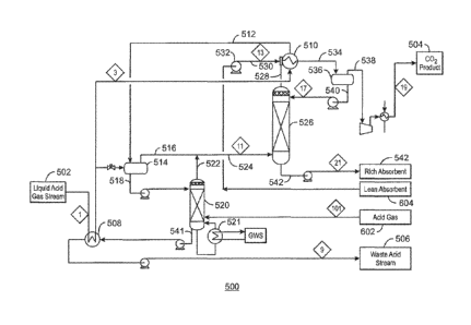
100591 Fig. 5 is a simplified process flow diagram of a CO2 separation
process 500 that
separates a liquid acid gas stream 502 into a CO2 product stream 504 and a
liquid acid waste
stream 506. The liquid acid gas stream 502 is partially vaporized in two heat
exchangers 508
and 510, while providing medium-temperature refrigeration duty to these
exchangers. The
use of the liquid acid gas stream 502 in these exchangers can reduce, or, in
some cases, even
eliminate, the need for an external refrigeration system to cool these
exchangers.
[00601 The partially vaporized acid gas 512 is flowed into a separation
vessel 514 to form
a vapor stream 516 and a liquid stream 518. The liquid stream 518 is pumped
into a bulk
liquid stripper 520. The bulk liquid stripper 520 is heated by a reboiler 521,
for example,
using a heating medium such as a glycol-water mixture.
10061] The vapor stream 516 and the overhead vapor 522 from the bulk
liquid stripper
520 are combined to form a vaporized CO2 stream 524 that is fed to the bottom
of an
absorbent column 526. The absorbent column 526 may use any number of physical
solvents,
such as Selexol, Purisol, Rectisol, and others. In this example. Selexol was
used for the
purposes of the process simulation calculations.
100621 In the absorbent column 526, the remaining 1-125 in the vaporized
CO-) stream 524
is removed by a counter current of physical solvent falling from the top of
the absorbent
column. The column overhead 528 is mixed with a lean Selexol stream 530 from
pump 532
- 16 -
CA 02857122 2014-05-27
and enters an absorber-exchanger 510. The absorber-exchanger 510 pre-saturates
the Selexol
with CO2 and removes the heat of absorption by exchanging heat with the feed
liquid acid gas
stream 502. This pre-saturation step allows the absorbent column 526 to
operate at a fairly
constant, low temperature and absorb the H2S in the vapor feed stream at a low
total Selexol
circulation rate, for example, in comparison to current solvent separation
processes that
operate at higher temperatures. The CO2 saturated Selexol stream 534 is flowed
into a flash
drum 536. The overhead vapor stream from the flash drum 536 provides a
purified CO2
stream 538. The liquid stream from the flash drum 536 is a pre-saturated,
chilled Selexol
stream 540, which is pumped to the absorbent column 526 to provide the
selective separation
of the purified CO2 and H2S
100631 The purified CO2 stream 538 can be compressed and cooled to the
desired
conditions for the CO2 product 504. The liquid stream 541 from the bottom of
the bulk liquid
stripper 520 can be pumped and sub-cooled by exchanging heat with the liquid
acid gas
stream 502 in exchanger 508, and further pumped to the desired injection or
transmission
conditions for the liquid acid waste stream 506. The rich Selexol stream 542
from the
bottoms of the absorbent column 526 is pumped to an absorbent regeneration
system 600,
discussed with respect to Fig. 6, for the extraction of the residual H2S.
100641 Fig. 6 is a simplified process diagram of an absorbent
regeneration system 600 that
removes acid gases 602 from a physical solvent steam from Fig. 5 and returns a
lean
absorbent stream 604 to the absorbent column 526 shown in Fig. 5. Like
numbered items are
as described with respect to Fig. 5. Since a pre-saturated, chilled Selexol
stream 540 is
injected into the absorbent column 526, the rich Selexol stream 542 is cool.
The rich Selexol
stream 542 is preheated in exchangers 606 and 608 to recover some
refrigeration duty, and
then further heated in an exchanger 610 with a heating medium, for example, a
glycol-water
.. stream.
100651 The pressure of the rich Selexol stream 542 is then progressively
reduced in stages
612, 614, 616, and 618 to allow some of the acid gas to be released in each
stage at
incrementally decreasing pressures. Although four stages are shown, the number
of stages
could be increased or decreased depending on the concentration of H2S in the
rich Selexol
- 17 -
CA 02857122 2014-05-27
stream 542. In a first stage 612 the rich Selexol stream 542 is fed to flash
drum 620. The
overhead vapor stream 622 can be cooled in an exchanger 606, allowing water to
condense
out and be recovered in a separation vessel 624, The recovered water stream
626 can be
further processed to remove more of the dissolved H2S, while the acid gas 602
is returned to
the bulk liquid stripper 520.
100661 The liquid stream 628 from the bottom of the flash drum 620 can be
flashed across
a valve 630 to lower the pressure prior to injection into a second flash drum
632 in the second
stage 614. The vapor stream 634 from the second flash drum 632 is fed to a
recompressor
636 and the pressured stream 638 is combined with the overhead vapor stream
622 from the
flash drum 622.
[0067] Similarly, the vapor stream 640 from a third stage 616 is fed to a
recompressor 642
and prior to being flowed through a heat exchanger 644, which can be cooled by
a glycol-
water stream from a glycol-water heating and cooling system (GWS) 646, as
discussed herein.
The cooled compressed stream 648 is passed through a separation vessel 650 to
remove
condensed water, and the remaining vapor stream is combined with the vapor
stream 634
from the second flash drum 632 to be fed into the recompressor 636,
[0068] The fourth stage 618 is operated in a similar fashion, with a
vapor stream 652 fed
to a recompressor 654 prior to being cooled in a heat exchanger 656. After
cooling, the vapor
stream 652 is flowed through a separation vessel 658 to remove condensed
water, prior to
being combined with the vapor stream 640 from the prior stage 616. These
pressures of the
vapor stream from each stage 612, 614, 616, and 618 can be matched to the
recompression
inter-stage pressures to minimize recompression power requirements.
100691 After the pressure reduction in the stages 612, 614, 616, and 618,
the reduced
pressure Selexol stream 660 is further heated in a rich/lean exchanger 662 and
charged to a
reboiled regeneration column 664. The reboiled regeneration column 664 is heat
by a steam
reboiler 666. The overhead vapor stream 668 is cooled in an ambient heat
exchanger 669 and
then processed in a similar manner to the vapor streams from the stages 612,
614, 616, and
618 to remove the remaining H2S. The bottom stream 670 from the reboiled
regeneration
- 18-
CA 02857122 2014-05-27
column 664 provides the lean Selexol stream 604, which is pumped through the
rich/lean
exchanger 662 and exchanger 608, before flowing to the absorber-exchanger 510
(Fig. 5).
[00701 The five wet vapor streams 622, 634, 640, 652, and 672 produced
during the
Selexol regeneration are routed to the recornpressors 636, 642, 654, and 674.
The wet vapor
streams 622, 634, 640, 652, and 672 enter at the appropriate inter-stage
pressures to minimize
the required compression power. After recompression, the regeneration gas at
each stage is
cooled to remove water. After all the regeneration gas is compressed and
mixed, it is cooled a
final time in exchanger 606 to condense as much remaining water as feasible.
The acid gas
stream 602 carries a small amount of water into the bulk liquid stripper 520.
The recovered
water stream 626, separated from all the compression inter-stages, is
reintroduced to the
regenerator reflux accumulator 676, to maintain the Selexol system's water
balance.
100711 The cooled, H2S-rich acid gas 602 is then injected into the bottom
of the bulk
liquid stripper 520. Here, the I-12S is reabsorbed by the liquid acid gas
releasing CO2 in its
place and reducing the amount of reboiler duty required to vaporize the
desired volume of
CO2. All the H2S is, thus, contained in the liquid acid waste stream 506
leaving the bottom of
the bulk liquid stripper 520.
[0072] Over half of the thermal energy used in the processes described
herein is at a low
enough low temperature, e.g., below about 150 F, so that the heat can be
supplied from the
compressor discharge coolers. Thus, a glycol water heating and cooling system
(GWS 646)
can be used to maximize the thermal efficiency of the overall system by
transferring heat from
locations it is generated (e.g., at the compressor discharge coolers) to
locations that it is used.
For example, the OWS 646 system can be heated at the exchangers 644, 656, and
678 in the
compressor inter-stages and cooled in the Selexol exchanger 610 and the bulk
stripper heaters,
minimizing additional utility and fuel requirements.
[0073] Fig. 7 is a block diagram of a method 700 for generating a CO2
product stream and
a liquid acid gas waste stream using a combined system. The method 700 begins
at block 702
with the separation of a liquid acid gas stream from a natural gas product.
The liquid acid gas
stream may be isolated using a cryogenic separation process as described with
respect to Fig.
4. However, any separation process that generates a liquid acid gas stream may
be used. At
- 19-
CA 02857122 2014-05-27
block 704, the liquid acid gas stream may be flowed into a bulk liquid
stripper to fractionate,
CO2 from the CO21112S mixture, as described with respect to Fig. 5. At block
706, the CO2
enriched vapor from the bulk liquid stripper is flowed to an absorber column.
At block 708
the vapor is treated with a physical solvent in the absorber column to remove
excess H2S from
the CO2. At block 710, the vapor from the overhead of the absorber column is
contacted with
a lean physical solvent stream to preload the physical solvent with the CO2.
The treated
stream is then used at block 708 to treat the vapor. At block 712, excess CO2
is flashed from
the physical solvent after preloading and, at block 714, the excess CO2 is
provided as a
product.
[00741 At block 716, the concentrated liquid acid gas stream isolated at
block 706 as the
bottoms of the bulk liquid stripper can be disposed of, for example, by
injection into a
disposal well. The rich physical solvent, e.g., containing a high
concentration of 112S and
CO2, can be processed at block 718 to remove the acid gases, as described with
respect to Fig.
6. At block 720, the acid gases can be returned to the bulk liquid stripper
for further
separation and to provide heating duty. The lean physical solvent generated at
block 718 can
be pretreated at block 710 to form the preloaded solvent.
100751 While the present techniques may be susceptible to various
modifications and
alternative forms, the exemplary embodiments discussed above have been shown
only by way
of example. However, it should again be understood that the techniques is not
intended to be
limited to the particular embodiments disclosed herein. Indeed, the present
techniques
include all alternatives, modifications, and equivalents falling within the
scope of the
appended claims. The scope of the claims should not be limited by particular
embodiments
set forth herein, but should be construed in a manner consistent with the
specification as a
whole.
- 20 -