Note: Descriptions are shown in the official language in which they were submitted.
81779940
1
CABLE COMPONENT WITH NON-FLAMMABLE MATERIAL
[00011
Field of the Invention
[0002] The present invention relates to components for cables, such as riser
and plenum
cables, that include non-flammable material, such as fiberglass, for flame and
burn resistance.
Background of the Invention
[0003] Conventional communication cables for both riser and plenum
applications
typically include a number of insulated conductors that are twisted together
in pairs 100 and
surrounded by an outer jacket 102, as seen in FIG. 1. Crosstalk or
interference often occurs
because of electromagnetic coupling between the twisted pairs within the cable
or other
components in the cable, thereby degrading the cable's electrical performance.
Also, as
networks become more complex and have a need for higher bandwidth cabling,
reduction of
cable-to-cable crosstalk (alien crosstalk) becomes increasingly important.
[0004] Bathers or separators, such as the separator 110 shown in FIG. 1, are
often used,
particularly in plenum applications, to separate and isolate the pairs of
conductors, thereby
reducing crosstalk interference. Such barriers and separators are normally
made of a flame
retardant insulation material or insulation materials that meet cable bum
tests, such as
fluoropolymers like FEP in the case of plenum cables tested per the
requirements of NI-PA
262 and flame retardant polyolefins in the case of riser cables which are
tested per UL 1666.
CA 2857179 2017-12-01
CA 02857179 2019-05-27
WO 2013/086013
PCT/US2012/067975
2
In other applications, such barriers also need to meet requirements for
standards such as tests
for Low-Smoke, Zero-Halogen or other burn tests similar to UL 1666 or NFPA
262.
[0005] However, such flame retardant insulative materials are typically
halogenated and
release toxic halogens when burned. Fluoropolymers in particular melt and drip
when
burned. Also, fluoropolymers are typically more expensive due to high demand.
[0006] Therefore, a need exists for cable components that meet industry
standard burn
requirements and that are less toxic and less expensive.
81779940
3
Summary of the Invention
[0006a1 According to an aspect of the present invention, there is
provided a cable
component, comprising: a main body, at least a part of the main body
comprising: an
insulation material; and one or more non-flammable portions formed of a non-
fluoropoly-mer
material, the one or more non-flammable portions disposed within the
insulation material; and
wherein the one or more non-flammable portions comprise about 25% or more, by
volume, of
the cable component, is flexible, and reduces the quantity of insulation
material of the main
body.
10006b1 According to another aspect of the present invention, there is
provided a cable,
comprising: a plurality of twisted pairs of insulated conductors; a separator
configured to
separate the plurality of twisted pairs of insulated conductors, the separator
comprising, a
main body having channels for retaining the plurality of twisted pairs of
insulated conductors,
the main body comprising a flame retardant insulation material, and one or
more non-
flammable portions formed from a non-fluoropolymer material, the one or more
non-
flammable portions disposed within the insulation material, and wherein the
one or more non-
flammable portions comprise about 25% or more, by volume, of the separator and
reduce the
quantity of the insulation material; and an outer jacket surrounding the
plurality of twisted
pairs of insulated conductors and the separator.
10006e1 According to another aspect of the present invention, there is
provided a cable,
comprising: a plurality of twisted pairs of insulated conductors; a separator
configured to
separate the plurality of twisted pairs of insulated conductors, the separator
comprising, a
main body, the main body comprising channels for retaining the plurality of
twisted pairs of
insulated conductors and being comprised of a highly flame retardant
insulation material, a
plurality of flexible, non-fluoropolymer fiberglass portions disposed within
the main body, the
plurality of flexible, non-fluoropolymer fiberglass portions reducing the
amount of the highly
flame retardant insulation material; and an outer jacket surrounding the
plurality of twisted
pairs of insulated conductors and the separator, and wherein the flexible, non-
fluoropolymer
fiberglass portions form about 25% or more, by volume, of the separator.
CA 2857179 2017-12-01
81779940
3a
[00071 Another aspect provides a cable component that comprises a main
body where
at least a part of the main body is formed of an insulation material, and at
least one non-
flammable portion is disposed in the insulation material of the main body. The
non-flammable
portion forms at least about 25% by volume of the cable component, is
flexible, and reduces
the amount of the insulation material of the main body, thereby reducing the
fuel load in the
cable component.
[0008] Another aspect relates to a cable that comprises a plurality of
twisted pairs of
insulated conductors and a separator that is configured to separate the
plurality of twisted
pairs of insulated conductors. The separator includes a main body that has
channels which
each retain one of the plurality of twisted pairs of insulated conductors,
respectively. The
main body is formed of an insulation material that is flame retardant. At
least one non-
flammable portion is disposed in the insulation material of the main body. The
at least one
non-flammable portion reduces the amount of the insulation material of the
main body,
thereby reducing the fuel load of the separator. An outer jacket surrounds the
plurality of
twisted pairs of insulated conductors and the separator.
[0009] Another aspect provides a cable that comprises a plurality of
twisted pairs of
insulated conductors and a separator that is configured to separate the
plurality of twisted
pairs of insulated conductors. The separator includes a main body that has
channels, each of
which retains one of the plurality of twisted pairs of insulated conductors.
The main body is
formed of a highly flame retardant insulation material. A plurality of
flexible
CA 2857179 2017-12-01
81779940
4
fiberglass portions are disposed in the insulation material of the main body.
The plurality of
flexible fiberglass portions reduce the amount of the insulation material of
the main body,
thereby reducing the fuel load of the separator. An outer jacket surrounds the
plurality of
twisted pairs of insulated conductors and the separator, such that the
flexible fiberglass
portions form at least about 25% by volume of said separator.
[0010] Other objects, advantages and salient features of some embodiments of
the
invention will become apparent from the following detailed description, which,
taken in
conjunction with the annexed drawings, discloses a preferred embodiment of the
present
invention.
CA 2857179 2017-12-01
81779940
Brief Description of the Drawines
[0011] A more complete appreciation of embodiments of the invention and many
of
the attendant advantages thereof will be readily obtained as the same becomes
better
understood by reference to the following detailed description when considered
in
connection with the accompanying drawings.
[0012] FIG. 1 is a cross-sectional view of a prior art cable and separator;
[0013] FIG. 2 is a cross-sectional view of a cable component according to a
first
exemplary embodiment of the present invention;
[0014] FIG. 3 is a cross-sectional view of a cable component according to a
second
exemplary embodiment of the present invention;
[0015] FIG. 4A is a cross-sectional view of a cable component according to a
third
exemplary embodiment of the present invention;
[0016] FIG. 4B is a partial perspective view of the cable component
illustrated in FIG.
4A;
[0017] FIG. 5 is a cross-sectional view of a cable component according to a
fourth
exemplary embodiment of the present invention;
[0018] FIG. 6 is a cross-sectional view of a cable component according to a
fifth
exemplary embodiment of the present invention: and
[0019] FIG. 7 is a cross-sectional view of a cable component according to a
sixth
exemplary embodiment of the present invention.
CA 2857179 2017-12-01
= 81779940
6
Detailed Description of Embodiments
[0020] Referring to FIGS. 2, 3, 4A, 4B, and 5-7, a cable component, such as a
separator,
according to exemplary embodiments of the present invention, incorporates a
non-
flammable material, such as fiberglass, therein to provide improved burn
properties and heat
resistance to the cable component. The non-flammable material may be
individual glass
fibers bunched together, fiberglass yarns, fiberglass rovings, chopped
fiberglass, woven
fiberglass tapes or sheets, and the like. These materials are desirable
because they have
optimal bum properties while also allowing the cable component to maintain
flexibility.
Other suitable non-flammable materials can also be employed, such as basalt
fibers, yams,
woven tapes, high temperature ceramic oxide fibers, other ceramic mica tapes,
and the like.
These materials are desirable because of their high temperature performance in
cable
applications. The non-flammable material replaces and thus reduces the amount
of the fuel
burning materials, such as FEP or polyolefin, of the separator, thereby
improving the burn
performance of the separator. The separators of the exemplary embodiments are
preferably
at least about 25% by volume non-flammable material.
[0021] In the case of plenum applications in particular, halogenated
fluoropolymers of
the cable component are displaced by the non-flammable material without
sacrificing burn
performance. That significantly reduces the content of costly and potentially
hazardous
halogenated materials in the cable. Also, many fluoropolymers when under
extreme heat
tend to melt and drip onto surfaces where they continue to smoke rather than
burn cleanly.
The non-flammable material, e.g. fiberglass, which replaces at least a portion
of the
CA 2857179 2017-12-01
CA 02857179 2019-05-27
WO 2013/086013
PCT/US2012/067975
7
fluoropolymers, limits the amount of molten material that can drip from the
cable and
smoke when heated. Also, in the present invention, it is possible to construct
a flame
retardant polyolefin separator in plenum applications by incorporating the non-
flammable
material therein to provide improved bum properties and heat resistance.
Typically flame
retardant polyolefins cannot be used for plenum applications to meet standard
requirements
because they typically tend to allow more flame spread than fluoropolymers.
However,
because the non-flammable material significantly reduces the amount of flame
retardant
polyolefin that would be needed in the cable component, it is now possible to
use the lower
cost non-fluoropolymer materials, such as polyolefin, and still maintain the
smoke and
flame spread performance required to meet the NFPA 262 tests. Furthermore, it
is also
possible with the present invention to construct a low-smoke, zero-halogen
plenum grade
pair separator and still meet the requirements of the NFPA 262 test.
[0022] In the case of riser applications where the requirements mandate
limited vertical
flame spread, burn performance of the cable component can be significantly
improved by
the addition of the non-flammable material according to the present invention.
And because
of the excellent burn properties of fiberglass, for example, the amount of
flame retardants
needed to meet requirements for riser applications is significantly reduced.
In general, the
excellent burn properties of the fiberglass also exceed those of the flame-
retardant
polyolefins, thereby improving overall performance in the riser burn test.
Also, because of
the reduction in fuel load resulting from displacing polymer material in the
separator with
the non-flammable material, like fiberglass, flame retardants elsewhere in the
cable can be
reduced. That allows for a reduction in the amount of flame retardants used in
the outer
CA 02857179 2019-05-27
WO 2013/086013
PCT/US2012/067975
8
jacket and insulation materials as well as other cable components, such as
barrier tapes in
shielded cables.
[0023] FIG. 2 illustrates a cable component or separator 210 according to a
first
exemplary embodiment of the invention. The separator 210 acts to isolate the
pairs 100 in the
cable. As an example, one or more pairs 100 may be located in the cable
adjacent on one
side 214 of the separator 210 and one or more pairs 110 may be located
adjacent the other
side 216 of the separator 210. The separator 210 has a main body 212 that is
substantially
flat. For example, the separator's main body 212 may be a tape. The main body
212 is
preferably made of an insulation material, such as a flame retardant polymer.
like FEP or a
highly flame retardant halogen-free polyolefin. Incorporated in the main body
212 is the
non-flammable material or portion 220 that preferably extends for the length
of the separator.
The non-flammable portion 220 is preferably flexible. For example, the non-
flammable
material 220 may be formed of a plurality of strands, such as fiberglass, that
displace a
portion of the insulation material of the main body 212 while maintaining the
flexibility of
the separator 210. As seen in FIG. 2, the non-flammable portion 220 is about
80% of the
separator 210.
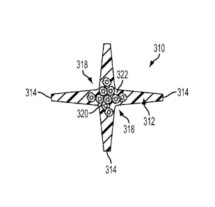
[0024] As seen in FIG. 3, a cable component or separator 310 according to a
second
exemplary embodiment of the present invention may be used to separate the
pairs 100 of the
cable similar to the separator 110 of FIG. 1. The separator 310 has a main
body 312 with a
generally cross-web shape in cross-section that includes a plurality of arms
314. The arms
314 extend from a center 322 of the separator 310 and may taper. Channels 318
are defined
between the arms 314 for receiving the pairs 100. Like the separator of the
first embodiment,
81779940
9
the main body 312 is preferably made of an insulation material. Provided in
the center 322 of
the separator 310 is the non-flammable portion 320 that preferably extends for
the length of
the separator. The non-flammable portion 320 may be, for example, a plurality
of bundles of
strands, such as fiberglass strands. The non-flammable portion 320 also
preferably forms
about 50% by volume of the separator 310.
[0025] As seen in FIGS. 4A and 4B, a cable component or separator 410
according to a
third embodiment of the present invention has a main body 412 with a generally
cross-web
shape in cross-section that includes a plurality of arms 414. The main body
412 is preferably
made of a flame retardant insulation material similar to the first and second
embodiments.
[0026] Each arm 414 of the separator 410 preferably has an enlarged end
section 416.
The enlarged end sections 416 may have any cross-sectional shape, such as
triangular, as seen
in FIG. 4A. Channels 418 arc defined between the enlarged end sections 416 and
the arms
414 that are configured to individually receive the pairs 100. Disposed in
each end section
416 may be a non-flammable portion 420. The non-flammable portions 420 extend
through
the length of the separator 410, as seen in FIG. 4B. Each non-flammable
portion 420 may
have any cross-sectional shape, such as substantially circular (FIG. 4A) or
substantially
square (FIG. 4B). Although it is preferable that each end section 416 of the
arms 414
includes the non-flammable portion 420, any number of the end sections 416 may
have the
non-flammable portion 420 including just one end section 416.
[0027] As seen in FIG. 5, a cable component 510 according to a fourth
exemplary
embodiment of the present invention is a separator that includes a main body
512 that has a
substantially cross-web shape in cross-section. The main body 512 is
preferably made of a
CA 2857179 2017-12-01
CA 02857179 2019-05-27
WO 2013/086013
PCT/US2012/067975
flame retardant polymer like previous embodiments and includes a plurality of
arms 514.
The arms 514 extend from a center 522 of the separator and may taper. Channels
518 are
defined between the arms 514 for receiving the pairs 100.
[0028] Each arm 514 of the separator 510 may have a non-flammable portion 520
extending for the length of the separator, similar to the non-flammable
portions 220 of the
first embodiment. Each non-flammable portion 520 preferably has a generally
flat shape that
is substantially linear in cross-section, as seen in FIG. 5. Each non-
flammable portion 520
preferably extends approximately the width of each arm 514, leaving the center
522 of the
separator free of the non-flammable material. However, any portion of the aims
514 may
include the non-flammable portion 520. Alternatively, the non-flammable
portion 520 may
also be added to the center 522 of the separator. For example, one non-
flammable portion
520 may span across two arms 514 and through the center 522. Although it is
preferable that
each arm 514 include its own non-flammable portion 520, any number of the aims
514 may
include the non-flammable portion 520, including just one arm 514.
[0029] As seen in FIG. 6, a cable component or separator 610 according to a
fifth
exemplary embodiment of the present invention is similar to the separator 510
of the fourth
embodiment, except that the non-flammable portions 620 span more than one arm
614 of the
separator 610. Like the separator 510 of the fourth embodiment, the separator
610 of the fifth
embodiment has a main body 612 with a cross-web shape that includes a
plurality of arms
614. Non-flammable portions 620 are each disposed in two of the arms 614 and
the center
622 of the separator, such that each portion 620 has a substantially L-shape
in cross-section,
as seen in FIG. 6. Each non-flammable portion 620 preferably extends for the
length of the
CA 02857179 2019-05-27
WO 2013/086013
PCT/US2012/067975
11
separator 610. Although it is preferable to use at least two non-flammable
portions 620, as
illustrated in FIG. 6, only one non-flammable portion 620 may be used.
[0030] As seen in FIG. 7, a cable component or separator 710 according to a
sixth
exemplary embodiment of the present invention combines aspects of the previous
embodiments. In particular, the separator 710 has a generally cross-web shape
similar to the
second, fourth and fifth embodiments. The separator 710 has a main body 712
that
incorporates non-flammable portions 720 and 722. The non-flammable portion
720, for
example, may be generally flat with a substantially linear cross-section that
spans two arms
714 of the main body 712. On either side of the flat non-flammable portion 720
may be non-
flammable portions 722 that preferably form bundles of fibers or strands woven
into a flat
fabric and folded into L-shape then disposed in the other two arms of the
separator 710. As
with the other embodiments, the non-flammable portions 720 and 722 are
preferably flexible
and not rigid.
[0031] While particular embodiments have been chosen to illustrate the
invention, it will
be understood by those skilled in the art that various changes and
modifications can be made
therein without departing from the scope of the invention as defined in the
appended claims.
For example, any separator may incorporate the non-flammable material or
portion as taught
by the present invention and are not limited to the embodiments described
above.
Additionally, any combination of the above non-flammable portions may be
incorporated into
the separator. Also, other cable components, such as barriers, wraps and
fillers, may
incorporate fiberglass, as taught by the present invention.