Note: Descriptions are shown in the official language in which they were submitted.
CA 02857471 2014-05-29
MICRO-COIL ASSEMBLY
CROSS-REFERENCE TO RELATED APPLICATIONS
This application claims the benefit of Korean Patent Application No. 10-2011-
0128649, filed
on 12 02, 2011, in the Korean Intellectual Property Office, the disclosure of
which is
incorporated herein in its entirety by reference.
BACKGROUND
[0001]
The inventive concept relates to a micro-coil assembly, and more particularly,
to a
micro-coil assembly which enables a micro-coil unit to be conveniently and
accurately
separated from the micro-coil assembly so that the micro-coil unit can be
precisely inserted in
an aneurysm or other vascular malformation of a patient, thereby efficiently
meeting a
surgical purpose of an operator.
[0002] A cerebral aneurysm (i.e., acute subarachnoid hemorrhage) refers to
cerebrovascular swelling on the wall of an artery because of congenitally weak
cerebral
artery or because of arteriosclerosis, bacterial infections, a head wound,
brain syphilis, etc.
Such a cerebral aneurysm is suddenly developed without an initial symptom, and
brings
extreme pain during an attack of the cerebral aneurysm. 15% of cases die
suddenly, 15%
die under medical treatment, and 30% survive after treatment but feel the
acute aftereffect.
Therefore, the cerebral aneurysm may be a very deadly disease.
[0003] A
cure for the cerebral aneurysm is divided into an invasive therapy and a
non-invasive therapy. Of these, the non-invasive therapy fills the cerebral
aneurysm with a
micro-coil to induce thrombus, thereby preventing an additional inflow of
blood and
decreasing risk of a ruptured aneurysm (embolization). The non-invasive
therapy has been
being widely researched and developed since it can ease the aftereffect due to
brain surgery,
have advantage of short hospitalization, and so on.
[0004]
The micro-coil assembly used in the non-invasive therapy roughly includes a
micro-coil unit and a coil-pusher unit for delivering the micro-coil unit to
an aneurysm of a
patient. When the micro-coil unit starts being inserted in the aneurysm, an
operator
separates the micro-coil unit from the coil-pusher unit. As a method of
separating the
micro-coil unit from the coil-pusher unit, there are mechanical methods,
chemical methods,
thermal methods, etc.
=
CA 02857471 2014-05-29
[0005]
Among them, the most convenient and accurate method is the mechanical method.
A conventional mechanical method for the separation is achieved by releasing a
locking state
between a hook provided in an end part of the micro-coil unit and a hook
provided in an end
part of the coil-pusher unit. However, such a releasing method is not only
complicated but
also difficult to separate the micro-coil unit from the coil-pusher accurately
at a desired
position and desired timing.
[0006]
Accordingly, research and development have to be carried out on a micro-coil
assembly in which the micro-coil unit can be conveniently and accurately
separated from the
coil-pusher unit.
SUMMARY
[0007]
The present inventive concept is to provide a micro-coil assembly which
enables a
micro-coil unit to be conveniently and accurately separated from the micro-
coil assembly so
that the micro-coil unit can be precisely inserted in an aneurysm or other
vascular
malformation of a patient, thereby efficiently meeting a surgical purpose of
an operator.
[0008]
According to an aspect of the present inventive concept, there is provided a
micro-coil assembly including a micro-coil unit which is inserted into an
aneurysm or other
vascular malformation of a patient and prevents inflow of blood by inducing
thrombus, a coil
pusher unit which is arranged adjacent to the micro-coil unit and controllably
delivers the
micro-coil unit to the aneurysm or other vascular malformation of the patient,
a tensile wire
which is relatively movably arranged in the coil pusher unit, a tie which
connects the
micro-coil unit and the tensile wire, and a tie cutting unit which is arranged
adjacent to the
coil pusher unit such that at least a part of the tie cutting unit is movable
between a setting
position for maintaining the tie in a tied state and a cutting position for
cutting the tie, and
cuts the tie when moved to the cutting position.
[0009]
The tie cutting unit may include a first blade which is coupled to the tensile
wire
and moves linked with a movement of the tensile wire.
[0010]
The tie cutting unit may further include a second blade which is arranged
adjacent
to the coil pusher unit and cuts the tie by the interaction with the first
blade when the first
blade is moved to the cutting position.
[0011]
The second blade may be fixedly arranged not to move into the coil pusher
unit, a
second blade passing hole through which the tie passes in a lengthwise
direction of the coil
2
CA 02857471 2014-05-29
pusher unit may be formed in the second blade, and the first blade may be
inserted in the
second blade passing hole when cutting the tie.
[0012] An inner diameter of the second blade passing hole may be
greater than an outer
diameter of the first blade and less than a sum of the outer diameter of the
first blade and a
thickness of the tie.
[0013] A first blade passing hole through which the tie passes in the
lengthwise direction
of the coil pusher unit may be formed in the first blade.
[0014] The tie may include a first knot part which is knotted at a
rear end portion of the
tensile wire, a first extension part which is connected to the first knot part
and passes through
the second blade passing hole and the outside of the first blade, a second
extension part which
is connected to the first extension part and passes through the first blade
passing hole, and a
second knot part which is connected to the second extension part and knotted
at the rear end
portion of the tensile wire adjacent to the first knot part.
[0015] The cutting position may be a position where the rear end
portion of the first blade
contacts a front end portion of the second blade to cut the first extension
part.
[0016] The second blade may be fixedly arranged at a front end portion
of the coil pusher
unit, a second blade passing hole through which the tie passes in a lengthwise
direction of the
coil pusher unit and a second blade crossing hole which is formed in a
direction crossing the
lengthwise direction of the coil pusher unit and communicates with the second
blade passing
hole which may be formed in the second blade, the first blade may be arranged
to be capable
of relatively moving with respect to the second blade, and a first blade
passing hole in the
lengthwise direction of the coil pusher unit and a first blade crossing hole
which is formed in
a direction crossing the lengthwise direction of the coil pusher unit and
communicates with
the second blade passing hole may be formed in the first blade.
[0017] The tie may include a first knot part which is knotted at a rear end
portion of the
tensile wire, a first extension part which is connected to the first knot part
and passes through
the first blade crossing hole and the second blade passing hole, a second
extension part which
is connected to the first extension part and passes through the first blade
passing hole and the
second blade passing hole, and a second knot part which is connected to the
second extension
part and knotted at the rear end portion of the tensile wire adjacent to the
first knot part.
[0018] The cutting position may be a position where the first extension
part is cut by the
interaction of the first blade and the second blade as the first blade moves
to block the second
blade crossing hole.
3
CA 02857471 2014-05-29
[0019] Any one of an inner wall forming the first blade crossing hole
and an inner wall
forming the second blade crossing hole may be inclined to have an inner
diameter increasing
toward an upper end.
[0020] The tensile wire may include a knot part stopper which
restricts movement of at
least any one of the first knot part and the second knot part.
[0021] The micro-coil unit may include a thrombus-leading coil which
is inserted in the
aneurysm or other vascular malformation of the patient and transformed into a
previously
determined shape to clot blood, and an expansion-resistive core which is
arranged passing
through an inside of the thrombus-leading coil, wherein the tie may connect
the tensile wire
and the expansion-resistive core.
[0022] The micro-coil unit may further include a core support member
which is coupled
to the expansion-resistive core and supports the expansion-resistive core in
the
thrombus-leading coil.
[0023] The coil pusher unit may include a pusher tube in which the
tensile wire is
accommodated.
[0024] A screw pattern may be provided in the pusher tube at a part
adjacent to the
micro-coil unit, the coil pusher unit may further include a coil stopper which
is coupled to a
leading end of the screw pattern of the pusher tube, forms an opening through
which the tie
passes, and prevents the micro-coil unit from moving into the pusher tube
during cutting of
the tie.
[0025] The tie may be a suture, and the tensile wire may be
accommodated in the coil
pusher unit and an end portion of the tensile wire may be exposed to the
outside of the coil
pusher unit for an operation of the tensile wire.
BRIEF DESCRIPTION OF THE DRAWINGS
[0026] Exemplary embodiments of the inventive concept will be more
clearly understood
from the following detailed description taken in conjunction with the
accompanying drawings
in which:
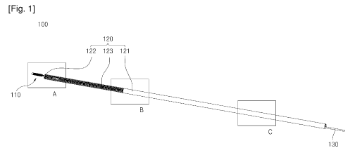
[0027] FIG. 1 is a perspective view of a micro-coil assembly according to
an exemplary
embodiment of the present inventive concept;
[0028] FIG. 2 is an enlarged perspective view of a part A in FIG. 1;
[0029] FIG. 3 is an
enlarged perspective view of a part B in FIG. 1;
[0030] FIG. 4 is an
enlarged perspective view of a part C in FIG. 1;
4
CA 02857471 2014-05-29
[0031]
FIG. 5 is a cross-sectional view schematically illustrating the structure of a
tie
cutting unit in the micro-coil assembly of FIG. 1;
[0032]
FIG. 6 is a view illustrating a process of cutting a tie in the micro-coil
assembly of
FIG. 1;
[0033] FIG. 7 is
a schematic view illustrating that the micro-coil assembly of FIG. 1 is
inserted in an arteriovenous malformations aneury of a patient;
[0034]
FIG. 8 is a perspective view illustrating a micro-coil assembly according to
another exemplary embodiment of the present inventive concept;
[0035]
FIG. 9 is an enlarged perspective view illustrating the inside of an area E in
FIG.
8;
[0036]
FIG. 10 is a cross-sectional view schematically illustrating the structure of
a tie
cutting unit in the micro-coil assembly of FIG. 8;
[0037]
FIG. 11 is a view illustrating a process of cutting a tie in the micro-coil
assembly
of FIG. 8; and
[0038] FIG. 12 is
a cross-sectional view schematically illustrating the structure of a tie
cutting unit in a micro-coil assembly according to another exemplary
embodiment of the
present inventive concept.
DETAILED DESCRIPTION OF THE EMBODIMENTS
[0039]
The attached drawings for illustrating embodiments of the inventive concept
are
referred to in order to gain a sufficient understanding of the inventive
concept and the merits
thereof.
[0040]
Hereinafter, the inventive concept will be described in detail by explaining
embodiments of the inventive concept with reference to the attached drawings.
[0041]
FIG. 1 is a perspective view of a micro-coil assembly according to an
exemplary
embodiment of the present inventive concept. FIG. 2 is an enlarged perspective
view of a
part A in FIG. 1. FIG. 3 is an enlarged perspective view of a part B in FIG.
1. FIG. 4 is an
enlarged perspective view of a part C in FIG. 1. FIG. 5 is a cross-sectional
view
schematically illustrating the structure of a tie cutting unit in the micro-
coil assembly of FIG.
1.
FIG. 6 is a view illustrating a process of cutting a tie in the micro-coil
assembly of FIG. 1.
FIG. 7 is a schematic view illustrating that the micro-coil assembly of FIG. 1
is inserted in an
arteriovenous malformations aneury of a patient.
5
CA 02857471 2014-05-29
[0042] As shown therein, a micro-coil assembly 100 in this embodiment
includes a
micro-coil unit 110 to be inserted in an aneurysm M or other vascular
malformation of a
patient to induce thrombus, thereby preventing inflow of blood, a coil pusher
unit 120
arranged adjacent to the micro-coil unit 110 and carrying the micro-coil unit
110 to the
aneurysm M or other vascular malformation of the patient, a tensile wire 130
arranged in
the coil pusher unit 120 to be relatively moveable therein, a tie 140
connecting the micro-coil
unit 110 and the tensile wire 130, and a tie cutting unit 150 arranged
adjacent to the coil
pusher unit 120 such that at least a part thereof can move between a setting
position for
maintaining the tie 140 in a tied state and a cutting position for cutting the
tie 140, and cutting
the tie 140 when moved to the cutting position.
[0043] The micro-coil unit 110 is inserted into the aneurysm M or
other vascular
malformation of the patient and induces thrombus, thereby preventing inflow of
blood.
The micro-coil unit 110 includes a thrombus-leading coil 111 that is changed
to a previously
determined shape to induce thrombus when inserted in the aneurysm M of the
patient, and an
expansion-resistive core 112 penetrating the inside of the thrombus-leading
coil 111.
[0044] The thrombus-leading coil 111 is manufactured by winding a
platinum wire
having a proper diameter around a coil-winding device (mandrel) and then
applying heat
treatment to it in a high-temperature oven. Here, the coil-winding device is
provided to
have a shape corresponding to the shape of the thrombus-leading coil 111 to be
transformed
in the aneurysm M of a patient. Also, the proper diameter is determined on the
basis of the
size of a patient's aneurysm M. Alternatively, the diameter of the thrombus-
leading coil
111 may be changed on the basis of the shape of the thrombus-leading coil 111
before the
transformation, the flexibility of the thrombus-leading coil 111, the shape of
the
thrombus-leading coil 111 transformed within the aneurysm M, etc.
[0045] The expansion-resistive core 112 is changed to have a previously
determined
shape within the aneurysm M of the patient, so that the thrombus-leading coil
111 can be
accurately positioned within the aneurysm M. If the thrombus-leading coil 111
is directly
pushed or pulled instead of the expansion-resistive core 112, there may be a
gap or close
contact between the Nth winding part and the (N+1)th winding part of the
thrombus-leading
coil 111 since thrombus-leading coil 111 is wound spirally.
[0046] Accordingly, the expansion-resistive core 112 is provided to
solve this problem.
An operator (e.g., surgeon or the like) who operates on a patient for the
cerebral aneurysm
precisely pushes and pulls the expansion-resistive core 112, within the micro-
catheter X, so
that the thrombus-leading coil 111 connected to the expansion-resistive core
112 can be
6
CA 02857471 2014-05-29
minutely adjusted. That is, the expansion-resistive core 112 is not easily
transformed even
when pushed or pulled, so that an operator can accurately insert the thrombus-
leading coil
111 in the aneurysm M.
[0047]
The expansion-resistive core 112 is made of a polymer, which is produced by
polymerizing molecules, as being the opposite of a monomer. The expansion-
resistive core
112 includes one selected among various kinds of polymers such as
polypropylene, nylon,
polyamide monofilament, and polyamide composite filament. Polypropylene is a
thermoplastic resin produced by polymerizing propylene; nylon is the generic
term for a
synthesized high molecule polyamaide, which refers to a high molecule shaped
like a chain
connected with -CONH-; the polyamide monofilament is a monofilament provided
with
polyamide as a polymer having a structure of an aliphatic or aromatic amide
backbone; and
the polyamide composite filament is a composite filament provided with
polyamide.
[0048]
The expansion-resistive core 112 made of the polymer is not only flexible but
also
resistive to the expansion, so that it can be advantageously used as a framing
coil, a filling
coil, or a finishing coil. Here, the framing coil is a coil that is first
inserted in the aneurysm
M of the patient and provides a frame to be filled with the filling coil; the
filling coil is a coil
to be filled in the framing coil; and the finishing coil is a coil to be
filled in a minute gap of
the framing coil not filled with the filling coil.
[0049]
Alternatively, the expansion-resistive core 112 may be made of Nitinol. The
Nitinol is non-magnetic alloy formed by mixing nickel and titanium in
approximately the
same ratio.
[0050]
Meanwhile, one end part of the expansion-resistive core 112 adjacent to the
coil
pusher unit 120 is shaped like a loop, and the other end part thereof is
shaped like a ball or a
tip-ball (TB) formed by melting or welding part of the expansion-resistive
core 112,
depending on the type of material used for this component.
Specifically, the
expansion-resistive core in this embodiment is shaped like double loops each
of which has a
loop shape and which are spaced apart from each other in a vertical direction.
[0051]
Like this, the one end part of the expansion-resistive core 112 is shaped like
a loop,
so that the tie 140 can penetrate the inside of the expansion-resistive core
112 and easily tie
the expansion-resistive core 112. Thus, the expansion-resistive core 112 is
connected to the
tensile wire 130 via the tie 140.
[0052]
Further, the micro-coil unit 110 further includes a core support member 113
that is
connected to the expansion-resistive core 112 and supporting the expansion-
resistive core
112 in the thrombus-leading coil 111. The core support member 113 is provided
at the
7
CA 02857471 2014-05-29
opposite side of the tip-ball (TB). As the core support member 113 is provided
at the
opposite side of the tip-ball (TB) to support the expansion-resistive core
112, the
expansion-resistive core 112 is stably arranged in an internal cavity of the
thrombus-leading
coil 111.
[0053] Meanwhile,
the other end part of the expansion-resistive core 112 is formed with a
tip-ball (TB), so that a wall of an artery can be protected from being injured
by the
thrombus-leading coil 111 while the thrombus-leading coil 111 is inserted into
the aneurysm
M of the patient.
[0054]
The tip-ball (TB) is formed by melting the expansion-resistive core 112 at a
temperature equal to or above the melt temperature of the expansion-resistive
core 112
material.
This can be accomplished by applying heat capable of melting the
expansion-resistive core 112 material in the form of convective heated air,
conductive heat or
heat radiating from a source such as a soldering iron. Alternatively, if a
metallic material is
used for the expansion-resistive core 112, the tip-ball (TB) may be formed by
arc-welding the
other end part opposite to the one end part adjacent to the coil pusher unit
120 of the
expansion-resistive core 112. Particularly, the tip-ball (TB) in this
embodiment is formed
by electric arc welding the other end part of the expansion-resistive core
112, in which the
electric arc welding process melts the thrombus-leading coil 111 material into
a spherical
shape. Some metallic materials may require the arc-welding process to be
performed in an
inert-gas vacuum.
[0055]
The electric arc welding method is proper to form the tip-ball (TB) of the
expansion-resistive core 112 in this embodiment since no coating material is
used, no slag is
generated, and precise welding is possible. However, the right scope of the
present
inventive concept is not limited to this method of forming the tip-ball (TB).
Alternatively,
the tip-ball (TB) in this embodiment may be formed by applying not the
electric arc welding
but another welding method to the other end of the expansion-resistive core
112.
[0056]
The thrombus-leading coil 111 is fixed to the expansion-resistive core 112 as
one
end part thereof is in contact with the tip-ball (TB). Alternatively, the tip-
ball (TB) may be
provided by applying the arc-welding between one end part of the thrombus-
leading coil 111
and one end part of the expansion-resistive core 112. That is, the tip-ball
(TB) may be
provided by not applying the welding to the other end part of the expansion-
resistive core 112
but applying the arc-welding between one end part of the thrombus-leading coil
111 and the
other end part of the expansion-resistive core 112.
8
CA 02857471 2014-05-29
[0057] Yet another method of forming a tip-ball (TB) is to use an
adhesive that forms a
spherical shape upon application during the manufacturing process and secures
the
expansion-resistive core 112 to the end of the thrombus leading coil 111. The
adhesive
would be an implant-grade polymer, such as n-butyl cyanoacrylate or co-polymer
such as an
epoxy. Depending on the type of adhesive used, the tip-ball (TB) is formed
upon curing of
the adhesive with ultraviolet light or high-temperature application.
[0058] The coil pusher unit 120 is arranged adjacent to the micro-coil
unit 110 and carries
the micro-coil unit 110 to the aneurysm M of the patient. The coil pusher unit
120 includes
a pusher tube 121 in which the tensile wire 130 is accommodated.
[0059] The pusher tube 121 may be made of metal alloy such as Nitinol or
300-series
stainless steel; a rigid polymer such as polyetheretherketon (PEEK); or a
rigid polymer tube
formed by mechanically combining the rigid polymer and the metal alloy.
[0060] In this embodiment, the pusher tube 121 is provided with a
screw pattern 123,
which is comprised of a metallic coil laminated with a polymer jacket, making
this portion of
the pusher tube 121easy to bend and adjacent to the micro-coil unit 110. The
screw pattern
123 provided in the pusher tube 121 may prevent the pusher tube 121 from being
abruptly
folded at a particular position so that the pusher tube 121 may be smoothly
bent. Further, an
external protective polymer tube (not shown) may be coupled to an outer
surface of the
pusher tube 121 having the screw pattern 123.
[0061] The screw pattern 123 is intended to make the pusher tube 121 more
flexible for
smoother navigation into a patient's neurovasculature. An alternative method
of making the
pusher tube flexible is to create a pattern of multiple adjacent slots cut on
either side of the
distal section of the solid tube, 180 degrees apart, where each slot is cut to
a depth less than
half of the tube diameter. Adjacent slots may also alternate from 5 degrees
to 90 degrees,
such that no preferential bending exists in the pusher tube.
[0062] In this embodiment, the coil pusher unit 120 further includes a
coil stopper 122
that is coupled to a leading end of the screw pattern 123 of the pusher tube
121, forms an
opening through which the tie 140 passes, and prevents the micro-coil unit 110
from moving
into the pusher tube 121 during cutting of the tie 140.
[0063] The coil stopper 122 facilitates cutting of the tie 140 by
restricting the micro-coil
unit 110 from moving to the inside of the screw pattern 123 during the cutting
of the tie 140.
[0064] The tensile wire 130 is arranged to be relatively movable with
respect to the coil
pusher unit 120. In this embodiment, the tensile wire 130 is arranged in the
pusher tube 121
to be capable of relatively moving with respect to the pusher tube 121.
Further, for an
9
=
CA 02857471 2014-05-29
operation of the tensile wire 130, one end part of the tensile wire 130 is
exposed to the
outside of the pusher tube 121.
[0065]
As describe later, the tie 140 is connected to the tensile wire 130 via knots
141
and 144. A knot part stopper 131 for restricting the movements of the knots
141 and 144 is
provided on the tensile wire 130, which will be described later for
convenience of
explanation.
[0066]
The tie 140 connects the micro-coil unit 110 and the tensile wire 130. As the
opposite ends of the tie 140 form knots on the tensile wire 130, the tie 140
connects the
micro-coil unit 110 and the tensile wire 130. The arrangement of the tie 140
will be
described later for convenience of explanation. The tie 140 in the present
embodiment may
be a suture.
[0067]
The tie cutting unit 150 is arranged adjacent to the coil pusher unit 120 such
that
at least a part thereof can move between the setting position for maintaining
the tie 140 in a
tied state and the cutting position for cutting the tie 140, and cuts the tie
140 when moved to
the cutting position. In this embodiment, the tie cutting unit 150 is arranged
adjacent to the
coil pusher unit 120.
[0068]
The tie cutting unit 150 includes a first blade 151 coupled to the tensile
wire 130
and moving linked with the movement of the tensile wire 130. The first blade
151 is
coupled to an end portion of the tensile wire 130 at one side thereof to move
linked with the
movement of the tensile wire 130.
[0069]
As the first blade 151 is linked with the movement of the tensile wire 130,
the
movement of the tensile wire 130 moves the first blade 151 between the setting
position for
maintaining the tie 140 in a tied state and the cutting position for cutting
the tie 140, in the
coil pusher unit 120.
[0070] To
facilitate cutting of the tie 140 at the cutting position, the tie cutting
unit 150
further includes a second blade 155 provided at the coil pusher unit 120 to
cut the tie 140 by
the interaction of the first blade 151 when the first blade 151 is moved to
the cutting position.
[0071]
The first blade 151 and the second blade 155 may be made of 300-series
stainless
steel.
[0072] In this
embodiment, the second blade 155 is fixedly arranged so as not to be
moved into the pusher tube 121. Further, the first blade 151 relatively moves
in the screw
pattern 123 to approach and be separated from the second blade 155.
[0073]
In this embodiment, the second blade 155 is arranged adjacent to the pusher
tuber
121 and may be fixedly arranged in the pusher tube 121.
CA 02857471 2014-05-29
[0074] The first blade 151 arranged to be capable of relatively moving
with respect to the
second blade 155 is moved toward the second blade 155 due to the movement of
the tensile
wire 130 during the cutting of the tie 140 and cuts the tie 140 by the
interaction with the
second blade 155. A cutting part of the tie 140 will be described later for
convenience of
explanation.
[0075] A second blade passing hole 156 through which the tie 140
passes in a lengthwise
direction of the coil pusher unit 120 is formed in the second blade 155. A
first blade passing
hole 152 through which the tie 140 passes in a lengthwise direction of the
coil pusher unit
120 is formed in the first blade 151. Accordingly, during the cutting of the
tie 140, a part of
the first blade 151 is inserted into the second blade pass hole 156, thereby
facilitating the
cutting of the tie 140.
[0076] The tie 140 includes a first knot part 141 knotted at the rear
end portion of the
tensile wire 130, a first extension part 142 connected to the first knot part
141 and passing
through the second blade passing hole 156 and the outside of the first blade
151, a second
extension part 143 connected to the first extension part 142 and passing
through the first
blade passing hole 152, and a second knot part 144 connected to the second
extension part
143 and knotted at the rear end portion of the tensile wire 130 adjacent to
the first knot part
141.
[0077] The first extension part 142 passes through the second blade
passing hole 156 to
be cut by the relative movement of the first and second blades 151 and 155,
particularly by
passing through the outside of the first blade 151, not the inside of the
first blade 151.
[0078] Thus, during the cutting of the tie 140, the first and second
blades 151 and 155 cut
the first extension part 142. Here, the cutting position is a position where
the rear end
portion of the first blade 151 contacts the front end portion of the second
blade 155.
[0079] Further, in this embodiment, to facilitate the cutting of the first
extension part 142
due to the contact of the rear end portion of the first blade 151 contacts the
front end portion
of the second blade 155, an inner diameter D2 of the second blade passing hole
156 is greater
than an outer diameter D1 of the first blade 151 and less than a length D3
that is a sum of the
outer diameter D1 of the first blade 151 and a thickness T of the tie 140.
[0080] When the inner diameter D2 of the second blade passing hole 156 is
less than the
length D3 that is a sum of the outer diameter D1 of the first blade 151 and
the thickness T of
the tie 140, the rear end portion of the first blade 151 inserted into the
second blade passing
hole 156 may easily cut the first extension part 142 of the tie 140.
11
CA 02857471 2014-05-29
[0081] The tensile wire 130 includes the knot part stopper 131 that
restricts movement of
at least one of the first and second knot parts 141 and 144. In this
embodiment, the knot
part stopper 131 restricts the first and second knot parts 141 and 144 from
sliding along the
tensile wire 130 in a direction toward the first blade 151 in a process of
pulling the first blade
151 toward the second blade 155 to cut the tie 140.
[0082] As such, the micro-coil assembly 100 according to the present
embodiment may
conveniently and accurately cut the micro-coil unit 110 from the micro-coil
assembly 100 by
moving the tie cutting unit 150 from the setting position for maintaining the
tie 140 in a tied
state and to the cutting position for cutting the tie 140 and cutting the tie
140 connecting the
micro-coil unit 110 and the tensile wire 130.
[0083] The operation of the micro-coil assembly 100 according to the
present
embodiment will now be described in detail.
[0084] The micro-coil assembly 100 is inserted into the aneurysm M on
an artery along a
cavity X1 of the micro-catheter X extended from a proper insertion starting
position such as
the femoral region of the patient to the aneurysm M. That is, the micro-
catheter X extended
to arteriovenous malformations aneury M is first inserted, and then the micro-
coil assembly
100 is inserted along the micro-catheter X. The micro-coil assembly 100 is
manufactured to
have a very small diameter and thus have certain flexibility inside the micro-
catheter X, so
that it can be conveniently inserted.
[0085] The micro-coil unit 110 connected to the coil pusher unit 120 is not
randomly
deformed within the micro-catheter X according to the stress applied by an
inner wall of the
micro-catheter X, and is carried as it is to the aneurysm M.
[0086] If the micro-coil unit 110 is inserted into the aneurysm M of
the patient, the first
blade 151 is pulled toward the second blade 155 by pulling the tensile wire
130. Then, the
micro-coil unit 110 is restricted from being inserted into the coil pusher
unit 120 by the coil
stopper 122.
[0087] As the first blade 151 is gradually moved toward the second
blade 155, the first
blade 151 is moved to the cutting position for cutting the tie 140. As the
rear end portion of
the first blade 151 is engaged with the front end portion of the second blade
155 at the cutting
position, the first extension part 142 of the tie 140 is cut.
[0088] Next, the tie 140 that is cut is released from the expansion-
resistive core 112. As
a result, the micro-coil unit 110 is separated from the micro-coil assembly
100.
12
CA 02857471 2014-05-29
[0089]
Since the tie 140 is tied to the tensile wire 130 through the first and second
knot
parts 141 and 144, even if the tie 140 is cut, the tie 140 is not separated
from the tensile wire
130.
[0090]
As the tie 140 is cut, the micro-coil unit 110 is separated from the micro-
coil
assembly 100 and is completely inserted in the aneurysm M of the patient.
[0091]
The micro-coil unit 110, which comes out of the end of the micro-catheter X
and
is inserted in the aneurysm M, is released from the stress applied by the
inner wall of the
micro-catheter X, so that the micro-coil unit 10 can be transformed to have a
previously
determined shape while undergoing the heat treatment, thereby filling the
aneurysm M.
[0092] The micro-
coil unit 110 comes out of the end of the micro-catheter X and is
transformed to have a preset random shape such as a two-dimensional spiral
shape or a
three-dimensional spiral complex pattern. The transformed shape of the micro-
coil unit 110
is previously determined depending on the size, the shape and other various
data of the
aneurysm M of the patient.
[0093] In the
micro-coil assembly 100 according to this embodiment, as the tie 140
connecting the micro-coil unit 110 and the tensile wire 130 is configured to
be cut when the
tie cutting unit 140 moving between the setting position and the cutting
position moves to the
cutting position. Thus, the micro-coil unit 110 is conveniently and accurately
separated
from the micro-coil assembly 100 and precisely inserted in the aneurysm M of
the patient,
thereby efficiently meeting a surgical operation of an operator.
[0094]
FIG. 8 is a perspective view illustrating a micro-coil assembly 100a according
to
another exemplary embodiment of the present inventive concept. FIG. 9 is an
enlarged
perspective view illustrating the inside of an area E in FIG. 8. FIG. 10 is a
cross-sectional
view schematically illustrating the structure of a tie cutting unit in the
micro-coil assembly of
FIG. 8. FIG. 11 is a view illustrating a process of cutting a tie in the micro-
coil assembly of
FIG. 8.
[0095]
In comparison with the first embodiment, the present embodiment is different
in
the structures of a coil pusher unit 120a and a tie cutting unit 150a while
the other structures
are substantially the same as those of the first embodiment of FIGS. 1-7. In
the following
description, the structures of the coil pusher unit 120a and the tie cutting
unit 150a are mainly
discussed.
[0096]
In the micro-coil assembly 100a according to this embodiment, the coil pusher
unit 120a includes a pusher tube 121a having a tube shape in which the tensile
wire 130 is
accommodated. A second blade 155a is fixedly arranged at a front end of the
pusher tube
13
CA 02857471 2014-05-29
121a. As the second blade 155a is arranged at the front end of the pusher tube
121a, the coil
stopper 122 of the first embodiment is not needed so that the structure of the
micro-coil
assembly 100a is simplified.
[0097] A
second blade passing hole 156 through which a tie 140a passes in a lengthwise
direction of the coil push unit 120 is formed in the second blade 155a, as in
the first
embodiment.
[0098]
In this embodiment, a second blade crossing hole 157 is formed in the second
blade 155a. Unlike the first embodiment, the second blade crossing hole 157 is
formed in a
direction crossing the lengthwise direction of the coil pusher unit 120 and
communicates with
the second blade passing hole 156. The second blade crossing hole 157 is
formed in a side
wall of the second blade 155a to communicate with the second blade passing
hole 156.
[0099] A
first blade 151a is arranged to be capable of relatively moving with respect
to
the second blade 155a. The first blade 151a is moved by being guided along the
inside of
the second blade 155a, that is, by the second blade passing hole 156.
[00100] Further, the first blade passing hole 152 is formed in the lengthwise
direction of
the coil pusher unit 120, as in the first embodiment. A first blade crossing
hole 153 is
formed in the first blade 151a. The first blade crossing hole 153 is formed in
the lengthwise
direction of the coil pusher unit 120 and communicates with the second blade
crossing hole
157 at the setting position, unlike the first embodiment. The first blade
crossing hole 153 is
formed in a side wall of the first blade 151a to communicate with the first
blade passing hole
152.
[00101] The tie 140a includes a first knot part (not shown) knotted at the
rear end portion
of the tensile wire 130, a first extension part 142a connected to the first
knot part and passing
through the first blade crossing hole 153 and the second blade crossing hole
157, the second
extension part 143 connected to the first extension part 142a and passing
through the first
blade passing hole 152 and the second blade passing hole 156, and a second
knot part (not
shown) connected to the second extension part 143 and knotted at the rear end
portion of the
tensile wire 130 adjacent to the first knot part 141.
[00102] In this embodiment, the first extension part 142a passes through the
first blade
crossing hole 153 and the second blade crossing hole 157 to be cut by the
relative movement
of the first and second blades 151a and 155a.
[00103] Consequently, the cutting position for cutting the tie 140a is a
position where the
first extension part 142a is cut by the interaction of the first and second
blades 151a and 155a
as the first blade 151a moves to block the second blade crossing hole 157.
14
CA 02857471 2014-05-29
[00104] At the cutting position, the tie 140a is cut as an inner wall
154 of the first blade
crossing hole 153 is engaged with an inner wall 158 of the second blade
crossing hole 157.
[00105] FIG. 12 is a cross-sectional view schematically illustrating
the structure of a tie
cutting unit in a micro-coil assembly according to another exemplary
embodiment of the
present inventive concept. In comparison with the second embodiment, the
present
embodiment is different in the shape of an inner wall 158a of the second blade
crossing hole
157 while the other structures are substantially the same as those of the
second embodiment
of FIGS. 8-11. In the following description, the shape of an inner wall 158a
of the second
blade crossing hole 157 are mainly discussed.
[00106] In the second embodiment, if any one of the inner wall 154 forming the
first blade
crossing hole 153 and the inner wall 158 forming the second blade crossing
hole 157 is
inclined with an inner diameter thereof increasing toward an upper end
thereof, the cutting of
the first extension part 142a is made easy.
[00107] Therefore, in this embodiment, the inner wall 158a forming the second
blade
crossing hole 157 is inclined with an inner diameter thereof increasing toward
an upper end
thereof.
[00108] The first extension part 142a is more easily cut as the inner wall
158a which is
inclined with an inner diameter thereof increasing toward an upper end thereof
so as to have
sharp shape is engaged with the inner wall 154 of the first blade crossing
hole 153.
[00109] As described above, in the micro-coil assembly according to the
present
embodiment, the micro-coil unit may be conveniently and accurately separated
from the
micro-coil assembly by moving the tie cutting unit from the setting position
for maintaining
the tie in a tied state and to the cutting position for cutting the tie and
cutting the tie
connecting the micro-coil unit and the tensile wire.
[00110] While the inventive concept has been particularly shown and described
with
reference to exemplary embodiments thereof, it will be understood that various
changes in
form and details may be made therein without departing from the spirit and
scope of the
following claims.