Note: Descriptions are shown in the official language in which they were submitted.
CA 02857824 2014-07-23
CA PATENT APPLICATION
DOCKET NO.: 72456.1
BRACKET FOR USE IN CONSTRUCTION OF A BALUSTRADE
INVENTOR: GRATRIX, Maury
Field of the Invention
100011 The present invention relates generally to a bracket for use in
construction of a
balustrade, and a method of stabilizing a balustrade using the bracket.
Background of the Invention
[00021 During home or building construction, a balustrade is usually provided
along stair
treads, landings, balconies, decks, and the like, and generally includes a
railing and vertical
newel posts which are secured to the railing and are anchored to flooring
structures. Since newel
posts are pulled and pushed during use, they can become loose and must be
properly installed
and scoured.
[00031 Installation of newel posts is time-consuming and costly because
special skills, tools,
and additional finishing work are required. Newel posts are typically fastened
to a floor by
installation in a hole cut through the floor. However, it is often challenging
to position and place
the newel posts properly, requiring a carpenter to rely upon studs and floor
joists.
0004/ Use of various fastening systems incorporate plates, braces and screws.
These systems
offer some improvement in installation time, but are overly complicated and
suffer from various
other limitations. Externally mounted brackets to anchor the posts are
available, but provide
minimal stability and are surface-mounted, rendering them visually
unappealing. Accordingly,
there is a need in the art for a way of installing newel posts which mitigates
these problems.
1
CA 02857824 2014-07-23
Summary of the Invention
[0005] The present invention relates to a bracket for use in construction of a
balustrade, and a
method of stabilizing a balustrade using the bracket.
[0006] In one aspect, the invention comprises a bracket for constructing a
balustrade
comprising:
a receiving member configured to receive and secure a post therein; and
a pivoting member pivotally mounted to the receiving member and configured to
be
attached to a top plate of a wall to orient the secured post within the top
plate at a desired
position, angle, or both.
[0007] In one embodiment, the receiving member and pivoting member are
substantially
aligned to define an opening extending therethrough for receiving the post. In
one embodiment,
the receiving member comprises a front wall, a rear wall, a first side wall, a
second side wall, an
open first end, and an open second end. In one einbodiment, the front wall is
sized lower
vertically than the rear wall, the first side wall, and the second side wall.
In one embodiment, the
first side wall and the second side wall are sized the same height vertically
as the rear wall, and
have top cut-away corners complementary to the vertical height of the front
wall. In one
embodiment, one or more of the front wall, rear wall, first side wall, and
second side wall define
one or more apertures to allow attachment means to extend therethrough to
secure the post to the
receiving member.
[0008] In one embodiment, the pivoting member comprises a pair of arms, a
first mounting
plate, and a second mounting plate, wherein the arms, the first mounting
plate, and the second
mounting plate define a gap sized to receive and accommodate the receiving
member, In one
embodiment, the gap extends past the front wall and the rear wall.
[0009] In one embodiment, the arms are oriented opposed and parallel to each
other, are
connected at their ends to the first and second mounting plates, and have a
bottom cut-away
2
CA 02857824 2014-07-23
corner at each end. In one embodiment, the arms protrude past the edges of the
first and second
side walls.
[00010] In one embodiment, the arms define opposed throughholes which align
with
corresponding bores of the first and second side walls to allow attachment
means to extend
therethrough to pivotally mount the pivoting member to the receiving member.
In one
embodiment, the throughholes and the bores are positioned along top edges of
the first and
second side walls. In one embodiment, the first and second side walls define
opposed curved
slots positioned below the bores. In one embodiment, the arms define opposed
openings
positioned at the bottom edge of the arms. In one embodiment, a stopper
projects outwardly
from either the first side wall or the second side wall.
pool]] In one embodiment, the first and second mounting plates define one
or more
apertures, one or more elongate slots, or both to allow attachment means to
extend therethrough
to secure the first and second mounting plates onto the top plate. In one
embodiment, the front
wall defines one or more slots corresponding to the one or more elongate slots
of the first
mounting plate.
[00012] In one embodiment, the first mounting plate defines a window, and
the front wall
defines a window corresponding to the first mounting plate window, the windows
being sized to
receive a leg bolt therethrough.
[00013] In one embodiment, the pivoting member is pivotable between an
angle of about
45 to about 90 relative to the receiving member.
[00014] In another aspect, the invention comprises a method of stabilizing
a balustrade
comprising the steps of:
a) forming a gap within the top plate of the wall for installing the above
bracket;
b) sliding the bracket into position within the gap;
c) fastening the bracket onto the top plate;
d) preparing the post to fit into the bracket; and
3
CA 02857824 2014-07-23
c) inserting and attaching the post within the bracket at a desired
position, angle, or
both.
[00015] In one embodiment, the method further comprises forming notches on
the top
plate, the notches being complementary to first and second mounting plates of
the pivoting
member, and fastening the first and second mounting plates to the notches.
[00016] In one embodiment, the method further comprises forming angled
edges within
the top plate, the edges being complementary to cut-away corners of arms of
the pivoting
member.
[000171 In one embodiment, the method further comprises drilling a leg bolt
through the
top plate to extend through a mounting plate window, the top plate, a front
wall window, and the
post.
[00018] In one embodiment, the pivoting member is pivoted between an angle
of about
45 to about 90 relative to the receiving member,
[00019] Additional aspects and advantages of the present invention will be
apparent in
view of the description, which follows. It should be understood, however, that
the detailed
description and the specific examples, while indicating preferred embodiments
of the invention,
are given by way of illustration only, since various changes and modifications
within the spirit
and scope of the invention will become apparent to those skilled in the art
from this detailed
description.
Brief Description of the Drawings
[00020] The invention will now be described by way of an exemplary
embodiment with
reference to the accompanying simplified, diagrammatic, not-to-scale drawings.
In the drawings:
Noon] Figure 1 shows a portion of a typical staircase within a home.
4
CA 02857824 2014-07-23
[00022] Figure 2 show a portion of the staircase of Figure 1,
[00023] Figure 3 is a side view of one embodiment of the bracket shown
attached within a
wall in an actuating position, wherein the pivoting member of the bracket is
angled relative to the
receiving member,
[00024] Figure 4 is a front view of one embodiment of the bracket removed
from a wall,
[00025] Figure 5 is a rear view of the bracket shown in Figure 4.
[00026] Figure 6 is a left side view of the bracket shown in Figure 4.
[00027] Figure 7 is a right side view of the bracket shown in Figure 4.
[000281 Figure 8 is a top view of one embodiment of the bracket, wherein
the bracket is in
a resting position with the pivoting member being positioned substantially
horizontal relative to
the receiving member,
[00029] Figure 9 is a top view of the bracket shown in Figure 8, wherein
the bracket is in
an actuating position with the pivoting member being tilted or positioned at
an angle towards the
front wall.
[00030] Figure 10 is an enlarged top view of a portion of the bracket shown
in Figure 9.
[0003/J Figure 11 is a left side view of the bracket shown in Figure 8,
wherein the bracket
is in an actuating position with the pivoting member being tilted or
positioned at an angle
towards the front wall.
[00032] Figure 12 is a right side view of the bracket shown in Figure 8,
wherein the
bracket is in an actuating position with the pivoting member being tilted or
positioned at an angle
towards the :front wall.
CA 02857824 2014-07-23
[00033] Figure 13 is a left side view of the bracket shown in Figure 8,
wherein the bracket
is in an actuating position with the pivoting member being tilted or
positioned at a 45 angle
towards the front wall,
[00034] Figures 14A-N show the steps for installing the bracket and post
within a stairway
Detailed Description of Preferred Embodiments
[00035] Before the present invention is described in further detail, it is
to be understood
that the invention is not limited to the particular embodiments described, as
such may, of course,
vary. It is also to be understood that the terminology used herein is for the
purpose of describing
particular embodiments only, and is not intended to be limiting, since the
scope of the present
invention will be limited only by the appended claims.
00036] Where a range of values is provided, it is understood that each
intervening value,
to the tenth of the unit of the lower limit unless the context clearly
dictates otherwise, between
the upper and lower limit of that range and any other stated or intervening
value in that stated
range is encompassed within the invention. The upper and lower ihnits of these
smaller ranges
may independently be included in the smaller ranges is also encompassed within
the invention,
subject to any specifically excluded limit in the stated range. Where the
stated range includes
one or both of the limits, ranges excluding either or both of those included
limits are also
included in the invention,
[00037] Unless defined otherwise, all technical and scientific terms used
herein have the
same meaning as commonly understood by one of ordinary skill in the art to
which this invention
belongs. Although any methods and materials similar or equivalent to those
described herein can
also be used in the practice or testing of the present invention, a limited
number of the exemplary
methods and materials are described herein.
6
CA 02857824 2014-07-23
[00038] It must be noted that as used herein and in the appended claims,
the singular
forms "a", "an", and "the" include plural referents unless the context clearly
dictates otherwise.
[00039] The present invention relates to a bracket for use in construction
of a balustrade.
The invention also relates to a method of stabilizing a balustrade using the
bracket.
100040] As used herein, the term "balustrade" means a rail system including
balusters, as
featured in staircases, porches, and the like. A rail system is typically a
vertical support or
barrier erected along exposed edges of floor openings, wall openings, ramps,
platforms, and
runways to prevent falls of individuals, or within walls.
[00041] As used herein, the term "baluster" means an upright vertical bar
used to support
an upper railing. As used herein, the term "upper railing" means a single bar
fixed on top of
= balusters or supports for various purposes such as, for example, a
gripping surface or handhold
on a stairway or ramp.
[00042] As used herein, the term "post" or "newel post" means a vertical
post used to start
the balustrade, and used at points of vertical and directional transition.
[000431 As used herein, the term "horizontal" means the orientation of a
plane or line that
is substantially parallel to the plane of the horizon. The term "vertical"
means the orientation of
a plane or line that is substantially at a right angle to the horizontal
plane.
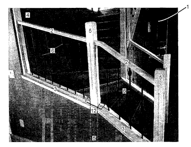
[00044] Figure 1 generally shows a portion of a typical staircase within a
home. The
staircase has a balustrade (1) including an upper railing (2) and a lower
railing (3). Both the
upper and lower railings (2, 3) are secured to a side wall (4) at one end and
to a newel post (5) at
the other end. Multiple newel posts (5) are used at the start, and at points
of vertical and
directional transition to provide backbone strength to the balustrade (1).
Balusters (6) between
the upper and lower railings (2, 3) provide safety and support. The underside
of the staircase is
often hidden or covered by a stairway wall (7). The stairway wall (7) is
formed of a top plate
7
CA 02857824 2014-07-23
(8), a base plate (9), vertical studs or planks of wood (10) between the top
plate (8) and base
plate (9), and blocking boards (11) between each stud (10) (shown in phantom).
[00045] Figure 2 generally shows another portion of the staircase of Figure
1, including a
landing (13) or floor between flights of stairs, and a ceiling wall (14) which
conceals the top
plate (8), base plate (9), studs (10), and ceiling joists (not shown).
[00046] Newel posts (5) are typically anchored only at their lower ends,
but must
withstand tremendous lateral forces applied upon the upper railing (2) such
that they can become
loose and unstable over time. The present invention (diagrammatically shown in
phantom at 12
in Figures 1 and 2) enables proper installation and secure, reliable mounting
of the newel posts
(5), thereby reinforcing the strength and stability of the balustrade (1).
Further, the invention
(12) may be completely concealed behind the stairway wall (7) (Figure 1) or
ceiling wall (14)
(Figure 2), thus ensuring that the staircase remains esthetically pleasing.
[00047/ In one embodiment, the invention comprises a bracket for
constructing a
balustrade comprising: a receiving member configured to receive and secure a
post therein; and a
pivoting member pivotally mounted to the receiving member and configured to be
attached to a
top plate of a stairway wall to orient the post within the top plate at a
desired position, angle, or
both.
[00048] In one embodiment, the invention comprises a method of stabilizing
a balustrade
comprising the steps of forming a gap within the top plate for installing the
bracket; sliding the
bracket into position within the gap; fastening the bracket onto the top
plate; preparing the post
to fit into the bracket; inserting and attaching the prepared post within the
bracket at a desired
position, angle, or both.
[00049] Figure 3 generally shows one embodiment of the bracket (12) of the
present
invention in use in construction of a typical balustrade (1). One side of the
wall (7) has been
removed to display the bracket (12) and post (5) following installation. The
bracket (12)
comprises a receiving member (16) and a pivoting member (18), The receiving
member (16) is
8
CA 02857824 2014-07-23
configured to allow the insertion of the post (5). The pivoting member (18) is
pivotally mounted
to the receiving member (16) and is configured to be attached onto ends (20)
of the top plate (8)
of the wall (7), thereby suspending the receiving member (16) between the ends
(20) of the top
plate (8), The receiving member (16) and pivoting member (18) substantially
align together in a
manner to form and share an opening (22) extending therethrough for receiving
the post (5).
[000501 Figures 4-13 show the bracket (12) removed from within the wall
(7). The
receiving member (16) comprises upstanding walls (24, 26, 28, 30) which
project upwardly and
define the opening (22). In one embodiment, the receiving member (16)
comprises a front wall
(24), a rear wall (26), a first side wall (28), a second side wall (30), an
open first end (32) and an
open second end (34). The front wall (24) opposes the rear wall (26). The
first side wall (28)
opposes the second side wall (30). At one edge, the front and rear walls (24,
26) merge with the
first side wall (28). At the other edge, the front and rear walls (24, 26)
merge with the second
side wall (30). The open first and second ends (32, 34) together facilitate
insertion of the post (5)
through the opening (22).
[000511 In one embodiment, the front wall (24) is sized to be lower
vertically than the rear
wall (26), first side wall (28), and second side wall (30), as shown for
example in Figure 4.
[000521 The rear wall (26) is connected to the side walls (28, 30)
(Figure 5). The rear wall
(26) is sized to be higher vertically than the front wall (24), as shown for
example in Figure 4.
[000531 The first and second side walls (28, 30) are configured to be
substantially
identical to each other, as best shown when the bracket (12) is viewed from
the side (Figures 6,
7, 11 and 12). The first and second side walls (28, 30) connect the front wall
(24) to the rear wall
(26). The first and second side walls (28, 30) are sized to be the same height
vertically as the
rear wall (26), but are cut away at the top corners (36) facing the front wall
(24) (Figures 11-12).
The top cut-away corners (36) are generally complementary to the vertical
height of the front
= wall (24). The corners (36) are cut away to allow the pivoting member
(18) to rotate easily and
freely without protruding corners hindering its movement. In one embodiment,
the cut-away
9
CA 02857824 2014-07-23
corners (36) allow the pivoting member (18) to rotate to an angle of about 45
relative to the
receiving member (16) (Figure 13).
[00054] One or more of the front wall (24), rear wall (26), and side walls
(28, 30) may
define one or more apertures (38) through which attachment means may be
inserted to secure the
post (5) to the receiving member (16) (Figures 4-7 and 9-13). Suitable
attachment means
include, but are not limited to, screws, pins, rivets, bolts, and other types
of fasteners. It is
contemplated that the number (density), size (diameter), shape, and
positioning of the apertures
(38) for an embodiment of the bracket (12) may vary. Apertures (38) may be
made using a
number of methods known to those skilled in the art, including but not limited
to drilling.
[00055] The shape of the receiving member (16) is not limited to that of
the present
example, but may variously be changed, for example, into a square,
parallelogram, or the like. In
one embodiment, the receiving member (16) of the bracket (12) may be
substantially
rectangular-shaped comprising planar front, rear and side walls (24, 26, 28,
30).
[00056] The pivoting member (18) comprises a pair of arms (40), a first
mounting plate
(42), a second mounting plate (44), and a gap (46) (Figures 8-9). The arms
(40) are configured
to be substantially identical to each other, as best shown when the bracket
(12) is viewed from
the top (Figures 8-9) or the side (Figures 11-12). The arms (40) are oriented
opposed and
parallel to each other, as best shown when the bracket (12) is viewed from the
top (Figures 8-9).
The arms (40) are connected at their ends (48) to the first and second
mounting plates (42, 44).
In one embodiment, each arm (40) is oriented perpendicularly to the first and
second mounting
plates (42, 44) (Figures 6, 7, and 11-13), The arms (40) and mounting plates
(42, 44) together
define-the gap (46) (Figures 8-9). The gap (46) extends past the front wall
(24) and the rear wall
(26). The gap (46) defined by the arms (40) and mounting plates (42, 44) is
sized to receive and
accommodate the receiving member (16), In one embodiment, the gap (46) is
sized to extend
past the front wall (24) and rear wall (26) of the receiving member (16). The
dimensions of the
gap (46) are thus dictated by the size of the receiving member (16).
CA 02857824 2014-07-23
[00057] In one embodiment, each arm (40) is substantially rectangular-
shaped with a
bottom cut-away corner (50) at each end (48) (Figures 6, 7 and 11-13). The cut-
away corners
(50) substantially conform to the ends (20) of the top plate (8) to facilitate
the installation of the
bracket (12) (Figure 3). The shape of the cut-away corners (50) is not limited
to that of the
present example, but may variously be changed, for example, straight or
curved. In one
embodiment, the cut-away corners (50) are curved. During installation of the
bracket (12), the
curved cut-away corners (50) minimize the amount of preparation required for
the ends (20) of
the top Plate (8) and facilitate insertion of the post (5).
[0005$1 The arm (40) protrudes past the edges of the side wall (28, 30) to
allow the
pivoting member (18) to be mounted over the receiving member (16). In one
embodiment, the
arm (40) has a length greater than the width of the side wall (28, 30) (Figure
8).
[00059j The first and second side walls (28, 30) define opposed bores (52)
positioned at
the top of the side walls (28, 30) and adjacent to the top cut-away corners
(36) (Figure 10). The
arms (40) define opposed throughholes (54) which align with the corresponding
bores (52) of the
side walls (28, 30) to allow attachment means to extend therethrough to
pivotally mount the
pivoting member (18) to the receiving member (16) (Figures 11-12). In one
embodiment, the
throughholes (54) and bores (52) are positioned along the top edges of the
arms (40) and side
walls (28, 30) respectively, such that the pivoting member (18) is mounted to
the receiving
member (16) at the top edges of the side walls (28, 30). It is contemplated
that the throughholes
(54) and corresponding bores (52) may vary in position to allow the pivoting
member (18) to be
mounted in any desired position along the side walls (28, 30). Suitable
attachment means
include, but are not limited to, screws, pins, rivets, bolts, and other types
of fasteners.
[000601 In addition, the first and second side walls (28, 30) define
opposed curved slots
(56) positioned below the bores (52) (Figures 10-12). The slots (56) curve in
a pathway from
beneath the bores (52) upward toward the top cut-away corners (36). The arms
(40) define
opposed openings (58) which are positioned at the bottom edge of the =arms
(40), and at ,an angle
beneath the throughholes (54) (Figures 11-12). The openings (58) align with
and follow the
pathway of the curved slots (56) as the pivoting member (18) is moved from a
resting position
CA 02857824 2014-07-23
wherein the pivoting member (18) is not tilted, to an actuating position
wherein the pivoting
member (18) is tilted in the direction of the front wall (24). During use,
attachment means are
inserted through the openings (58) of the arms (40) and the curved slots (56)
of the side walls
(28, 30) to position the bracket (12) at any desired position, angle, or both.
Suitable attachment
means include, but are not limited to, screws, pins, rivets, bolts, and other
types of fasteners.
[000611 A stopper or protuberance (60) is disposed on the outer surface of
one of the side
walls (28, 30) and projects outwardly with respect to the side wall (28, 30)
(Figures 3 and 6).
The stopper (60) may comprise a rivet or a portion of cold rolled steel which
is fixed to the side
wall (28) by welding or other techniques known to those skilled in the art.
The stopper (60)
restrains the movement of the pivoting member (18) by protruding outwardly to
abut the arm
(40) of the pivoting member (18), thereby preventing the pivoting member (18)
from tilting in
the direction of the rear wall (26). In one embodiment, the stopper (60)
restrains the pivoting
member (18) substantially "flat" or horizontal relative to the receiving
member (16). In one
embodiment, the pivoting member (18) is positioned at an angle of about 90
relative to the
receiving member (16) (Figures 4-7),
[000621 The first and second mounting plates (42, 44) are substantially
rectangular-
shaped. However, the shape of the first and second mounting plates (42, 44) is
not limited to that
of the present example, but may variously be changed, for example, into a
square or the like.
000631 In one embodiment, the first and second mounting plates (42, 44)
define one or
more apertures (62) and/or one or more elongate slots (64) through which
attachment means may
be inserted to secure the bracket (12) onto the top plate (8) (Figures 8-12),
Suitable attachment
means include, but are notlimited to, screws, pins, rivets, bolts, and other
types of fasteners. It is
contemplated that the number (density), size (diameter), shape, and
positioning of the apertures
(62) and slots (64) for an embodiment of the bracket (12) may vary. Apertures
(62) and slots
(64) may be made using a number of methods known to those skilled in the art,
including but not
limited to drilling and machining.
12
CA 02857824 2014-07-23
[00064] In one embodiment, the first mounting plate (42) is configured
differently from
the second mounting plate (44). In one embodiment, the first mounting plate
(42) defines a pair
of apertures (62), a pair of elongate slots (64), and a window (66), The
apertures (62) and slots
(64) are positioned at the corners of the first mounting plate (42), with the
slots (64) being
positioned at the edge of the first mounting plate (42) adjacent to the arms
(40). The apertures
(62) receive attachment means to secure the bracket (12) onto the top plate
(8). The front wall
(24) defines corresponding front wall slots (68) (Figures 4 and 10). The first
mounting plate
slots (64) facilitate the insertion of attachment means at an angle to extend
through the first
mounting plate (42), top plate (8), front wall slots (68), and post (5).
[000651 The window (66) is positioned near or at the center of the first
mounting plate
(42). The front wall (24) defines a corresponding window (70) (Figures 4 and
10). The
windows (66, 70) are sized to receive a leg bolt or heavy screw. The leg bolt
is drilled through
the top plate (8) in a manner such that the leg bolt extends through the
window (66) of the first
mounting plate (42), the top plate (8), the window (70) of the front wall
(24), and into the post
(5) in order to secure the post (5) at the desired angle or position. The
shape of the windows (66,
70) is not limited to that of the present example, but may variously be
changed, for example, into
a square, parallelogram, circular or the like. In one embodiment, the windows
(66, 70) may be
substantially rectangular-shaped. in one embodiment, the window (70) of the
front wall (24) is
larger than the window (66) of the first mounting plate (42) to facilitate
positioning of the leg
bolt at various angles more easily.
[000661 In one embodiment, the second mounting plate (44) defines an
aperture (62)
positioned centrally at the edge of the plate (44) adjacent to the arms (40),
and elongate slots (64)
positioned at the corners of the plate (44). The aperture (62) receives
attachment means to
secure the bracket (12) onto the top plate (8). The slots (64) facilitate the
insertion of attachment
means at an angle through the mounting plate (44) and top plate (8).
[000671 The pivoting member (18) may be pivoted relative to the receiving
member (16),
but any pivotal adjustment possible in the pivoting member (18) is limited by
the receiving
member (16) and stopper (60). The inclination or pitch angle of the pivoting
member (18) is
13
CA 02857824 2014-07-23
adjustable within the physical constraints of the receiving member (16), but
no side-to-side
rotation, commonly referred to as the yaw angle, is possible. In one
embodiment, the inclination
ranges from between about 45 to about 90 . The pivoting member (18) is
pivotally mounted to
the receiving member (16) to enable two positions of movement, namely a
resting position and
an actuating position.
[00068] In the resting position, the pivoting member (18) is resting
substantially "flat" or
horizontal relative to the receiving member (16). In one embodiment, the
stopper (60) prevents
the pivoting member (18) from tilting in the direction of the rear wall (26)
such that the pivoting
member (18) is positioned at an angle of about 90 relative to the receiving
member (16)
(Figures 6-8).
[00069] The pivoting member (18) is movable from the resting position
wherein the
pivoting member (18) is not tilted, to the actuating position wherein the
pivoting member (18) is
tilted in the direction of the front wall (24) during use (Figures 3 and 11-
13). The top cut-away
corners (36) of the first and second side walls (28, 30), and the lower
vertical height of the front
wall (24) compared to the rear and side walls (26, 28, 30) thereby allow the
pivoting member
(18) to rotate easily and freely without protruding comers or walls hindering
its movement. As
shown in Figure 3, the pivoting member (18) is thus pivoted at an angle
relative to the receiving
member (16) to align with the ends (20) of the top plate (8) to hold the post
(5) in the desired
position, thereby stabilizing the balustrade (1). In one embodiment, the
pivoting member (18) is
positioned between an angle of about 45 to about 90 relative to the
receiving member (16).
[00070] The dimensions are not essential to the invention and are dictated
by the
dimensions of the post (5). The dimensions of the bracket (12) may be
increased or decreased as
may be required to satisfy any particular design objectives; for example, the
bracket (12) may be
available in a variety of dimensions. In one embodiment, the bracket (12) has
a height of about 6
inches, and a width of about eleven inches, In one embodiment, the receiving
member (16) has a
height of about six inches, and a width of about 3.5 inches. In one
embodiment, the pivoting
member (18) has a height of about one inch, and a width of about eleven
inches.
14
CA 02857824 2014-07-23
[00071] The bracket (12) can be constructed from any material or
combination of
materials having suitable properties such as, for example, mechanical strength
and ease of
welding. Suitable materials include, but are not limited to, aluminum, steel,
stainless steel, or
other appropriate metals. Aluminum is preferable since it does not rust or
corrode, and is softer
and cheaper than steel, hence easier and inexpensive for manufacturing the
bracket (12) (Figures
8713). If steel is used for its construction, the bracket (12) is coated with
a rust-inhibiting primer
(Figures 4-7).
[00072] The receiving member (16) may be formed as a single, integral unit
or "box"
combining the front wall (24), rear wall (26), and side walls (28, 30), with
the side walls (28, 30)
being machined to form the cut-away corners (36). Alternatively, the walls
(24, 26, 28, 30) may
be formed independently and welded together to form a single, integral unit.
In one
embodiment, a single piece is bent to form the rear (26) and side walls (28,
30), with the finished
front wall (24) (i.e., including any apertures (38, slots (68) and window
(70)) then being welded
to the side walls (28, 30).
[00073] The pivoting member (18) may be formed as a single, integral unit
combining the
arms (40) and mounting plates (42, 44) in a planar form or flat sheet, with
the arms (40) then
being folded or bent over. Alternatively, the arms (40) and mounting plates
(42, 44) are
manufactured separately as components which are welded together. Any apertures
(38, 62),
bores (52), throughholes (54), openings (58), slots (56, 64), and windows (66,
70) may be made
in the appropriate components using any hole- or window-making operations
known to those
skilled in the art, including but not limited to drilling, reaming, tapping,
boring, machining, and
the like.
[00074] In general, the bracket (12) requires few components, making the
bracket (12)
amenable to rapid assembly and minimizing expense in manufacturing.
Alternatively, the
bracket (12) may be formed using waterj et cutting which involves use of a
water jet cutter to
fabricate the components of the bracket (12).
CA 02857824 2014-07-23
[000751 The installation of the bracket (12) can be performed easily by
building
contractors, construction companies, and home builders. The bracket (12)
enables the
positioning and placing of the posts (5), negating the need to rely upon studs
and floor joists.
The bracket (12) can be used to secure the post (5) in any desired location
and/or angle within
the wall (7).
[000761 In operation, the bracket (12) is installed within a stairway wall
(7) formed of a
top plate (8), a base plate (9), and sides (72). The top plate (8) typically
comprises dimensional
lumbar such as, for example, a two-by-four board. The top plate (8) is first
prepared by
measuring and marking a section to accommodate the bracket (12) where the post
(5) is to be
positioned (Figure 14A). The section is cut away, thereby leaving a gap (74)
into which the
bracket (12) can be installed (Figures 14B-C). In one embodiment, the gap (74)
has a width of
about 5". The faces of the top plate (8) which line the gap (74) are shaved
down to form notches
(76). In one embodiment, the faces are shaved down by about 1/8" (Figure 14C).
The notches
(76) are complementary to the shapes of the first and second mounting plates
(42, 44) to seat the
mounting plates (42; 44). The corners of the top plate (8) are trimmed to form
angled edges (78)
which are complementary to the cut-away corners (50) of the arms (40) (Figure
14D).
[00077] The bracket (12) is slid into position within the gap (74) (Figure
14E).
Attachment means are inserted through the apertures (62) of the first and
second mounting plates
(42, 44) to secure the plates (42, 44) within the notches (76) formed in the
top plate (8) (Figure
14F). A pilot hole is bored through each side (72) of the wall (7) by pushing
a screw through the
elongate slot (56) of each side wall (28, 30) and the opening (54) of each arm
(40).
[00078] The post (5) is sized or trimmed to fit within the receiving member
(16) of the
bracket (12), and is cut to the desired length (Figure 14G), The post (5) is
inserted into the
receiving member (16) of the bracket (12) (Figure 14H). Figure 14H also shows
an additional
bracket (12) since the top plate (8) may include more than one bracket (12)
for use with multiple
posts (5). Posts (5) may be secured substantially horizontal or at any degree
of angle (for
example, up to 45 ) within the wall (7). The post (5) is secured at the
desired height into the
receiving member (16) using attachment means such as screws. The post (5) is
levelled while
16
CA 02857824 2014-07-23
screws are drilled through the elongated slots (64) of the first mounting
plate (42) into the post
(5) (Figure 141). Using the pilot holes, screws are drilled into the desired
position through the
sides (72) of the wall (7), thereby reducing any forward or backward movement
of the post (5)
and securing the post (5) within the receiving member (16) (Figure 14J).
[000791 The leg bolt or heavy screw can be used to facilitate anchoring the
post (5) at the
desired angle, position, or both. A pilot hole for either the leg bolt or the
heavy screw is drilled
through the window (66) of the first mounting plate (42), the top plate (8),
the window (70) of
the front wall (24), and the post (5) (Figure 14K). The leg bolt or heavy
screw is then drilled
through the pilot hole to extend through the window (66) of the first mounting
plate (42), top
plate (8), window (70) of the front wall (24), and into the post (5) (Figure
14L).
[00080.1 The balustrade (1) is then completed in a manner well known to
those skilled in
the art (Figure 14M-N), Embodiments of the bracket (12) in use are shown for
example, in
Figures 1-2, The present invention (diagrammatically shown in phantom at 12 in
Figures 1 and
2) enables proper installation and secure, reliable mounting of the newel
posts (5), thereby
reinforcing the strength and stability of the balustrade (1). Further, the
invention (12) may be
completely concealed behind the stairway wall (7) (Figures 1 and 14N) or
ceiling wall (14)
(Figure 2), thus ensuring that the staircase remains esthetically pleasing.
[000811 It should be apparent, however, to those skilled in the art that
many more
modifications besides those already described are possible without departing
from the inventive
concepts herein. The inventive subject matter, therefore, is not to be
restricted except in the
spirit of the disclosure. Moreover, in interpreting the disclosure, all terms
should be interpreted
in the broadest possible manner consistent with the context. In particular,
the terms "comprises"
and "comprising" should be interpreted as referring to elements, components,
or steps in a non-
exclusive manner, indicating that the referenced elements, components, or
steps may be present,
or utilized, or combined with other elements, components, or steps that are
not expressly
referenced.
17
CA 02857824 2014-07-23
References
[000821 All publications mentioned herein are incorporated herein by
reference (where
permitted) to disclose and describe the methods and/or materials in connection
with which the
publications are cited. The publications discussed herein are provided solely
for their disclosure
prior to the filing date of the present application. Nothing herein is to be
construed as an
admission that the present invention is not entitled to antedate such
publication by virtue of prior
invention. Further, the dates of publication provided may be different from
the actual
publication dates, which may need to be independently confirmed.
Bobrowski, L.G. Guardrail assembly. United States Patent No. 3,342,457,
published September
19, 1967.
Burt, KT., Sherstad, M.C. and Irick, J.D. Bracket for supporting attachment of
the end of a
railing member to a vertical member. United States Patent Application
Publication No.
2013/0175488 Al, published July 11,2013,
Dotsey, M. Rail assembly having a baluster swing bracket. United States Patent
No. 8,376,321,
published February 19, 2013.
Erwin, R.D. Rail-to-post mounting bracket. United States Patent No. 6,471,192,
published
October 29, 2002.
Erwin, R.D. Mounting bracket for railing. United States Patent No. 6,527,469,
published March
4, 2003.
Erwin, R.D. Fence bracket. United States Patent No. 6,557,831, published May
6, 2003.
Fletcher, R.J. and Williams, E.J. Fencing structures. UK Patent Application
No. GB 2,005,325
A, published April 19, 1979.
18
CA 02857824 2014-07-23
Ford, G.N. Arrangement and method for connecting fence sections. International
Publication No.
WO 2008/018964, published February 14, 2008.
Fuoco, M. Temporary structure bracket. United States Patent No. 7,377,491,
published May 27,
2008.
Heinz, D.E. Fence angular connector assembly. United States Patent No.
4,923,176, published
May 8, 1990.
Hentzschel, W.G. Fence rail bracket. United States Patent No, 5,186,571,
February 16, 1993.
Hocking, W.P. Anchoring device, United States Patent No. 4,599,010, published
July 8, 1986.
Leone, N. Bracket for a fencing system. United States Patent No, 5,961,242,
published October
5, 1999.
Milner, W., Diener, R. and Rose, D. Connection fixture. International
Publication No. WO
2009/126989, published October 22, 2009.
Newlin, F. Coupling. United States Patent No. 1,070,165, published August 12,
1913.
Otte, D.R. and Krueger, S.E. Railing construction. United States Patent No.
4,919,394, published
April 24, 1990.
Platt, R.E. Unitary rail mounting bracket. United States Patent Application
Publication No.
2007/0187662, published August 16, 2007.
Schultz, D.H., Mattson, S.W. and Heinz, D.E. Railing construction, United
States Patent No.
4,951,925, published August 28, 1990.
19
CA 02857824 2014-07-23
Sneith, J.M. Baluster bracket assembly. United States Patent Application
Publication No.
2013/0214228, published August 22, 2013.