Note: Descriptions are shown in the official language in which they were submitted.
CA 02858046 2014-07-31
AGRICULTURAL TRACTOR WITH AIR CONDITIONING COMPRESSOR DRIVE
This invention relates an agricultural tractor such as a tractor, swather
tractor or combine harvester and particularly to an improved arrangement for
driving
the air conditioning compressor for the air conditioning system in the cab. In
particular the invention relates to an improved air conditioning system in
which the
compressor of the air conditioning system is powered by the engine cooling
fan.
BACKGROUND OF THE INVENTION
Conventionally the air conditioning compressor of an agricultural
tractor is driven by a belt from the accessory drive pulley.of the engine
SUMMARY OF THE INVENTION
According to the invention therefore there is provided an agricultural
tractor comprising:
a frame extending in a longitudinal direction the tractor;
a plurality of rotatable ground wheels connected to the frame to convey
the frame over the ground, including drive wheels operable to drive the
tractor in a
forward working direction along the longitudinal direction of the tractor;
an operator cab carried on the frame;
an engine mounted in an engine compartment on the frame at a
position longitudinally spaced from the cab;
a cooling assembly at the engine compartment for cooling the engine;
a hydraulic motor driving a fan on the cooling assembly;
CA 02858046 2014-07-31
2
an air conditioning system arranged for cooling the cab of the tractor
including an air conditioning compressor;
wherein the air conditioning compressor is driven from the hydraulic
motor.
In one arrangement, dependent on the geometry of the system, the air
conditioning compressor can be driven through a pulley arrangement driven by
the
shaft of the hydraulic motor.
In another arrangement, the air conditioning compressor can be
mounted on a shaft of the hydraulic motor and is driven directly thereby.
In accordance with an important aspect of the invention there is
provided a clutch for disconnecting drive from the hydraulic motor to the air
conditioning compressor, the clutch being controlled by a. control system of
the
tractor. This allows the drive to the air conditioning compressor to be halted
when
required.
Preferably the control system is arranged to operate the clutch in
response to a signal from the control system activating a reverse drive cycle
of the
cooling fan to prevent reverse rotation of the air conditioning compressor
when the
fan on the cooling system is reversed for cleaning the cooling system
Preferably the fan on the cooling system is closer to an evaporator coil
of the air conditioning system than is an accessory drive pulley of the
engine.
Preferably the air conditioning compressor is driven by the hydraulic
motor at a rate which is dependent on engine cooling requirements so that the
drive
=
CA 02858046 2014-07-31
3
to the air conditioning compressor is independent of engine speed.
Thus the air conditioning compressor can be driven at a reduced rate
during periods of low heat loads so that a thermostat can provide reasonable
compressor cycle times and prevent rapid on and off cycling of the compressor.
Thus the air conditioning compressor can be driven at an increased
rate during periods of high heat loads due to the higher speed of the cooling
fan.
The advantage to powering and mounting the compressor of the air
conditioning system within the housing of the radiator and driven directly, or
indirectly of the shaft of the fan is that the lines of the air conditioner
can be shorter
from evaporator to compressor and compressor to condenser resulting in less
refrigerant loss over time and reduced cost. Also allows the compressor to be
independent of the engine, thereby using common parts, being the same drive
system and hoses for all engines. As well as higher heat loads caused by high
ambient heat will cause the compressor to turn faster when engaged. Also the
compressor RPMs will be reduced during periods of low heat loads caused by low
ambient heat reducing the need for an electronic thermostat to prevent the
compressor from switching on and off rapidly.
BRIEF DESCRIPTION OF THE DRAWINGS
One embodiment of the invention will now be described in conjunction
with the accompanying drawings in which:
Figure 1 is a schematic plan view of one type of agricultural equipment,
CA 02858046 2014-07-31
4
this example being a swather.
Figure 2 is a cross sectional view of the cooling system of one
embodiment of the present invention.
Figure 3 is a cross sectional view of another embodiment of the
present invention.
Figure 4 is a cross sectional view of a third embodiment of the present
invention.
In the drawings like characters of reference indicate corresponding
parts in the different figures.
DETAILED DESCRIPTION
The present invention can be utilized in any commonly known
agricultural machine such as a combine harvester, tractor or swather. In this
embodiment the present invention is shown within a swather but can vary widely
in
accordance with requirements, as is well know to a person skilled in this art.
A swather 1 includes an engine 3 carried on a frame 5, adjacent a first
end 7. The frame is carried on a first pair of driven ground wheels 9 and a
second
pair of non-driven castor wheels 11. The driven wheels are mounted on suitable
supports 13 which support the ground wheels from the frame. The driven ground
wheels are driven by a hydraulic motor carried on the support which receives
hydraulic fluid under pressure from a supply line that drives the ground wheel
at a
rate of rotation dependant upon the rate of flow of the hydraulic fluid.
The castor wheels are mounted on conventional castors 15 which
CA 02858046 2014-07-31
swivel about a castor pin 17. The ground wheels are non driven and are simply
mounted in a supporting bracket 20 which can pivot around the castor pin so
that the
castor wheels follow the movement of the vehicle as controlled by the driven
wheels.
Thus the speed of the vehicle over the ground is controlled by the rate of
rotation of
5 the wheels and steering is controlled by a differential in speed between
the wheels.
The frame is shown only schematically since this can vary widely in
accordance with requirements, as is well known to a person skilled in this
art. At the
driven end 11A of the frame is mounted suitable supports 21 and 22 for
carrying a
header 23A. Again these elements are well known to persons skilled in this art
and
various different designs can be used. Thus the support elements 21, 22 on the
header carried thereby are shown only schematically. Various different types
of
headers can be used including disc type cutters or sickle knife cutters. The
width of
the header can vary considerably depending upon the type of crop and the
cutting
system employed. The header is preferably carried on the tractor rather than
on
separate supports and the tractor includes a lifting mechanism schematically
indicated at 23 operable to raise and lower the header on the tractor between
different working positions, and between working positions and a raised
position
cleared from the ground for moving the header over the ground when not in
working
position.
The tractor includes the engine 3 carried on the frame 11 adjacent a
second end 11B of the frame. The engine is arranged to drive a series of pumps
25,
26 and 27 for generating pressurized hydraulic fluid for driving the various
CA 02858046 2014-07-31
components of the tractor. Separate pumps can be used as shown or single pump
can be used with the hydraulic fluid under pressure generated thereby being
separated into separate controlled fluid paths for operating the various
components,
or in a parallel arrangement such as on the M-series windrowers manufactured
by
the present assignee. The operator console 31 may be of the type described
in
U.S. Patent No. 7,159,687 of the present assignee, where the console is
arranged to
be rotatable about an upright axis between a first position (illustrated in
Figure 1)
where the seat faces the driven end 11A of the machine and a second position
(not
shown) in which the seat faces the engine end 11B of the machine. The first of
these
positions is known herein as a "field" or "cab forward" mode where the
operator
console faces the header 23A for use of the same in the field with the machine
driven in the illustrated working direction F. The other position may be known
as a
"transport" or "engine forward" mode, where the operator console faces the
engine
end 11B of the machine for road transport of the machine by driving of same in
an
opposite direction in which engine leads the cab.
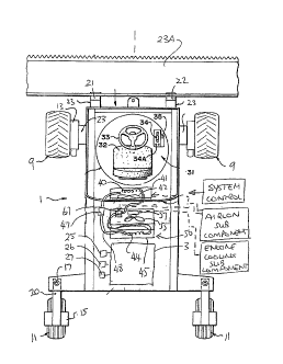
A radiator assembly 50 mounted within the engine compartment is
arranged to cool the engine by way of a coolant flowing through a cooling
circuit.
The radiator assembly has a housing or shroud 52 which is arranged to house
the
components of the radiator assembly. As commonly known to one skilled in the
art,
the radiator provides cooling to the engine by driving a fan 55. In this
example, the
fan is driven by a hydraulic motor 57 mounted on a rotatable shaft 59. The fan
is
mounted on the shaft so as to be driven directly by the motor. As an
alternative it
CA 02858046 2014-07-31
7
could also be indirectly driven (e.g. by belt) from the motor.
An air conditioning system for the cab includes an evaporator coil 40
within a housing 41 in the cab with a fan 42 arranged to drive air over the
coil 40 into
the cab for cooling the operator. A condenser coil 44 is located at a location
45 on
the exterior of the tractor and cooled by the fan 55 using outside air. A
compressor
67 is provided with a valve 47 in a circuit to complete the conventional air
conditioning system. The present invention relates to an improved arrangement
for
driving the compressor 67 of the air conditioning circuit 48.
The condenser coil 44 is provided as part of the engine cooling system
so that it is cooled by the same fan 55 as the engine cooling system 50. As
shown
these components are mounted directly behind the cab in front of the engine.
Thus
the condenser coil 44 is located closely adjacent the evaporator coil 40 and
the
circuit 48 has very short leads since the compressor 67 is located between the
coils.
In a first embodiment of the present invention, as illustrated in figure 2,
a pulley 61 is mounted on the shaft 59, between the motor and the fan at a hub
62 of
the fan 55. The pulley 61 is arranged to be driven by the motor using
hydraulic
power taken from the engine which drives one of the pumps 25, 26, 27 which
provides oil to the motor at the same RPM as the fan 55. A second pulley 63 is
mounted within the housing 52 adjacent the first pulley 61 and the pulleys are
connected to each other by a belt 65. A compressor 67 of an air conditioning
system, as commonly known to someone skilled in this art, is mounted to the
second
pulley within the radiator housing. The compressor 67 therefore is arranged to
be
CA 02858046 2014-07-31
8
powered by the fan motor 57.
In a second embodiment of the present invention, as illustrated in
figure 3, the first pulley 61A is mounted on the shaft 59 but behind the
hydraulic
motor 57 in relation to the fan 55. The second embodiment is similar is design
to the
first embodiment in that the first pulley is connected to a second pulley 63A
through
a belt 65A. The second pulley is arranged to provide power to the compressor
67A
of the vehicle's air conditioning system.
In a third embodiment of the present invention, as illustrated in figure 4,
the compressor 67B is mounted directly on the shaft 59 of the motor 57 such
that the
compressor is driven by the shaft 59, without the use of pulleys.
The tractor includes an electronic control system 100 which operates
all control aspects of the tractor including various operator inputs and
sensor inputs
well known to a person skilled in this art. This system includes an air
conditioning
control sub-component 101 which controls the air conditioning system in
response to
operator input within the cab and temperature sensors within the cab. The
system
100 also includes an engine cooling subcomponent 102 which controls the speed
of
the fan 55 dependent on engine cooling requirements and controls a reverse fan
cycle for periodic cleaning of the radiator by reverse drive to the fan to
blow off
contaminants. There is also provided a clutch 70 for disconnecting drive from
the
hydraulic motor to the air conditioning compressor 67, the clutch being
controlled by
the control system 100, 101 of the tractor. This allows the drive to the air
CA 02858046 2014-07-31
9
conditioning compressor to be halted when required by the airconditioning
control
system.
The control system 101 is arranged also to operate the clutch 70 in
response to a signal from the control system 102 activating a reverse drive
cycle of
the cooling fan to prevent reverse rotation of the air conditioning compressor
when
the fan on the cooling system is reversed for cleaning the cooling system.
The air conditioning compressor 67 is driven by the hydraulic motor 57
at a rate which is dependent on engine cooling requirements as determined by
the
control system 102 so that the drive to the air conditioning compressor is
independent of engine speed.
Thus the air conditioning compressor 67 is driven at a reduced rate
during periods of low heat loads so that there is no need for an electronic
thermostat
used to prevent rapid on and off cycling of the compressor.
Thus the air conditioning compressor 67 is driven at an increased rate
during periods of high heat loads due to the higher speed of the cooling fan.
The fan 57 on the cooling system is closer to the evaporator coil 40 of
the air conditioning system than is the accessory drive pulley of the engine
so that
the lines of the circuit 48 are reduced in length.