Note: Descriptions are shown in the official language in which they were submitted.
CA 02858056 2014-07-30
BATTERY CHARGER
TECHNICAL FIELD
The application relates generally to devices which supply electrical power
and, more particularly, to a battery charger and battery charging system.
BACKGROUND OF THE ART
Electrical power is supplied to all manner of portable devices. It is known,
for
example, to use a vehicle's electrical supply to power the batteries of
portable devices
such as mobile phones. However, many current devices which use the vehicle's
electrical supply are cumbersome, and do not secure the portable device, or
its battery,
in place within the vehicle as it is driven. Furthermore, many current devices
are limited
to being used in the vehicle because they must be plugged into the vehicle's
12 V
battery-power system, and are thus incapable of supplying electrical power
away from
the immediate vicinity of the vehicle.
SUMMARY
In one aspect, there is provided a portable battery charger, comprising: a
body having an outer surface extending between a top surface and a bottom
surface,
the outer and bottom surfaces of the body shaped and sized to be insertable
into a
receptacle and secured therein by a friction fit; a battery-charging slot
extending into the
body from the top surface, the battery-charging slot in use receiving a
battery to be
charged and transferring electrical power thereto; at least one power input
disposed on
the top surface of the body, the at least one power input in use transferring
electrical
power to the body; and an energy storage housed within the body and in
electrical
communication with the battery-charging slot and the at least one power input.
In another aspect, there is provided a battery charging system, comprising: a
portable battery charger, comprising: a body having an outer surface extending
between a top surface and a bottom surface, the outer and bottom surfaces of
the body
shaped and sized to be insertable into a receptacle and secured therein by a
friction fit;
a battery-charging slot extending into the body from the top surface, the
battery-
charging slot in use receiving a battery to be charged and transferring
electrical power
1
CA 02858056 2014-07-30
thereto; at least one power input disposed on the top surface of the body, the
at least
one power input in use transferring electrical power to the body; and an
energy storage
housed within the body and in electrical communication with the battery-
charging slot
and the at least one power input; and a power adapter having an adapter body
defining
a mounting bracket removably mountable to the body of the battery charger, the
mounting bracket having a locking mechanism in use engaging the body and a
power
output mountable to the at least one power input of the battery charger to
supply
electrical power thereto, the power adapter also having a power socket
disposed on the
adapter body to receive electrical power from an external power source.
DESCRIPTION OF THE DRAWINGS
Reference is now made to the accompanying figures in which:
Fig. 1A is a perspective view of a battery charger, according to an
embodiment of the present disclosure;
Fig. 1B is another perspective view of the battery charger of Fig. 1A;
Fig. 1C is a top view of the battery charger of Fig. 1A;
Fig. 2 is a perspective view of a battery charging system having a battery
charger as shown in Fig. 1A and a power adapter, according to another
embodiment of
the present disclosure; and
Fig. 3 is a perspective view of the power adapter of Fig. 2.
DETAILED DESCRIPTION
Figs. 1A and 1B illustrate a portable battery charger 10 for charging a
battery
12. The battery charger 10 is portable (mobile) such that it can be used to
recharge a
battery, even when the battery charger 10 is not connected to a power source
(e.g.
120V AC power or 12V DC power, for example). The battery charger 10
accordingly
receives and stores electrical power, and transfers it to the battery 12, to
thereby
recharge the rechargeable battery 12, when the two are connected. This enables
the
battery 12 to be recharged in any desired remote location, even when other
power
sources are not readily nearby.
2
CA 02858056 2014-07-30
The battery 12 is a rechargeable battery which supplies electrical power to
any suitable device, such as small electronic devices and/or appliances for
example.
Some non-limiting examples of batteries 12 within the scope of the present
disclosure
include nickel¨cadmium (NiCd), nickel¨zinc (NiZn), nickel metal hydride
(NiMH), and
lithium-ion (Li-ion) cells.
The battery charger 10 is portable and can therefore be transported to any
location where it is needed to charge the battery 12. One such location,
amongst many
possible choices, is a vehicle such as a car, truck, or boat. Indeed, and as
will be
described in greater detail below, the battery charger 10 can be secured
within a cup
holder slot in the vehicle. This enables the battery charger 10 to remain
easily
accessible, when needed, to recharge the battery 12. Further, when positioned
within a
vehicle's cup holder, the battery charger 10 can also be readily connected to
a power
source for the purposes of re-charging the charger 10, whereby the charger 10
is
supplied with electrical power from the car's electrical supply (e.g. 12V DC)
so as to
restore the capacity of the charger 10. It can thus be appreciated that the
battery
charger 10 serves as a mobile and displaceable charging station for the
battery 10.
Such portability allows the user of the battery charger 10 to transport the
partially or
fully charged battery charger 10 to a location of their choice, and to use the
battery
charger 10 to charge the battery 12 only when desired. It will be appreciated
that the
battery charger 10 thus serves as a portable "battery" for the battery 12, in
the sense
that the portable charger 10 is itself first charged by a power source,
whereafter the
portable charger 10 can then be used remotely to re-charge the battery 12 used
in an
electrical device(s).
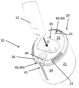
The battery charger 10 generally includes a body 20, a battery-charging slot
30 for receiving and charging the battery 12, one or more power inputs 40 for
supplying
the battery charger 10 with electrical power, and an energy storage 14 for
storing and
conveying electrical power to the battery 12 when connected to the charger 10
The body 20 forms the corpus of the battery charger 10 and provides
structure thereto. The body 20 is typically hollow and houses suitable
internal
components and electrical circuitry which allow it to receive electrical power
from a
separate supply and transfer it to the battery 12. The battery charger 10 is
generally
intended to be placed within a receptacle, such as the cup holder slot of a
vehicle. The
3
CA 02858056 2014-07-30
body 20 is therefore shaped and sized to match the shape and size of the
receptacle
(e.g. cup holder slot). Such a shape is generally, but not exclusively,
cylindrical, as
shown in Figs. 1A and 1B. Irrespective of its shape, the body 20 is defined by
an outer
surface 21, a top surface 22, and a bottom surface 23.
The outer, top, and bottom surfaces 21,22,23 define the contour and shape of
the body 20. In the embodiment shown in Figs. 1A and 1B, the body 20 is a
cylinder
and the outer surface 21 is therefore rounded. It will be appreciated that
since the body
20 can assume other shapes, so too can the outer, top, and bottom surfaces
21,22,23.
The outer surface 21 extends between and connects the top surface 22 and the
bottom
surface 23. The top surface 22 is the surface of the body 20 which is visible
when the
body 20 is placed on its resting surface in the receptacle, while the bottom
surface 23 is
the surface which is hidden when the body 20 is placed on the resting surface.
The outer and bottom surfaces 21,23 of the body 20 are shaped and sized to
be inserted into, and removed from, a receptacle such as a cup holder. Once so
inserted, the receptacle will enclose the bottom surface 23 entirely, and at
least part of
the outer surface 21. As discussed above, the receptacle is generally a cup
holder slot
of a vehicle. Once so inserted, the outer and bottom surfaces 21,23 may form a
friction
fit with the inner surfaces of the receptacle. The expression "friction fit"
refers to the
increased frictional contact between the outer and bottom surfaces 21,23 and
the inner
surfaces of the receptacle when the body is inserted therein, such that
removal of the
body 20 from the receptacle requires the user of the battery charger 10 to
apply a
certain force to the body 20.
The body 20 can be made of any suitable material. For example, if the battery
charger 10 is intended to be placed in the cup holder slot of a vehicle, the
body 20 can
be made of a resilient material such as silicone rubber which allows the body
20 to
deform to match the shape of the cup holder slot to be placed therein, and
which
returns the body 20 to its original shape when removed from the cup holder
slot,
thereby allowing the friction fit. Alternatively, the body 20 can be made of a
more firm
but still resilient material which allows the body to be pressure or friction
fitted into the
cup holder slot. In yet another alternative, the body 20 can be made of a
rigid polymer
and sized and shaped to match the dimensions of standard cup holder slots. It
can thus
4
CA 02858056 2014-07-30
be appreciated that the body 20 can be made of many different materials, the
selection
of which is largely dependent on of the intended use of the battery charger
10.
The battery charger 10 also has one or more battery-charging slots 30 (or
simply "charging slot 30"). Each charging slot 30 receives the battery 12
therein, such
as along the direction indicated by the arrow D in Fig. 1A. The charging slot
30 also
allows electrical power to be transferred to the battery 12. In the embodiment
of Figs.
1A and 1B, the charging slot 30 is a groove or opening which extends into the
body 20
from the top surface 22. It is appreciated that the charging slot 30 may also
extend into
the body 20 from a side surface, such as the outer surface 21, depending on
the
desired accessibility of the charging slot 30 and the intended use of the
battery charger
10, amongst other possible factors. The shape of the charging slot 30 shown in
Fig. 1A
can vary and is primarily dependent on the shape of the battery 12 to be
received
therein (i.e. the charging slot 30 has a profile/shape which corresponds or is
complementary to that of the battery 12). The shape of the inner surfaces of
the
charging slot 30 can therefore match the peripheral surface of the battery 12
to be
inserted therein, thereby helping to secure the battery 12 within the charging
slot 30.
The number of charging slots 30 for a given battery charger 10 can also vary,
and is not
limited to the single charging slot 30 shown in Figs. 1A and 1B. Indeed, the
battery
charger 10 can have more than one charging slot 30, where each charging slot
30 is
configured to receive a corresponding battery 12 therein.
The one or more power inputs 40 of the battery charger 10 receive electrical
power from an external power source and transfer it through the internal
electrical
circuitry of the body 20 and, directly or indirectly, to the battery 12. Each
power input 40
can therefore be any port, socket, or connector. Each one of the power inputs
40 is
located on the top surface 22, the outer surface 21, or both, so that it can
be readily
accessible by the user when the battery charger 10 is placed against the
resting
surface. However, in the depicted embodiment whereby the battery charger 10 is
shaped and configured so as to fit snugly within a circular cup holder
receptacle of a
vehicle, it is advantageous for the power input(s) 40 to be located on the top
surface 22
of the charger 10. Accordingly, when the battery charger 10 is disposed within
the cup
holder receptacle of the vehicle, a power supply wire (e.g. from the vehicles
12V DC
electrical system, for example) can be connected with the power input 40 of
the charger
5
CA 02858056 2014-07-30
(such as to either directly power or "re-charge" the charger 10) without it
needing to
be removed from within the cup holder.
When directly connected to an external power source, via the input(s) 40, the
external power source may be used to directly charge the battery 12 within the
charger
5 10.
However, the battery charger 10 also stores electrical power supplied to it,
in
addition to being able to convey electrical power directly to the battery. The
battery
charger 10 therefore includes an energy storage 14, which is housed within the
body
20. The energy storage 14 is in electrical communication with the battery-
charging slot
30 and with the one or more of the power inputs 40, as shown schematically in
Fig. 1A.
10 This
allows the energy storage 14 to receive electrical power from the one or more
power inputs 40, to store it, and to later transfer it to the battery via the
charging slot 30.
As such, the energy storage 14 can include a capacitor, a battery, or other
similar
electrical energy storage device. Alternatively, the energy storage 14 can be
configured
to allow the electrical power received from the power inputs 40 to bypass the
energy
storage 14 altogether, and be transferred directly to the charging-slot 30 and
ultimately,
to the battery 12 contained therein. It can thus be appreciated that such an
energy
storage 14 allows the battery charger 10 to be portable so that it can be used
to charge
the battery 12 remotely of the supply from which the battery charger 12 itself
received
electrical power.
The number and configuration of the power inputs 40 may vary. In the
embodiment shown in Figs. 1A and 1B, the battery charger 10 has two different
power
inputs 40i,40ii.
The power input 40i has a first power connector 41 located on the top surface
22 of the body 20 which extends into the body 20 from the top surface 22. The
first
power connector 41 can be any socket or port which allows a first input of
electrical
power to the internal circuitry of the body 20. Consider again the example
where the
battery charger 10 is to be secured into a cup holder slot of a vehicle. The
first power
connector 41 allows for part of the vehicle's electrical power supply to be
supplied to the
battery charger 10, via suitable electrical cable. This can be achieved as per
the
following example: a cable joins the first power connector 41 to the outlet of
the
cigarette lighter of a car. This allows the car's 12 V electrical power supply
to provide
electrical power to the power input 40i via the cigarette lighter outlet and
the first power
6
CA 02858056 2014-07-30
connector 41. This electrical power can be supplied at 12 V, or at any other
suitable
voltage. This configuration of the power input 40i can be particularly
suitable where it is
desired to power the battery charger 10 from a vehicle.
The power input 40ii has a second power connector 42. The second power
connector 42 has a locking channel 43 and a connector opening 44. The locking
channel 43 is an elongated groove which extends into the body 20 from the
outer
surface 21, and which extends along a vertical direction beginning at the top
surface 22.
The locking channel 43 receives a corresponding mating part so as to secure
that part
to the body 20. The connector opening 44 is a socket which is connected to the
internal
circuitry of the battery charger 10. In use, the connector opening 44 receives
the
prong(s) or pin(s) of a plug so that electrical power can be transferred into
the battery
charger 10 via the connector opening 44. The second power connector 42 can be
particularly suited to supplying the battery charger 10 with electrical power
from an
external power source, such as mains power via an electrical outlet, as will
be
discussed in further detail below, and where it is desired to transfer
electrical power at
higher standard voltages (e.g. 110 V, 120 V, or 220 V) than can be transferred
via the
first power connector 41. It will be appreciated that the battery charger 10
can be
equipped with one, or both, of the first and second power connectors 41,42.
In some embodiments, the body 20 may have a peripheral friction element 24
which helps to keep the body 20 in position. The peripheral friction element
24 of the
body 20 is located on either the outer surface 21, the bottom surface 23, or
both. The
friction element 24 is thus located on an outside boundary or perimeter of the
body 20,
which allows it to engage with the inner surface of the receptacle against
which the
battery charger 10 is ultimately placed. The friction element 24 increases the
frictional
contact with the inner surface, thereby helping to reduce movement of the
outer or
bottom surfaces 21,23 on which the friction element 24 is located with respect
to the
inner surface. Said differently, the friction element 24 helps to maintain the
body 20,
and thus the battery charger 10, in position within the receptacle. The
friction element
24 can therefore be made of any material which helps it to reduce relative
movement of
the body 20. Some of these materials include, but are not limited to, rubber,
rough
textiles, and other friction-enhancing materials. Similarly, it will be
appreciated that the
7
CA 02858056 2014-07-30
friction element 24 can have numerous configurations in order to achieve such
functionality, some of which are now discussed in greater detail.
The friction element 24 may include a plurality of friction slots 25, each one
of
which extends into the body 20. Each slot 25 is located between the bottom
surface 23
and the outer surface 21, along a peripheral chamfered edge 26. The slots 25,
whether
alone or in a grouping of multiple slots, help the user to grip and retain the
body 20. As
such, and if desired, the slots 25 can also be provided along a chamfered edge
26
between the top surface 22 and the outer surface 21.
The friction element 24 may also include, in addition to the slots 25 or
independently thereof, one or more friction pads 27 located on the bottom
surface 23 of
the body 20. The friction pads 27 can be any textured, ribbed, pointed,
adhesive, or
other friction-enhancing surface which engages the bottom inner surface of the
receptacle so as to reduce or prevent movement of the body 20 with respect to
the
bottom inner surface. The arrangement of the friction pads 27 along the bottom
surface
23 can vary, and is not limited to the three friction pad 27 configuration
shown in Fig.
1B.
Fig. 1C provides an example showing how the battery may be secured into
the battery-charging slot 30. The charging slot 30 may have one or more input
connectors 32 which are located in the body 20 near a base 34 of the charging
slot 30.
The input connectors 32 engage corresponding terminals of the battery to
transfer
electrical power thereto, when the battery is secured in position within the
charging slot
30. The battery can be secured in its charging position within the charging
slot 30 via
one or more securing pegs 33 which project vertically away from the base 34
and/or
into the charging slot 30. The securing pegs 33 engage corresponding openings
in the
bottom of the battery so as to secure the battery within the charging slot 30
such that
movement of the body 20, as caused by a vehicle's movement, will not act to
dislodge
or otherwise eject the battery from the charging slot 30.
It may also be desirable to provide a charge indicator 28 on a visible portion
of the body 20, such as the top surface 22 or outer surface 21, which
indicates the
charging status of the battery or the battery charger 10. The charge indicator
28 can
take many different forms, such as that of a light-emitting diode (LED) which
shows the
8
CA 02858056 2014-07-30
colour red when the battery or battery charger 10 is not fully charged, and
green when
the battery or battery charger 10 is fully charged.
An example of the placement and use of the battery charger 10 will now be
described with reference to Figs. 1A to 1C. The body 20 of the battery charger
10 is
placed within a cup holder slot of a car. The interior of the cup holder slot
is the
receptacle for the purposes of this example. Since cup holder slots generally
have
circular cross-section openings and are adapted to receive cups therein, the
outer
surface 21 of the body 20 accordingly has a generally circular perimeter and
corresponding circular cross-sectional profile. The body 20 is shaped and
sized to be
insertable into the cup-holder slot by snug, pressure or friction fit.
Alternatively, the body
can be more loosely placed within the cup holder slot and its relative
movement
restricted by the one or more friction elements 24 discussed herein.
Irrespective of how
relative movement of the body 20 is reduced or eliminated, the body 20 is
securely
positioned within the cup holder slot such that the motion of the car will not
easily
15 dislodge it.
If the battery charger 10 is not already fully charged, electrical power can
be
supplied to the battery charger 10, and thus the battery 12 when connected
therein,
either via the first power connector 41, the second power connector 42, or
both. This
electrical power is transferred directly to the battery 12, or can be stored
in the energy
20 storage 14 for transferral to the battery 12 at a later time. If
electrical power is
transferred to the energy storage 14, the battery charger 10 can be removed
from the
cup holder slot and transported with a user. When a user wishes to charge a
battery 12,
the user can simply insert the battery 12 into the charged battery-charger 10
via the
charging slot 30, even when the battery charger 10 is not connected to any
other power
supply source.
It can be appreciated that such a battery charger 10 is useful as a portable
charging station, and whenever it is desired to have a portable source of
electrical
power. This is often the case when camping. The battery charger 10 can be used
to
charge a host of different portable camping devices such as a lantern,
flashlight, or
mobile telephone, for example only.
9
CA 02858056 2014-07-30
There is also disclosed, with reference to Fig. 2, a battery charging system
60. In addition to the battery charger 10 disclosed herein, the charging
system 60 has
an AC power adapter 50 which transfers an external supply of electrical power
to the
battery charger 10 for storage therein and/or direct charging of the battery
therein. The
power adapter 50 can be used, for example, where the car's electrical power is
not
available to charge the battery charger 10. In such a situation, the battery
charger 10
can be charged with the power adapter 50, which receives electrical power from
an
outlet source and stores electrical power. It can thus be appreciated that the
charging
system 60 allows the battery charger 10 to remain in place, such as in a cup
holder slot
of a car, because the power adapter 50 can be brought to the battery charger
10 to
provide a charge wherever it is located.
An embodiment of the power adapter 50 is shown in Fig. 3. The power
adapter 50 has an adapter body 57 which makes up the structure of the power
adapter
50 and allows it to be mounted to, and removed from, the battery charger. The
adapter
body 57 is both secured to the battery charger, and forms an electrical
connection with
the battery charger to transfer electrical power thereto. The power adapter 50
has a
mounting bracket 51 which engages the body of the battery charger, and a power
socket 54 to receive electrical power from an external power source.
The mounting bracket 51 both secures the power adapter 50 to the battery
charger, and forms an electrical connection with the battery charger to
transfer electrical
power thereto. The mounting bracket 51 has a locking mechanism 52 which
engages
the body of the battery charger, and a power output 53 which engages a
corresponding
power input of the battery charger to supply electrical power to thereto. It
can thus be
appreciated that many configurations of the mounting bracket 51 are within the
scope of
the present disclosure.
For example, in the embodiment described above where one of the power
inputs of the battery charger has a second power connector with a locking
channel and
a connector opening, the locking mechanism 52 of the mounting bracket 51 can
include
a slide lock 55 which can be inserted into the locking channel and displaced
therein,
thereby preventing the power adapter 50 from disengaging the battery charger.
The
power output 53 of such a mounting bracket 51 can include a prong connector 56
which
can be inserted into, and removed from, the connector opening of the second
power
CA 02858056 2014-07-30
connector to supply electrical power thereto. This supply can be at a higher
voltage
(e.g. 110 V, 120V, or 220 V).
The power socket 54 can be any hollow part into which an electric plug can
be inserted. The power socket 54 allows the power adapter to receive
electrical power
from the external power source, such as a standard 120 V or 220 V electrical
outlet,
thereby charging the power adapter 50 and/or transferring electrical power to
the
battery charger.
The above description is meant to be exemplary only, and one skilled in the
art will recognize that changes may be made to the embodiments described
without
departing from the scope of the invention disclosed. Still other modifications
which fall
within the scope of the present invention will be apparent to those skilled in
the art, in
light of a review of this disclosure, and such modifications are intended to
fall within the
appended claims.
11